ORION TELESCOPES & BINOCULARS SynScan 7960 User manual

Orion SynScan™GPS
#7960
INSTRUCTION MANUAL
IN 515 Rev. A 10/13
Corporate Offices: 89 Hangar Way,
Watsonville CA 95076 - USA
Toll Free USA & Canada: (800) 447-1001
International: +1(831) 763-7000
Copyright © 2020 Orion Telescopes & Binoculars.All Rights Reserved. No part of this product instruction or
any of its contents may be reproduced, copied, modied or adapted,without the prior written consent of Orion
Telescopes & Binoculars.
AN EMPLOYEE-OWNED COMPANY

2
Congratulations on your purchase of
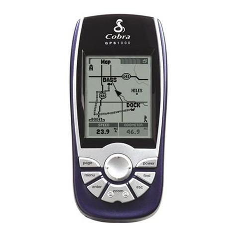
the Orion GPS (OGPS).
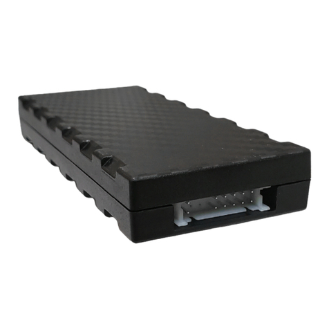
The OGPS is a compact all-in-one
GPS module solution to connect to a
SynScan computer telescope GoTo
system mounts such as Orion Atlas,
Sirius and SkyView Pro mounts.
The OGPS provides accurate geo-
metrical coordinates and serves as a
precise real-time clock for the GoTo
system.
The receiver continuously tracks all
satellites in view and provides accurate satellite positioning data. The OGPS is
optimized for good performance, low cost, and maximum exibility.
Parts List
• Orion SynScan GPS mouse (OGPS) with 1.5m cable
with MINIDIN (F) connector
• 50cm adapter cable with MINIDIN (F) connector and RJ-12,
6 pin connector
• Manual
System Requirements
SynScan Hand Controller rmware Version 3.32 or later is required in order to
connect to the OGPS.
Please see the SynScan Hand Controller manual for rmware update procedure.
Alternatively the link below will take you to the product support page for the
SynScan Hand Controller where the manual, rmware and rmware loader soft-
ware can be downloaded.
http://www.telescope.com/catalog/product.jsp?productId=99365
Setup
1. If the rmware version of your SynScan hand controller is earlier than
version 3.32, you should update the rmware to version 3.32 or later.
2. Please see the SynScan Hand Controller manual for rmware update
procedure.
3. If the rmware version of the SynScan hand controller is version 3.32 or
later, your hand controller is ready to be connected to OGPS.
4. First connect the adapter cable to OGPS (Figure 1).
5. Plug the RJ-12 connector on the end of the adapter cable into the RJ-12
socket of the SynScan hand controller as shown in Figure 2.
Figure 1. Connecting the GPS to the
adapter cable.

3
6. Connect DC power (12V):
a. If the hand controller is
connected to the mount, plug
the 12V DC power source
into the mount and press the
mount’s power switch on.
b. If the hand controller is not
connected to the mount, plug
the 12V DC power source
directly into the hand controller.
For instance when in stand-
alone mode, updating hand
controller rmware without
having to attach hand controller to mount.
7. After you power on the hand controller, you will see “Initializing…” displayed
on the LCD for 2 seconds, then the hand control will nd the GPS receiver
module is connected and after press ENTER, the hand control will prompt to
enter the time zone and daylight saving.
8. After setting time zone and daylight saving, the LCD of the hand control will
display blinking text “GPS Fixing…” The rst time you connect the GPS to
the hand controller; it will take at least 50 seconds to x on the GPS signal.
It may take longer, depending on the weather and environment. If it is the
rst time to use the OGPS or it has been more than a week since last time
connecting the OGPS, the time to x current coordinates will take more than
3 minutes.
9. After the OGPS has xed on the GPS signal, the hand controller will display
the version number if the hand controller is connected to the mount, or
the LCD will display “No link to M.C.” and “Stand-alone mode”, if the hand
controller is not connected to the mount.
10. Press ESC, and the hand controller will function as normal. If the GPS
signal is xed successfully, the hand controller will skip the location, date,
and time entry. The date, time, and location will be automatically updated
from the OGPS.
11. In the SynScan hand controller menu, there is a submenu “GPS” under
Utility menu. In this GPS menu, you can read the GPS information. To reach
this menu, press the UTILITY key, then press the scroll keys until “GPS”
appears on the LCD screen. Press ENTER and the hand control will acquire
GPS information within 2 seconds, assuming the OGPS successfully xes
on the GPS signal.
12. When the OGPS xes, “GPS information:” will display on the rst line of the
LCD. You can press the scroll keys to check the GPS information.
Figure 2. Connecting the GPS to hand
controller.

4
The letters (a) to (l) show the display sequence of the GPS Information when you
press the scroll keys.
a. Shows the latitude of the current site.
b. Shows the longitude of the current site.
c. Shows the current date.
d. Shows the current universal time (UT)
e. Shows the current local time (LT)
f. Shows the time zone, which is retrieved from the user-entered data.
g. Shows the current local sidereal time (LST).
h. Shows the altitude of the current site in meters.
i. Shows the received GPS signal quality.
There are 4 levels of GPS signal quality, which are “No x”, “2D”, “3D” and
“3D+DGPS”. The most accurate signal quality is “3D+DGPS”, “3D” is the
second best signal quality, and “2D” is the lowest useable signal quality.
“No x” means that the GPS is currently attempting to x on a signal, or
cannot acquire the signal.
j. Shows the number of GPS satellites which are in the visible sight of the
OGPS.
k. Shows the number of GPS satellites which are currently xed upon by
the OGPS.
l. Shows the magnetic variation (in degrees) of the current observing site.
To leave the “GPS Information” submenu press ESC. The other functions and
operations of the hand controller are unchanged, and are the same as described
in the SynScan Instruction Manual.

5
Specifications
Receiver Type: 48-Channel, L1 C/A Code
Accuracy: Position 5m CEP
Velocity 0.1m/s
Startup Time: <5 seconds hot start
<35 seconds warm start
<40 seconds cold start
Reacquisition: 1 second
Sensitivity: -146dBm acquisition
-160dBm tracking
Update Rate: 1 Hz
Dynamics: 4G (39.2 m/s2)
Operational Limits: Altitude <18,000m or Velocity <515m/s
Serial Interface: RS-232
Protocol: SynScan Position, Velocity & Time II Binary Message
Input Voltage: 2.7V ~ 6.0V
Current Consumption: <100mW (3.3V)
Operating Temperature: -40°C ~ +60°C
Humidity: 5% ~ 95%

6
Corporate Offices: 89 Hangar Way, Watsonville CA 95076 - USA
Toll Free USA & Canada: (800) 447-1001
International: +1(831) 763-7000
Copyright © 2020 Orion Telescopes & Binoculars.All Rights Reserved. No part of this product instruction or
any of its contents may be reproduced, copied, modied or adapted, without the prior written consent of Orion
Telescopes & Binoculars.
AN EMPLOYEE-OWNED COMPANY
One-Year Limited Warranty
This Orion product is warranted against defects in materials or workmanship for
a period of one year from the date of purchase. This warranty is for the benet of
the original retail purchaser only. During this warranty period Orion Telescopes &
Binoculars will repair or replace, at Orion’s option, any warranted instrument that
proves to be defective, provided it is returned postage paid. Proof of purchase
(such as a copy of the original receipt) is required. This warranty is only valid in the
country of purchase.
This warranty does not apply if, in Orion’s judgment, the instrument has been
abused, mishandled, or modied, nor does it apply to normal wear and tear. This
warranty gives you specic legal rights. It is not intended to remove or restrict your
other legal rights under applicable local consumer law; your state or national statu-
tory consumer rights governing the sale of consumer goods remain fully appli-
cable.
For further warranty information, please visit www.OrionTelescopes.com/warranty.
Table of contents


