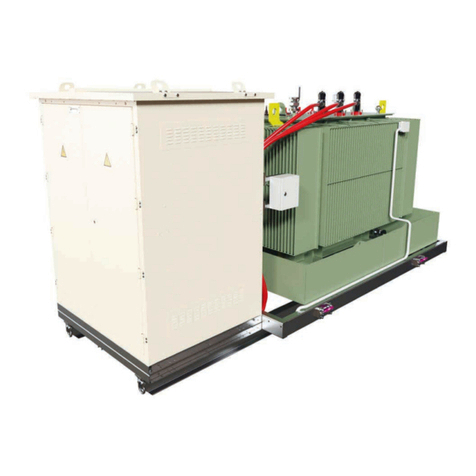
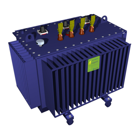
Ormazabal velatia transforma Instruction manual

transforma
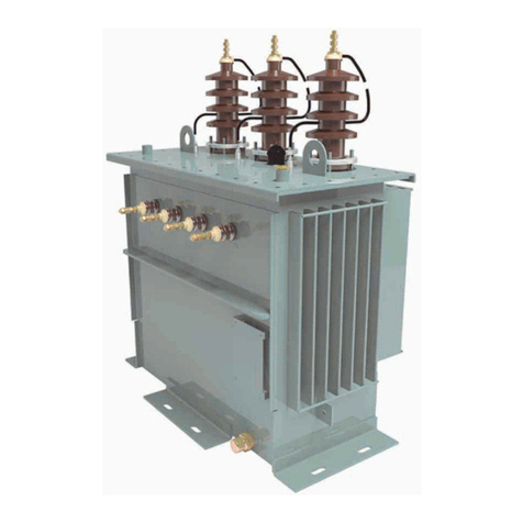
Pad-mounted dielectric
liquid-immersed electrical power
transformers
General instructions
IG-248-EN version 01; 23/10/2015

Legal deposit: BI-800/2015
CAUTION!
When a medium-voltage switchgear unit is operating, certain components are live, other parts may be in movement and some may reach
high temperatures. Therefore, the use of this equipment poses electrical, mechanical and thermal risks.
Inordertoensureanacceptablelevelofprotectionforpeopleandproperty,andincompliancewithapplicableenvironmentalrecommendations,
Ormazabal designs and manufactures its products according to the principle of integrated safety based on the following criteria:
•Elimination of hazards wherever possible.
•Where elimination of hazards is neither technically nor economically feasible, appropriate protection functions are
incorporated in the equipment.
•Communication about remaining risks to facilitate the design of operating procedures which prevent such risks, training for
the personnel in charge of the equipment, and the use of suitable personal protective equipment.
•Use of recyclable materials and establishment of procedures for the disposal of equipment and components so that once
the end of their service lives is reached, they are duly processed in accordance, as far as possible, with the environmental
restrictions established by the competent authorities.
Consequently, the equipment to which the present manual refers complies with the requirements of section 11.2 of the future
IEC standard 62271-1. It must therefore only be operated by appropriately qualified and supervised personnel, in accordance with the
requirements of standard EN-50110-1 on the safety of electrical installations and standard EN-50110-2 on activities in or near electrical
installations. Personnel must be fully familiar with the instructions and warnings contained in this manual and in other recommendations of a
more general nature which are applicable to the situation according to current legislation. State Gazette BOE 269, dated 10 November, and
the update in accordance with R.D. 54/2003).
The above must be carefully observed, as the correct and safe operation of this equipment depends not only on its design but also on general
circumstances which are in general beyond the control and responsibility of the manufacturer. More specifically:
•The equipment must be handled and transported appropriately from the factory to the place of installation.
•All intermediate storage should occur in conditions which do not alter or damage the characteristics of the equipment or its
essential components.
•Service conditions must be compatible with the equipment rating.
•The equipment must be operated strictly in accordance with the instructions given in the manual, and the applicable operating
and safety principles must be clearly understood.
•Maintenance should be performed properly, taking into account the actual service and environmental conditions in the place
of installation.
The manufacturer declines all liability for any significant indirect damages resulting from violation of the guarantee, under any jurisdiction,
including loss of income, stoppages and costs resulting from repair or replacement of parts.
Guarantee
The manufacturer guarantees this product against any defect in materials and operation during the contractual period. In the event that
defects are detected, the manufacturer may opt either to repair or replace the equipment. Improper handling of this equipment and its repair
by the user shall constitute a violation of the guarantee.
Registered Trademarks and Copyrights
All registered trademarks cited in this document are the property of their respective owners. The intellectual property of this manual belongs
to the manufacturer.
In view of the constant evolution in standards and design, the characteristics of the elements contained in this manual are subject to change
without prior notification.
These characteristics, as well as the availability of components, are subject to confirmation by Ormazabal.

General instructions
transforma pad-mounted
IG-248-EN version 01; 23/10/2015
3
Contents
1 Description and main characteristics. . . . . . . . . . . . . . . . . . . . . . . . . . . . . . . . . . . . . . . 4
1.1 Design, manufacturing and testing . . . . . . . . . . . . . . . . . . . . . . . . . . . . . . . . . . . . . . . . . . . . . 4
1.1.1 Individual or routine tests . . . . . . . . . . . . . . . . . . . . . . . . . . . . . . . . . . . . . . . . . . . . . . . 5
1.1.2 Test protocol. . . . . . . . . . . . . . . . . . . . . . . . . . . . . . . . . . . . . . . . . . . . . . . . . . . . . . . . . 5
2 Transport and handling . . . . . . . . . . . . . . . . . . . . . . . . . . . . . . . . . . . . . . . . . . . . . . . . . . 5
2.1 Transport on a forklift truck . . . . . . . . . . . . . . . . . . . . . . . . . . . . . . . . . . . . . . . . . . . . . . . . . . . 6
2.2 Transport using a crane . . . . . . . . . . . . . . . . . . . . . . . . . . . . . . . . . . . . . . . . . . . . . . . . . . . . . . 6
3 Storage . . . . . . . . . . . . . . . . . . . . . . . . . . . . . . . . . . . . . . . . . . . . . . . . . . . . . . . . . . . . . . . 7
4 Installation. . . . . . . . . . . . . . . . . . . . . . . . . . . . . . . . . . . . . . . . . . . . . . . . . . . . . . . . . . . . . 8
4.1 Reception of the transformer . . . . . . . . . . . . . . . . . . . . . . . . . . . . . . . . . . . . . . . . . . . . . . . . . . 8
4.2 Transformer site . . . . . . . . . . . . . . . . . . . . . . . . . . . . . . . . . . . . . . . . . . . . . . . . . . . . . . . . . . . . 8
4.3 Transformer electrical connections . . . . . . . . . . . . . . . . . . . . . . . . . . . . . . . . . . . . . . . . . . . . . 9
5 Implementation. . . . . . . . . . . . . . . . . . . . . . . . . . . . . . . . . . . . . . . . . . . . . . . . . . . . . . . . 10
5.1 Transformer verification before commissioning . . . . . . . . . . . . . . . . . . . . . . . . . . . . . . . . . . . 10
6 Maintenance . . . . . . . . . . . . . . . . . . . . . . . . . . . . . . . . . . . . . . . . . . . . . . . . . . . . . . . . . . 11
6.1 Access for maintenance operations. . . . . . . . . . . . . . . . . . . . . . . . . . . . . . . . . . . . . . . . . . . . 11
6.2 Maintenance frequency . . . . . . . . . . . . . . . . . . . . . . . . . . . . . . . . . . . . . . . . . . . . . . . . . . . . . 12
6.3 Repairs. . . . . . . . . . . . . . . . . . . . . . . . . . . . . . . . . . . . . . . . . . . . . . . . . . . . . . . . . . . . . . . . . . 12
7 Additional information . . . . . . . . . . . . . . . . . . . . . . . . . . . . . . . . . . . . . . . . . . . . . . . . . . 13
7.1 Reliability . . . . . . . . . . . . . . . . . . . . . . . . . . . . . . . . . . . . . . . . . . . . . . . . . . . . . . . . . . . . . . . . 13
7.2 Company Registration Certificate . . . . . . . . . . . . . . . . . . . . . . . . . . . . . . . . . . . . . . . . . . . . . 13
8 Final appendix. . . . . . . . . . . . . . . . . . . . . . . . . . . . . . . . . . . . . . . . . . . . . . . . . . . . . . . . . 14

General instructions
Description and main characteristics
transforma pad-mounted
IG-248-EN version 01; 23/10/2015
4
1 Description and main characteristics
1.1 Design, manufacturing and testing
The transforma manufactured by Ormazabal have
been designed and constructed in accordance with
the mandatory standards and they meet the testing
requirements of the applicable legislation[1] as well as
particular customer specifications.
to Enclosure and dielectric liquid
b Medium voltage and low voltage windings
c Medium voltage terminals
d Low voltage terminals
e Tap changer
f Pressure gauge
g Liquid dielectric thermometer
h Liquid dielectric level indicator
i Ferromagnetic core
j Lifting eyes
k Bracing and dragging eyebolts
Fig.1.1 Main components
More specifically, apart from the mineral oil-immersed
transformers, the transforma transformer range is
characterised by its use of natural biodegradable ester as a
dielectric liquid, with the following general characteristics:
• Excellent dielectric properties, with a high water
saturation point, which allows it to maintain high
breakdown voltage values with a high water content.
[1] Medium Voltage Electro-technical Regulations applicable when the
transformer was manufactured.
•
• High fire resistance: Natural dielectric ester is
classified as a K class liquid (Fire point > 300 ºC)
according to Standard IEC 61100. This classification
offers the possibility of avoiding having to install fixed
fire extinguishing systems, according to many of
the medium voltage electro-technical regulations of
different countries.
• High biodegradability in ground and water due to its
natural composition.
• It is not ecotoxic.
• Recyclable and reusable in other favourable
environmental products at the end of its service life.
• Complies with Standard IEC 62270 “New natural
esters for transformers and similar electrical
equipment”
to bcei j fg h
d
k

Description and main characteristics
General instructions
transforma pad-mounted
IG-248-EN version 01; 23/10/2015
5
1.1.1 Individual or routine tests
The transformers are subjected to routine tests, which
guarantee compliance with the applicable standards:
• Winding resistance measurement.
• Transformation ratio measurement and check up of
vector group.
• Measurement of load losses and short-circuit
impedance.
• Measurement of losses and no-load current.
• Power frequency voltage test.
• Induced voltage test.
1.1.2 Test protocol
All the information regarding the transformer tests is
recorded in the Test Protocol enclosed with the transformer
documentation.

Transport and handling
6General instructions
transforma pad-mounted
IG-248-EN version 01; 23/10/2015
2 Transport and handling
For easier transport, each transformer has anchoring and
hoisting elements at the top for transportation and holes in
the slides at the bottom to prevent damage to the cooling
elements.
The transformers can be transported and handled using a
forklift truck or crane.
Risk of machine breaking. The selection of
the lifting elements must be based on the
transformer total weight, shown on the name
plate.
2.1 Transport on a forklift truck
In this case, the transformer must be properly fitted and
fastened to a pallet adequate to handle its weight and size.
Make sure the cooling elements are protected against
possible damage caused by the forklift support:
Fig.2.1 Transporting ,using a forklift truck, a transforma
2.2 Transport using a crane
The tank is robust enough for lifting the transformer by
means of the lifting eyes at the top part of the sides.
Aspects to consider:
• The slings on the eyes must form a minimum angle of
60º with the transformer’s horizontal.
• The slings must not rub or damage the bushings or
other accessories.
Danger of death by crushing and damage to
the transformer or to the installation.
▪ Use the hooks on the top part of the
sides of the transformer tank for lifting the
transformer with a crane while maintaining a
horizontal position at all times.
▪ Do NOT use the eyebolts on the transformer
cover, where applicable.
▪ Use proper hooks to achieve perfectly
vertical elevation.
▪ The chains must form an angle of no less
than 60º with the horizontal. Fig.2.2 Lifting , using a crane, a transforma

Storage 7
General instructions
transforma pad-mounted
IG-248-EN version 01; 23/10/2015
3 Storage
If commissioning is not immediate, transformers must be
stored following the recommendations below:
• Store the transformer in a clean, dry place on firm,
levelled ground.
• If the transformer is equipped with plug-in terminals
or sockets, make sure the conical protector or cap
provided for keeping the connection terminals clean
and intact is in place.
• If the transformer is equipped with doors on the
connection compartment, these must remain closed
for the maximum protection of terminals, accessories
and other components located inside.
When the transformer includes a vegetable-
origin dielectric liquid, storage at temperatures
below 0 ºC should be avoided due to the
specifi c characteristics of natural esters at
low temperatures. The transformer should
therefore be stored indoors and covered with
appropriate protectors for this purpose.

Installation
8General instructions
transforma pad-mounted
IG-248-EN version 01; 23/10/2015
4 Installation
The manufacturer is not responsible for
transformer installation. This has to be
carried out in accordance with the applicable
legislation.
4.1 Reception of the transformer
The transformer is supplied prepared for its connection to
medium voltage and low voltage lines. Some parts may be
supplied dismantled for transport.
When the transformer is received (at the customer
warehouse or at the transformer’s final location), it must
be carefully inspected, paying special attention to the
following aspects:
• The characteristics of the transformer, as indicated
on the Name Plate, must coincide with those in the
Test Protocol; and these must correspond with those
specified on the corresponding order.
• Verify the general condition of the transformer and
check for absence of dents, especially on the cooling
equipment and on the medium voltage and low
voltage bushing insulators.
In case any accessory is missing or
damaged, immediately notify the carrier and
Ormazabal.
• Verify that the transformer has all of its accessories,
ensuring they are not damaged.
• Where the transformer includes seals, these must be
unbroken and untouched.
Fig. 4.1 Purging and sample collector device.
Any manipulation or breakage of a seal
cancels the transformer guarantee as well
as Ormazabal's liability.
If any anomaly is detected upon the reception
of the transformer, immediately notify
Ormazabal. If after a 15 day period, we have
not received a report of anomalies or defects
found, it is assumed the transformer arrived
in perfect conditions and Ormazabal will not
be responsible for any future anomalies or
their consequences.
4.2 Transformer site
When the transformer has vegetable-origin dielectric
liquid, the natural esters have higher freezing points than
those of mineral oil. Therefore, the liquid could freeze
during prolonged exposure to temperatures below 0 ºC.
In these cases, the transformer can be powered without
affecting its physical - chemical properties. However, the
transformer should be protected from low temperatures
during prolonged storage periods at low temperatures.
The transformer site for both outdoor and interior
installations, must allow for adequate cooling.
Poor ventilation of the transformer may
cause it to overheat.
Both the technical conditions and the personal and
property safety requirements of the transformer's design
and site are defined in the applicable legislation and
standards.
A horizontal base that supports the transformer must
be prepared, bearing in mind the total weight of the
transformer, which is indicated on its name plate.

Installation 9
General instructions
transforma pad-mounted
IG-248-EN version 01; 23/10/2015
4.3 Transformer electrical connections
Risk of death by electric shock and of
irreversible damage to the transformer or to
the electrical installation.
The transformer electrical connections can
only be performed by qualifi ed personnel
while always observing the proper electrical
safety measures.
Connect the transformer as follows:
1. Verify that the electric power supply to the transformer
meets the service values indicated in the transformer’s
name plate.
Risk of causing irreversible damage to the
transformer or to the electrical installation.
▪ Verify that the electric power supply to
the transformer meets the service values
indicated in the transformer’s name plate.
2. Open all the electrical power sources and interlock or
block the necessary switching devices to prevent the
power supply.
3. Verify that electrical voltage is not present.
4. Earth and short-circuit all the electrical power sources.
5. Delimit and mark the work area properly.
6. Check the correct level of dielectric liquid and the
internal pressure of the transformer.
In case of oil leakages contact the
manufacturer.
7. Earth the transformer tank using round connecting
points for a standard cross-section earthing cable, as
well as an M12 screw (M10 on demand) and 2, 14
mm washers (12 mm for M10). Apply 40-60 Nm of
torque to the M12 (25 - 35 Nm for M10).
Tools:
Standard cross-section earthing cable.
Round connecting points of proper diameter.
1 M12 (M10) screw.
2, 14 mm (12 mm for M10) washers (one for
each side of the connecting points).
Fig. 4.2 Transformer earth connection
Start the electrical connection by earthing
the transformer tank.
8. Connect the transformer to the medium voltage
circuit or primary (if the transformer has a primary
and secondary with a voltage over 1000ºV). Use
flexible connections that do not place any strain on
the transformer bushings. Their size must be enough
to prevent excessive overheating and, at the same
time, allow for the dilatations caused by heat without
damaging the transformer.
The torques must be performed guaran-
teeing the proper electrical contact of the
connections.
9. Connect the transformer to the low voltage circuit
or secondary (if the transformer has a primary and
secondary with a voltage over 1000ºV). Use flexible
connections that do not place any strain on the
transformer bushings. Their size must be enough
to prevent excessive overheating and, at the same
time, allow for the dilatations caused by heat without
damaging the transformer.
The torques must be performed guaran-
teeing the proper electrical contact of the
connections.
10. Connect the transformer’s neutral to the electrical
installation’s neutral.
11. Check that the tap changer position is correct; and
in the case of a multi-voltage transformer, ensure the
medium voltage winding or primary (if the transformer
has a primary and secondary of over 1000ºV) is
connected to the electrical voltage that is going to be
used as service voltage.

Implementation
10 General instructions
transforma pad-mounted
IG-248-EN version 01; 23/10/2015
5 Implementation
5.1 Transformer verification before commissioning
Once the transformer is connected to the medium voltage
and low voltage networks, and before connecting the
electrical power source, the following checks should be
performed:
1. Check that the Medium Voltage network values and
the transformer rated voltage coincide.
The natural esters have higher freezing
points than those of mineral oil. Therefore,
the liquid could freeze during prolonged
exposure to temperatures below 0 ºC.
In these cases, the transformer can be
powered although these situations should
be avoided wherever possible.
2. Where the machine has these instruments, check
the correct oil level on the oil level indicator and a
correct internal pressure on the value indicated by the
compound gauge.
3. Feed the no-load transformer and check its correct
connection and regulation by measuring the values
at the low voltage side. Where the transformer has
natural ester-type dielectric liquid and is powered
after a prolonged period of exposure to temperatures
below 0 ºC, the dielectric fluid might be solid. Once
the load transformer has been powered, it will recover
its usual liquid stage.
4. Regulate the transformer's voltage using the
corresponding tap changer. Take into account the
following safety precautions:
Failure to follow these safety precautions
may result in death by electric shock or
irreversible damage to the transformer or to
the electrical installation.
Were the transformer has a natural ester as
dielectric liquid and has been exposed for a
prolonged period to ambient temperatures
below 0 ºC before being powered, the
fl uid might be solid. The tap change
control CANNOT be used under these
circumstances. The transformer must be
warmed up until the fl uid is liquid enough for
the tap change control to be handled.
4.1 The tap changer shall always be operated without
electrical power. Ensure the handle is well locked
and in its working position.
4.2 Check that the electrical voltage applied
corresponds with the transformer's rated voltage.
In case of anomaly, contact the manufacturer.
4.3 If after commissioning the transformer, it is
necessary to perform an adjustment, follow the
safety instructions specified in section 6.1, Access
for Maintenance Operations, of this document.
Fig.5.1 Tap changer and primary connections
5. Progressively apply the load until the operating power
is achieved, while ensuring that the transformer
temperature does not go over 105 ºC.
Risk of death caused by electric shock and
of irreversible damage to the transformer or
to the electrical installation.
▪ Before handling the installation, exactly
follow the instructions of section 6.1 of this
document.
▪ Do not operate the tap changer with
electrical power applied to the transformer.
Maintenance 11
General instructions
transforma pad-mounted
IG-248-EN version 01; 23/10/2015
6 Maintenance
6.1 Access for maintenance operations
Before performing any maintenance operation on
the transformer, follow the measures required by the
applicable legislation, including:
1. Disconnect all the electrical power sources for the
medium voltage and low voltage circuits until the
transformer is turned off. Interlock or block the
necessary switching devices to prevent the power
supply.
2. Verify that electrical voltage is not present.
3. Earth and short-circuit all the electrical power sources.
4. Using an insulating stick, earth the transformer
bushings and ensure that any static electricity is
discharged.
5. Delimit and mark the work area properly.
6. Check that the transformer does not leak dielectric
liquid.
In case of dielectric liquid leakages, contact
Ormazabal
Fig. 6.1 Filling, purging and sample collector devices for the
switch and primary connections
Fig. 6.2 Secondary compartment with level, temperature and
pressure indicators and secondary connectors

Maintenance
12 General instructions
transforma pad-mounted
IG-248-EN version 01; 23/10/2015
6.2 Maintenance frequency
It is recommended that the transformer undergoes a
regular annual inspection of the following aspects:
1. Water-tightness: check that the transformer does not
leak dielectric liquid.
2. If the machine is fitted with oil level and/or internal
pressure indication instruments, check that the levels
or values measured are appropriate.
3. Cleanliness: check for proper cleanliness and care of
the transformer.
4. Noise: check that the transformer does not produce
strange or untimely noises.
The requirements set out in the applicable
legislation on transformer stations and
substations to protect people and property
which may be damaged by the installations
must also be met.
6.3 Repairs
If the transformer presents any anomaly in its operation,
the user must notify the manufacturer, who must provide
the appropriate instructions.
• If after the transformer inspection, repairs or
modifications are required, these operations must be
performed by the manufacturer.
• If a company other than the original manufacturer
performs the repair or modification, they must place
a plate on the transformer indicating the modification
or repair performed and the new characteristics of the
transformer.

If someone other than Ormazabal handles
and unseals the transformer, it will no longer
be responsible for its operation and reliability.

Additional information 13
General instructions
transforma pad-mounted
IG-248-EN version 01; 23/10/2015
7 Additional information
7.1 Reliability
As shown by the tests, the transformer leaves the factory
free of defects and is ready to provide service for its entire
service life.
In order to maintain that level of reliability, transformers
must be properly handled, stored, transported and
commissioned, applying the corresponding checks
and the protections established in the medium voltage
electro-technical regulations. In addition, the maintenance
instructions listed in this document must be observed.
Additionally, it is required that during its installation, the
necessary precautions are taken to protect personnel who
normally or circumstantially work around it and that those
persons not required for its operation are kept at a safe
distance away from the transformer.
7.2 Company Registration Certificate
The Company registration certificate No. ER - 0227
/ 1996, granted by AENOR-EQ-NET and dated 23 / 5 /
1996, guarantees that our Quality Assurance System
establishes the management criteria, as well as the
procedures and processes that assure delivery of
transformers that are free from defects. This system, which
includes the suppliers, is applied from the product design
and development phase to the After - Sales Service. The
knowledge and learning derived from research and testing
(whether standard or special) are employed to guarantee
uniformity in product component design, manufacturing
and testing procedures, personnel training and continuous
improvement of the entire process.

Final appendix
14 General instructions
transforma pad-mounted
IG-248-EN version 01; 23/10/2015
8 Final appendix
Torque recommended for medium voltage and low voltage
connections:
Recommended tightening torque [Nm]
Metric size M10 M12 M16 M20 M30
Wrench size 17 19 24 30 46
Low voltage
Connection between nuts. 15-20 70-100 250-350
Fastening the palms to the bolt (stainless
steel screws). 25-35 40-60
Screws to the surface of the palms. 25-35 40-70 100-150
Connections at low voltage busbars (steel
bolt and nut). 45-60 65-85 95-130
Medium
voltage
Fastening the terminals to the medium
voltage bolt (brass bolt and screws) 10-15
Screws to the surface of the palms or spades 25-35 40-70 100-150


Subject to change without
prior notification.
For further information,
contact Ormazabal.
Ormazabal
Cotradis
Transformadores, S.L.U.
LOECHES
Spain
www.ormazabal.com
Table of contents
Other Ormazabal Transformer manuals

Ormazabal
Ormazabal velatia transforma.earth Instruction manual

Ormazabal
Ormazabal velatia mb.m Series Instruction manual

Ormazabal
Ormazabal velatia transforma.dis Instruction manual

Ormazabal
Ormazabal CTC Instruction manual

Ormazabal
Ormazabal transforma.hvd Instruction manual

Ormazabal
Ormazabal transforma.bst-pm Instruction manual

Ormazabal
Ormazabal velatia transforma.organic Instruction manual