ORTECO IIa Series User manual

UN21-0145EI
SMART 600J - 800J
ORTECO S.r.l.
Via 2 Giugno, 19
40011 Anzola Emilia (Bo) - Italia
Tel. +39 051 731051
Fax +39 051 731925
mail: orteco@orteco.com
www.orteco.com
SELF-PROPELLED
TRACKED PILE-DRIVER
USE AND
MAINTENANCE MANUAL
Manual code: 130701
Language: english
Edition: 07/2013
IIaSeries
Original instructions in English language
Serial number:


SUMMARY
1 GENERAL INFORMATION..........................................................................................................................1
2 TECHNICAL INFORMATION .....................................................................................................................5
3 SAFETY INFORMATION .......................................................................................................................... 15
4 HANDLING AND TRANSPORTATION ................................................................................................. 17
5 ADJUSTMENT INFORMATION.............................................................................................................. 22
6 INFORMATION FOR USE ........................................................................................................................ 27
7 MAINTENANCE INFORMATION ........................................................................................................... 55
8 BREAKDOWN INFORMATION............................................................................................................... 63
9 INFORMATION FOR REPLACEMENTS ................................................................................................ 64
A ENCLOSURES............................................................................................................................................. 69
ANALYTICAL INDEX
A
Accessories ....................................................................................................................................................... 13
Adjusting of“PROXIMITY device”that stops the hammer’s down stroke .................................. 23
Adjusting the“laser device”that stops the hammer’s down stroke............................................. 25
Adjusting track tension................................................................................................................................ 22
Advice for handling and transportation ................................................................................................ 17
Aim of the manual ............................................................................................................................................1
Analytical index.................................................................................................................................................III
Annexed documentation ...............................................................................................................................3
C
Checking and cleaning the supplementary air filter......................................................................... 57
Cleaning and lubrication of hammer lifting chain............................................................................. 61
Controls to run the machine ...................................................................................................................... 29
D
Dashboard controls (base version) .......................................................................................................... 28
Declaration of conformity........................................................................................................................... 12
Description of the controls......................................................................................................................... 27
Disclaimer notice...............................................................................................................................................3
E
Emergency stop.............................................................................................................................................. 53
Engine identification........................................................................................................................................3
Environmental operating limits ................................................................................................................ 11
F
Fitting the pile driver..................................................................................................................................... 21
G
Gas emissions .................................................................................................................................................. 11
General description..........................................................................................................................................5
Glossary of terms...............................................................................................................................................4
H
Hose check........................................................................................................................................................ 59
Hydraulic oil level check .............................................................................................................................. 60
I
Information and safety signs.........................................................................................................................8
Intended uses .....................................................................................................................................................6

L
Lifting the machine ....................................................................................................................................... 18
Lifting the pile driver..................................................................................................................................... 19
Lifting the truck............................................................................................................................................... 18
Long out-of-use periods.............................................................................................................................. 52
Lubricant comparison table ....................................................................................................................... 62
Lubrication diagram...................................................................................................................................... 56
M
Machine cleaning........................................................................................................................................... 61
Main parts ............................................................................................................................................................5
Maintenance register..................................................................................................................................101
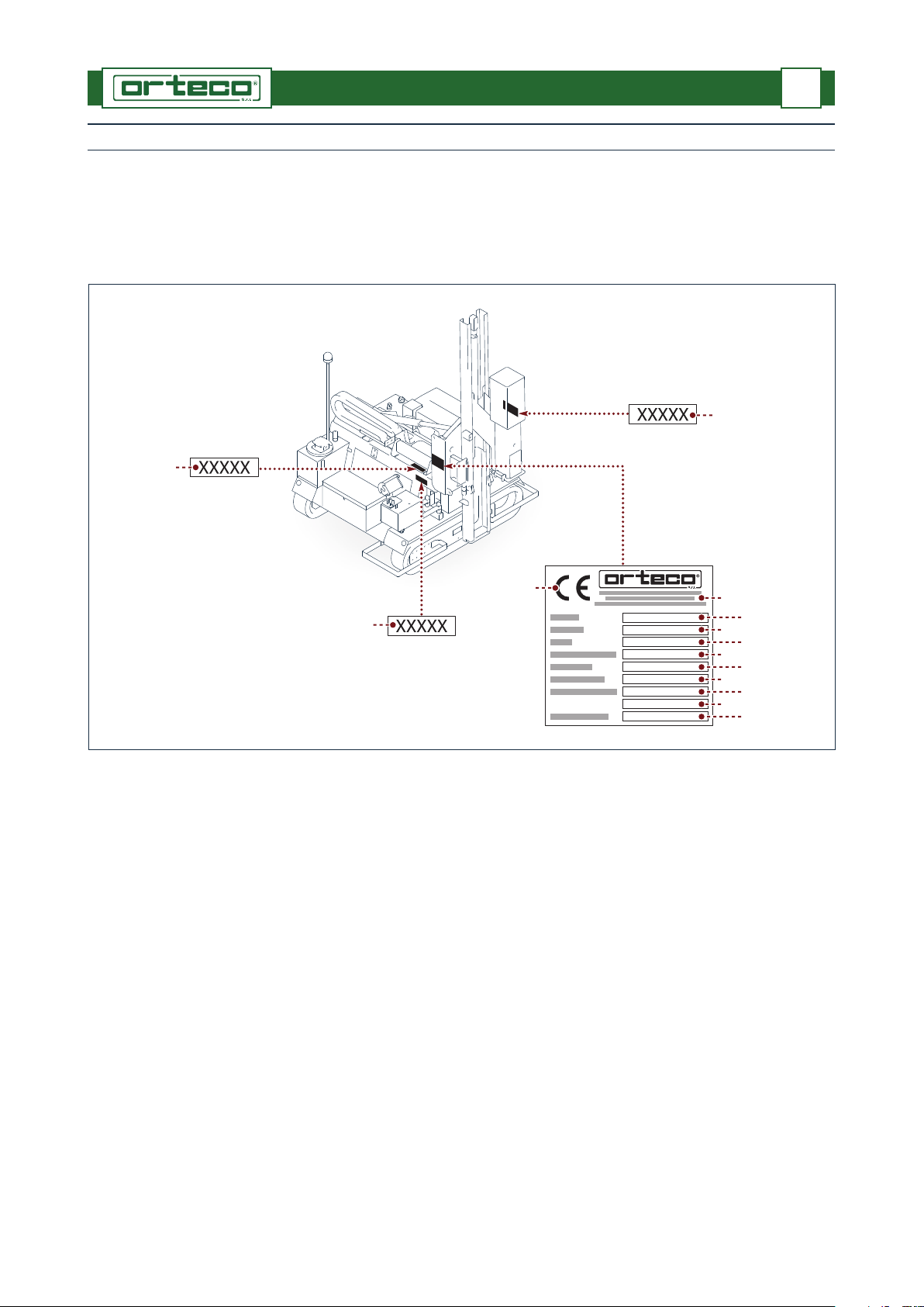
Manufacturer and machine identification details.................................................................................2
Metal pile extraction procedure ............................................................................................................... 38
N
Night-time work or poor visibility conditions...................................................................................... 54
Nut and bolt check ........................................................................................................................................ 57
Nuts and bolts tightening torques chart............................................................................................... 62
O
Operational stop............................................................................................................................................. 53
Operation controls......................................................................................................................................... 30
Operator training...............................................................................................................................................6
Overall dimensions........................................................................................................................................ 10
P
Pile driving procedure .................................................................................................................................. 36
Procedure for getting on and off the transport means.................................................................... 19
Procedure to make holes using the boring device ............................................................................ 42
Procedure to make holes using the corer.............................................................................................. 40
Procedure to make holes using the drill ................................................................................................ 47
R
Radio control.................................................................................................................................................... 69
Re-commissioning......................................................................................................................................... 52
Refuelling .......................................................................................................................................................... 52
Replacing hosing............................................................................................................................................ 66
Replacing supplementary air filter cartridges ..................................................................................... 65
Replacing the chain....................................................................................................................................... 67
Replacing the delivery line filter cartridge (high pressure)............................................................. 65
Replacing the discharge filter cartridge (low pressure) ................................................................... 64
Replacing the stroke plate .......................................................................................................................... 67
Replacing the track reduction gear oil ................................................................................................... 66
Residual risks.......................................................................................................................................................6
S
Safety advice concerning use.................................................................................................................... 27
Safety advice for maintenance.................................................................................................................. 55
Safety advice for the adjustments............................................................................................................ 22
Safety advice in case of faults .................................................................................................................... 63
Safety advice in case of replacements.................................................................................................... 64
Safety devices.....................................................................................................................................................7
Safety instructions for handling and transportation......................................................................... 16
Scrapping the machine................................................................................................................................ 68
Shifting on slopes procedure..................................................................................................................... 35
Shifting procedure......................................................................................................................................... 34
Sound emissions............................................................................................................................................. 10
Starting the engine........................................................................................................................................ 32
Starting the engine with the auxiliary battery .................................................................................... 33

Summary .............................................................................................................................................................III
Supplements.................................................................................................................................................... 14
T
Technical assistance procedure....................................................................................................................3
Technical characteristics.................................................................................................................................9
Track gearmotor oil level check ................................................................................................................ 59
Track tension check ....................................................................................................................................... 60
Transportation procedure........................................................................................................................... 17
U
Use in cold environmental conditions.................................................................................................... 31
Using the verticality system ....................................................................................................................... 50


1
English language Use and maintenance
GENERAL INFORMATION 1
Aim of the manual
This manual, which is an integral part of the machine, has been prepared by the manufac-
turer to provide the operator with the necessary information and criteria for the use and
maintenance of the machine.
The original instructions are supplied by the manufacturer in English language. To fulfil le-
gal or commercial requirements, the original instructions may be supplied by the manufac-
turer in other languages.
Certain illustrations in the manual show the machine with the safety devices and/or guards
removed only in order to make it easier to understand the operations to be performed. The
machine must never be used without the safety devices or guards fitted.
The pictures may differ from the actual machine configuration, but this does not affect the
instructions.
The manufacturer reserves the right to make changes to the manual without prior notice,
with the exception of changes concerning the level of safety.
The manual must be kept, for future reference, until the machine is scrapped.
If the machine is sold, the seller is required to pass on the manual to the new owner.
In the case of discordant information between the machine manual and the attached man-
uals, the machine manual must be considered valid.
The symbols shown in this manual are designed to highlight the operations involving a
certain level of risk in safety terms or important information.
Danger - Warning
This indicates information or procedures which must be followed. Failure to comply
may create a serious risk to the health and safety of people.
Caution - Care
This indicates information or procedures which must be followed otherwise failure
to do so may create a risk to the health and safety of people or cause economic dam-
age.
Information
This highlights useful and important information and procedures.

UN21-0146EI
X
Y
A
N
B
C
D
E
F
G
H
L
M
Z
2
English language Use and maintenance
GENERAL INFORMATION 1
Manufacturer and machine identification details
Identification plate
The picture shows the identification plate and the position of the serial numbers of the
units that make up the machine.
The plate contains all the information to identify the machine and the manufacturer.
Identification plate
A) Manufacturer’s details
B) Machine model
C) Type of machine
D) Serial number
E) Year of manufacture
F) Maximum pressure
G) Required oil flow
H) Engine power
L) Electric voltage
M) Overall weight
N) “CE” marking
Punching
The following serial numbers are punched on the machine.
X) Hydraulic hammer serial number
Y) Pile driver serial number
Z) Tracked truck serial number

3
English language Use and maintenance
GENERAL INFORMATION 1
Engine identification
Engine identification data is shown on the identification plate applied to the engine.
For the meaning of the data contained on the plate see the engine manufacturer’s use and
maintenance manual.
Technical assistance procedure
For technical assistance (machine malfunction, failure, etc.) contact the nearest technical
assistance service or the manufacturer.
When requesting technical assistance, the data shown on the machine’s identification plate,
the work hours shown on the hour meter and the type of failure must be reported.
For motor technical assistance (engine malfunction, failure, etc.) contact the nearest techni-
cal assistance service of the engine manufacturer (see enclosed manual).
Disclaimer notice
The manufacturer cannot be held responsible for the following:
- use of the machine by untrained and/or unauthorised personnel;
- improper use of the machine;
- failure to carry out maintenance;
- unauthorised modifications or repairs;
- use of non-original spare parts or parts not designed specifically for the model con-
cerned.
Annexed documentation
The following documentation is supplied to the Customer together with the use and main-
tenance manual.
- “CE”declaration of conformity of the machine
- engine maintenance booklet
- use and maintenance manual of the boring device
- use and maintenance manual of the corer
- use and maintenance manual of the pile extraction clamp
- use and maintenance manual of the drill
- “hydraulic oil safety and environment data sheet”
- “engine oil safety and environment data sheet”
- “fuel safety and environment data sheet”
- “gear lubricant safety and environment data sheet”
The “Use and maintenance” manuals of the boring device, corer, pile extraction clamp and
drill are supplied only if said parts are installed on the machine.

4
English language Use and maintenance
GENERAL INFORMATION 1
Glossary of terms
Accessory: unit that increases the machine’s functionality for specific operations.
The accessory must be requested by the customer when placing the order.
Supplement: component or unit that completes the machine, which is not included in the
standard model.
The supplement must requested by the customer when placing the order.

UN21-0147EI
G
F
L
M D
E
H
C
B
A
5
English language Use and maintenance
TECHNICAL INFORMATION 2
General description
This machine has been designed and built to sink into the ground steel piles or wood piles
using a percussion hammer.
The machine is made up of a tracked truck for manoeuvres and a percussion hammer to
drive the pile into the ground.
The machine is manufactured in various versions where the main difference is the percus-
sion power of the hammer; the machine is driven by hydraulic power generated by an en-
gine and a pump.
Other accessories can be installed on the machine to drill holes in conglomerates, in the
ground and in rocky ground.
One operator is sufficient to operate the machine; said operator must have the necessary
requisites to use the machine in total safety.
Main parts
A) Pile driver base: it contains the slide for the transversal movement of the column.
B) Column: to position the hammer in the right position to drive the element into the
ground.
C) Percussion hammer: to sink the element into the ground.
D) Heat exchanger: to dissipate the excessive heat of the hydraulic oil.
E) Engine: to supply power to all main parts.
F) Fuel tank: to supply the engine.
G) Hydraulic oil tank: to supply the machine operations (shifting, lifting of hammer, etc.).
H) Track gearmotor: to move the left track.
L) Track gearmotor: to move the right track.
M) Tool box.

6
English language Use and maintenance
TECHNICAL INFORMATION 2
Intended uses
This machine has been designed and built to sink metal piles for guard-rails, wood piles and
metal piles for photovoltaic systems.
Using special accessories approved by the manufacturer, it is possible to extract piles, make
holes and drill (see “Accessories”).
Any other use is considered improper and is therefore forbidden.
Unauthorised uses
The machine must be used in conformity with its technical characteristics; it is forbidden to
make modifications or use the machine for improper uses.
Use of the machine is prohibited in potentially explosive atmospheres.
Use of the machine with equipment not approved by the manufacturer is prohibited.
Use of the machine to transport people is prohibited.
Use of the machine to lift people with the percussion hammer is prohibited.
Use of the machine to drive or extract piles, make holes on manufactured goods or drill the
ground is prohibited when the column is not perfectly vertical.
The machine cannot be driven on the roads as it is not approved for road use.
The installed pile extraction clamp, corer and drill must not be used to drive piles.
Operator training
The operator has the task of carrying out all the operations related to the use of the ma-
chine and ordinary maintenance operations in total safety.
Personnel authorised by the manufacturer must train the operator to transfer the knowl-
edge necessary to carry out the activity independently and without risks.
Residual risks
Danger - Warning
Even if the safety regulations and information contained in this manual are respected
there are residual risks during the use of the machine; the main ones are described
below.
- Risk of crushing of lower limbs in tracks.
- Risk of crushing of upper limbs between the stroke plate and the pile to be driven.
- Thermal danger in case of contact with hot parts.
- Fuel leaking from the tank during machine use or during refuelling may lead to a
fire risk.
- Risk of high-pressure spurts of fluid. A pipe or hose breaking or high-pressure oil leak-
age may lead to injuries and skin infections.
- Risk of being run over. Due to the insufficient visibility when the machine is reversed in
tight spaces with poor lighting there is the risk that objects, animals and people may be
run over.
- Risk of impact. The accidental and sudden lowering of the percussion hammer may seri-
ously injure the operator.

UN21-0148EI
F
B
G
H
A
D
D
C
E
12
7
English language Use and maintenance
TECHNICAL INFORMATION 2
Safety devices
Danger - Warning
On no account must you tamper with or by-pass the safety devices.
Keep all safety devices in good working order through regular maintenance.
The illustration shows the position of the safety devices on the machine.
A) Emergency stop button: to stop the machine in the case of impending risk.
B) Lock valves: these are used to block the movement (extension / retraction) of the jack
in case of rupture of a pipe or drop in pressure. These valves are installed on the jacks (1)
and (2).
C) Maximum pressure valve: this limits maximum operating pressure to prevent over-
loading of the hydraulic system.
The valve installed on each hydraulic distributor is set and sealed by the manufacturer
during testing and must not be altered.
D) Safety guards: these protect the operator from accidental contact with moving tracks.
E) Rotating light: this signals the start up of the machine and is automatically activated in
the ignition phase.
F) Safety lock pin: this protects the operator from the accidental and sudden lowering of
the percussion hammer.
G) Rotating light (optional): signals the machine’s reverse shift motion.
H) Buzzer (optional): signals with an intermittent sound the machine’s reverse shift mo-
tion.

UN21-0149EI
4
6
15
7
7
9
5
3
10
22 HP
LP
23
16
17
9
8
1
20
7
9
8
8
9
2
9
9
2
8
1
14
21
14
3
54
6
15
12
19
11
18
7
9
8
English language Use and maintenance
TECHNICAL INFORMATION 2
Information and safety signs
Danger - Warning
Always respect the safety instructions on the plates.
Check that the plates are always in place and legible; if they are not, replace them
with new ones, maintaining the original location on the machine.
The illustrations show the position of the safety and information signs on the machine. The
meaning of each sign is described below.
1) Risk of crushing of lower limbs in tracks.
2) Risk of limbs being crushed by the machine’s moving parts.
3) Ear defenders must be worn to protect the user’s hearing from loud noises.
4) Safety helmets must be worn.
5) Personal protection equipment requirement: this sign shows the operator is required
to wear gloves.

9
English language Use and maintenance
TECHNICAL INFORMATION 2
6) Carefully read the instruction manual before operating the machine.
7) Attachment points of lifting hooks.
8) Operators and site assistants must keep a safe distance from the machine.
9) Greasing points.
10) Type of oil used for the hydraulic system.
11) Type of engine fuel.
12) Before starting the engine check that the emergency button is not pressed down.
14) This shows the operating noise level emitted by the machine.
15) General hazard.
16) This shows the direction of movement and the relevant manoeuvres of the shifting
control levers.
17) This shows the direction of movement of the accelerator lever to increase or decrease
the number of revolutions of the engine.
18) This specifies the type of engine oil used.
19) This shows the fuel supply open / close turn valve.
20) This shows the battery cut-off device.
21) This shows the direction of movement and the relevant manoeuvres of the pile driver
control levers.
22) This shows the connection of the high pressure delivery hose.
23) This shows the connection of the low pressure draining hose.
Technical characteristics
(**)For the technical characteristics of the engine see the engine manual enclosed.
Percussion hammer model SMART 600J SMART 800J
Engine (**) (**)
Percussion hammer power joule 590 830
Strikes per minute n° min 650 ÷ 1000 680 ÷ 720
Working pressure Mpa 15
Required oil flow l/min 75
Hydraulic oil tank capacity l 110
Fuel tank capacity l 50
Electrical system voltage V dc 12
Maximum longitudinal slope degrees 8
Maximum transversal slope degrees 8
Maximum wading depth mm 430
Maximum speed Km/h 2,1
Maximum towable load kg 1000
Stroke plate weight kg 25
Crawler weight (without accessories) kg 1750
Pile-driver weight (without accessories) kg 1100 1250
Overall weight of machine (tracked truck and pile driver)
(without accessories) kg 2850 3000

UN21-0190EI
N
A
Q
G (*)
H(*)
F(*)
D
C
E
L1L2
M
P
P
B
10
English language Use and maintenance
TECHNICAL INFORMATION 2
Overall dimensions
The illustration shows the general dimensions of the machine when operating and when
resting.
(*) Dimensions of the machine without accessories or supplements.
The dimension (G) corresponds to the maximum length of the pile to be driven into the
ground.
Sound emissions
The sound level, measured in operating condition when driving metal piles, is shown in the
table.
The measurement has been carried out in compliance with the UNI EN 11201:2009 -
UNI EN 996:2009 standards using a Delta Ohm phonometer model HD2010UC.
Model A B C D E F * G * H * L1L2M N P Q
(mm) (°)
SMART 600J
2264 3355 1905 2570 3570 310 2870
4075
125 75
2650
2148 8 10
SMART 800J 4205 2670
SMART 600J SMART 800J
Guaranteed sound power level (LwAG)dBA 112,3 108,9
Guaranteed A-weighted sound pressure level (LpAG) dBA 102,1 100,0
Guaranteed instantaneous C-weighted peak sound pressure level
(LpCpeakG)dBA 135,1 134,2

11
English language Use and maintenance
TECHNICAL INFORMATION 2
The operator and nearby people must wear personal protective equipment (ear de-
fenders, ear plugs, etc.) to reduce the noise level received or eventually work shifts
that foresee interruptions must be programmed to reduce the exposure to noise.
Gas emissions
During operation and/or when standing still, the machine emits the toxic gases listed be-
low.
- Carbon monoxide generated by the exhaust of the engine.
- Hydrogen generated by the engine ignition battery.
- Inflammable and explosive fumes produced by the engine fuel.
Environmental operating limits
The machine works correctly at a temperature between - 20 and + 40 °C, with 80% maxi-
mum relative humidity.

12
English language Use and maintenance
TECHNICAL INFORMATION 2
Declaration of conformity
The picture shows a copy of the “EC” declaration of conformity; the original is issued by the
manufacturer together with this manual.
UN21-0326DL_GB
ORTECO S.r.l.
Via 2 Giugno, 19 – 40011 – Anzola dell’Emilia (BO)
Tel. +39 051731051 - Fax +39 051731925
In the person of Sergio Tassinari as CEO
DECLARES
under own responsability, that the machine :
DESCRIPTION
FUNCTION
M
ODEL
/
C
OMMERCIAL NAME
TYPE /COMMERCIAL NAME
S
ERIAL NUMBER
CODE
Complies to all the relevant dispositions of the Directives of the European Parliament and
Council:
- “Machine” 2006/42/CE published in G.U.U.E. on 09.06.2006.
- “EMC” 2004/108/CE published in G.U.U.E. on 31.12.2004.
- “Noise” 2000/14/CE published in G.U.U.E. on 03.07.2000 – 2005/88/CE published in
G.U.U.E. on 27.12.2005.
Also declares that the machine has been projected and produced in compliance with the
harmonized standard:
•EN ISO 12100-1 (2009) Machinery Safety – basic concepts, design general principles – Part 1: Basic
therminology, methodology.
•EN ISO 12100-2 (2009) Machinery Safety – basic concepts, design general principles – Part 2: Technical
principles.
•EN ISO 14121-1 (2007) Machinery Safety – risk evaluation - Part 1: Principles.
•EN 996 (2009) Piling Equipment – Safety Requirements.
The evaluation procedure of the conformity to the Directive 2000/14/CE is as specified at
Annex V.
Sound Power Level Measured LwA = 110 dB(A)
Guaranteed
LwA = 112 dB(A)
Impact Energy: 830 J
documentation is
ORTECO S.r.l. - Via 2 Giugno, 19 – 40011 – Anzola dell’Emilia (BO)
Anzola dell’Emilia 04/03/2013
(signature of the authorized person)
Declaration of
conformity
A
CD
EF
B
H
L
G
M
A) General description
B) Function
C) Model / trade name
D) Type / trade name
E) Serial number
F) Code
G) Place and date of the declaration of conformity
H) Signature of the person authorised to write the conformity declaration
L) Hammer impact energy
M) Name of the legal person authorised to compile the technical file

UN21-0150EI
C
B
A
D
13
English language Use and maintenance
TECHNICAL INFORMATION 2
Accessories
A) Clamp: used to extract piles from the ground (piles for guard-rails, piles for photovoltaic
systems, etc). For information on how to use the clamp see“Metal pile extraction proce-
dure”.
B) Corer: to make circular holes with a diamond cup-shaped tool in hard and compact
areas (road surfaces in cement, asphalt, etc.).
For technical information see the use manual of the corer’s manufacturer.
For information on how to use the corer see “Procedure to make holes using the corer”.
C) Boring device: to make circular holes on hard and compact surfaces (cement, rock) us-
ing a tool with a combined rotation and percussion action.
For technical information see the use manual of the boring device’s manufacturer.
For information on how to use the boring device see“Procedure to make holes using the
boring device”.
D) Drill: to drill holes in ground containing a small quantity of rock fragments (gravel,
crushed stone, etc. ).
For technical information see the use manual of the drill’s manufacturer.
For information on how to use the drill see“Procedure to make holes using the drill”.
Information
For the weight of the accessories see the specific manual of the accessory manufac-
turer.

UN21-0151EI
OFF
B
A
C
D
E
F
14
English language Use and maintenance
TECHNICAL INFORMATION 2
Supplements
A) Supplementary air filter: to filter the air taken in by the motor in particularly dusty
work conditions.
B) “Laser” device: to automatically stop the driving of a pile or the execution of a hole at
the required depth.
For its use see “Adjusting the laser device that stops the hammer’s down stroke”.
C) Column verticality automatic device: to automatically place the column in vertical
position, independently from the gradient of the ground.
D) Compressed air circuit: to supply to the boring device the air necessary for the percus-
sion action and to clean the hole.
E) Lights: to illuminate the work area in case of low visibility or at night (see “Night-time
work or poor visibility conditions”).
F) Tow hook: to tow equipment on wheels (compressor, trolley, etc.). The maximum load
that can be towed is shown on the plate on the tow hook.
This manual suits for next models
2
Table of contents