Mark MDV User manual

Technical manual
Technisches handbuch
Instrukcja techniczna
EN
DE
PL
MARK MDV
06 60 000

2
Read this document carefully before
starting to install the appliance.
arning
Incorr ct installation, adjustm nt, modification, r pair or maint nanc can l ad to mat rial
damag , injury or xplosion.All activiti s must b carri d out by approv d, qualifi d
prof ssionals.Th guarant will b void if th applianc is not install d according to th
sp cifications.
A numb r has b n plac d b tw n squar brack ts wh n v r r f r nc is mad to a diagram,
figur or tabl , .g. [3].This numb r r f rs to diagrams, figur s and tabl s at th nd of th guid
list d according to th numb r conc rn d.
Description [1]
Roof fans with vertical discharge are used to extract air from different premises. Motorised im-
peller is protected with a meshwork grill which offers protection against external objects that
could cause mechanical damage to the impeller. Not suitable for polluted air, aggressive and explo-
sive gases. Impeller with backward curved blades made of galvanized steel.
Motor: external rotor, motor protection built-in thermalcontact, free-maintenance ball bearings.
Housing: made of galvanized steel.
Legend table [1]
A= Type
B= Max. airflow
C= Max. pressure
D= Power consumption
E = Current
F=Capacitor
G= Revolution speed
H= Max air temp.
I=Voltage / Frequency
= Weight
Electrical installation
Electrical connection is made through a terminal box, which is stated on the casing.The fan must
be connected to the mains by a qualified electrician only.
1 Check if the voltage and frequency corresponds with the specifications put on the fan‘s ID plate.
2 All electrical wiring and connections must be carried out in compliance with national safety
regulations.
Important! The fan must be grounded.

EN
3
Mai te a ce
The fan is fitted with maintenancefree ball bearings.The only maintenance required is cleaning of
the impeller.We recommend inspection of the impeller every six months. Before cleaning discon-
nect the fan from the mains and block the mains switch. Remove the fan. Do not obstruct fan‘s
balance. Do not use strong detergents or cleaning agents for cleaning. Internal insulation may be
wiped with a damp cloth.
In the case of breakdown:
1 Check the mains power is reaching the fan.
2 Disconnect from the mains and ensure that the impeller is not blocked.
3 If the thermo-contact has been activated, turn off the mains power.Wait until the motor chills
and reconnect the mains power.
4 Check if the capacitor is connected (single-phase, refer to the wiring diagram).
5 If the fault persists, change the capacitor. If that does not help, contact the supplier.
iring diagram
[2] ~230V
U1= brown
U2= blue
Z1= black
Z2= orange
T = white
[3] ~400V
U1= brown
U2= red
V1= blue
V2= grey
W1= black
W2= orange
T = white
Dime sio s [4]
Dime sio s a d drawi gs of accessories (alle afmetingen zijn in mm)
– Daksokkel met demper [5]
– Verbindingsflens [6]
– Flexibele verbindingsflens [7]
– Zelfsluitende vlinderklep [8]

4
Lesen Sie sich dieses Dokument
sorgfältig durch, bevor Sie mit der
Installation des Geräts beginnen.
arnhinweis
Eine unsachgemäß ausgeführte Installation, Feinabstimmung, Änderung, Reparatur oder
Inspektion kann zu Materialschäden,Verletzungen oder einer Explosion führen. Sämtliche
Arbeiten haben durch staatlich anerkannte, qualifizierte Fachkräfte zu erfolgen.
Falls das Gerät nicht vorschriftsgemäß aufgestellt wird, verfällt die Garantie.
Wenn in der Anleitung auf eine Abbildung oder Tabelle verwiesen wird, wird eine Zahl in eckigen
lammern angegeben, beispielsweise [3]. Die Zahl verweist auf die Abbildungen und Tabellen am
Ende der Anleitung mit der angegebenen Zahl.
Beschreibu g [1]
Dachventilatoren, sie werden für Abluft aus dem Raum verwendet. Der untere Flansch wird mit
dem Gehäuse durch Schrauben verbunden. Laufrad ist mit Netzgrill abgedeckt, der es vor Gegen-
ständen schützt, die aus der Umgebung gelangen und Laufrad mechanisch beschädigen können.
Nicht geeignet für die Beförderung von verschmutzter Luft, aggressiven, explosiven Gasen.
Laufrad ist rückwärts gekrümmt, aus verzinktem Stahl. Der Motor:Außenrotor, Direktantrieb, inte-
grierter Thermokontakt-Motorschutz, dauerhafte, keine Pflege erfordernde Lager.
Das Gehäuse: aus verzinktem Blech.
Legende Tabelle [1]
A=Typ
B=Max. Luftstromvolumen
C=Max. Druckerhöhung
D= Leistungsaufnahme
E = Stromstärke
F= ondenzator
G= Drehzahl
H= Max. lüfttemperatur
I=Spannung / Frequenz
=Gewicht
Elektroanschluss
Ventilatoren sind vom Fachmann an das Elektronetz anzuschließen.
1 Dabei ist es unbedingt zu prüfen, ob die Stromfrequenz den Angaben auf demVentilator
antsprechen.
2 Elektroleitungen und Schalter sollen den Elektroschutzvorschriften entsprechen.
Achtun ! Ventilator ist unbedingt zu erden.

5
Bedienung
DieseVentilatoren haben einen drehzahlsteuerbaren Aussenläufermotor mit wartungsfreien ugel-
lagern. Die einzige Forderung der Ventilatorwartung ist seine Reinigung. Es ist zu empfohlen, das
Ventilatorlaufrad je sechs Monate zu reinigen.Vor Reinigung unbedingt den Elektrostrom ausschal-
ten und den Schalter blockieren, damit jemand den Strom im Arbeitslauf nicht einschaltet. Die Rei-
nigung muss vorsichtig erfolgen, damit die Laufradauswuchtung nicht gestört wird. Chemische
Reinigung sowie tauchen des Motors insWasser oder andere Flüssigkeiten im Laufe der Reinigung
ist ausgeschlossen.
Bei Betriebsausfall:
1 Prüfen, ob der Elektrostrom denVentilator erreicht.
2 Der Elektrostrom ausschalten und sich überzeugen, dass Laufrad nicht blockiert ist.
3 Nachdem Thermokontakte gegen Motorüberhitzung sich aktiviert haben, ist der Elektrostrom
auszuschalten; abwarten, bis der Motor abkühlt und wieder ins Netz einschalten.
4 Den ondensator prüfen (für 1- Phasenmotoren gemäß dem Schaltplan).
5 Wenn Betriebsausfälle wieder auftreten, ondensator ersetzen.Wenn das nicht hilft, sich an den
Lieferanten wenden.
Schaltplan
[2] ~230V
U1= braun
U2= blau
Z1= schwarz
Z2= orange
T = weiß
[3] ~400V
U1= braun
U2= rot
V1= blau
V2= grau
W1= schwarz
W2= orange
T = weiß
Abmessungen [4]
Dime sio s a d drawi gs of accessories (alle afmetingen zijn in mm)
– Daksokkel met demper [5]
– Verbindingsflens [6]
– Flexibele verbindingsflens [7]
– Zelfsluitende vlinderklep [8]
DE

6
Przed przystąpie iem do mo tażu
urządzeń ależy uważ ie przeczytać
i iejszy dokume t
OOssttrrzzeeżżeenniiee
Nieprawidłowy montaż, regulacja, modyfikacje, naprawa lub konserwacja mogą prowadzić do
strat materialnych, obrażeń ciała lub wybuchu. Wszelkie czynności muszą być wykonywane
przez upoważnionych, wykwalifikowanych specjalistów. Gwarancja traci ważność w przy-
padku, gdy urządzenie nie zostanie zainstalowane zgodnie ze wskazówkami.
Liczba umieszczona w nawiasie kwadratowym stanowi odsyłacz do rysunku lub tabeli, np. [[33]].
Liczba ta odwołuje się do rysunków i tabel podanych na końcu instrukcji, zgodnie z daną liczbą.
Opis [I]
Wentylator dachowy z wydmuchem pionowym zaprojektowany w celu wyciągu powietrza z róż-
nych pomieszczeń. Łopatki wentylatora są ochronione za pomocą siatki ochronnej zapewniającej
ochronę przed zewnetrznymi przedmiotami mogacymi spowodować mechaniczne uszkodzenia
wirnika. Wentylator nie jest przystosowany do pracy w warunkach agresywnego otoczenia i po-
mieszczeniach w których wystepują wszelkiego rodzaju substancje wytworzone lub ich pochodne.
Wirnik z łopatkami wygietymi do tyłu wykonany jest ze stali galwanizowanej.
Silnik: Zewnetrzny wirnik, ochrona silnika wbudowana w kontakt termiczny, bezobsługowe ło-
żyska kulkowe.
Obudowa: Wykonana ze stali galwanizowanej.
Legenda tabeli [I]
A=Typ
B = Maksymalny wydatek powietrza
C = Spręż maksymalny
D= Żużycie energii
E=Natężenie prądu
F=Kondensator
G= Obroty/min
H= Maksymalna temperatura przetłaczanego powietrza
I=Napięcie/Częstotliwość
K=Waga
I stalacja elektrycz a
ołączenia elektryczne są połaczone do listwy zaciskowej, która znajduje się na obudowie wentyla-
tora. odłączenie wentylatora do napięcia musi być wykonane przez wykwalifikowanego elektryka.
1 Sprawdź czy napięcie i czestotliwość są zgodne ze specyfikacją znajdującą się na tablicy znamio-
nowej urządzenia.

7
2 Wszystkie połączenia elektryczne jak i okablowanie muszą spełniacwymogi narodowych i
lokalnych przepisów bezpieczeństwa.
WWaażżnnee!!Wentylator musi być uziemiony.
Ko serwacja
Wentylator wyposażony jest w bezobsługowe łozyska kulkowe. Jedyna czynność jak jest wyma-
gana przez producenta to utrzymywanie w czystości wirnika wentylatora. Zalecamy prowadzenie
konserwacji/inspekcji wirnika wentylatora co 6 miesięcy. rzed rozpoczeciem czynności konser-
wacyjnych (głownie czyszczenie) należy odłączyć wentylator od napięcia i zablokować wyłącznik
główny. Następnie zdejmij wentylator. Należy uważać aby nie spowodować zakłócenia równowagi
wentylatora. Nie wolno uzywać mocnych dtergentów do czynności konserwacyjnych. We-
wnętrzna izolacja może być wytarta za pomocą wilgotnej szmatki.
W przypadku awarii:
1 Sprawdź czy zasilanie dochodzi do wentylatora.
2 Odłącz wentylator od napięcia i upewnij się, że wirnik nie został zablokowany.
3 Jeżeli kontakt termiczny został aktywowany, wyłącz główne zasilanie. oczekaj dopóki silnik wy-
chłodzi się i ponownie podłącz zasilanie.
4 Sprawdź czy kondesator jest podłączony (jednofazowy, odnieś się do schematu elektrycznego).
5 Jeżeli awaria utrzymuje się, należy wymienić kondensator. Jeżeli to nie pomaga proszę skontak-
tować się z dostawcą.
Schemat elektrycz y
[2] ~230V
U1= brązowy
U2= niebieski
Z1= czarny
Z2= pomarańczowy
TK = biały
[3] ~400V
U1= brązowy
U2= czerwony
V1= niebieski
V2= szary
W1= czarny
W2= pomarańczowy
TK = biały
Wymiary [4]
Akcesoria MDV: rysu ki tech icz e i wymiary (mm)
odstawa dachowa tłumiąca [5]
rzeciwkołnierz do łączenia z stystemem kanałów [6]
ołączenie eleastyczne [7]
rzepustnica samoczynna (tzw. motylkowa) [8]
PL

8
[1]
[2]
A B CD E F G HI K
m3/h Pa kW A mF min–1 C˚ V/Hz kg
MDV 311-4 L1 1840 245 0,17 0,90 5 1300 50 230/50 18,0
MDV 311-4 L3 1880 250 0,15 0,36 - 1400 70 400/50 18,0
MDV 355-4 L1 2850 342 0,31 1,35 6 1370 65 230/50 28,4
MDV 355-4 L3 2850 313 0,27 0,47 - 1310 60 400/50 28,4
MDV 400-4 L1 4100 413 0,52 2,20 10 1360 40 230/50 32,0
MDV 400-4 L3 4100 445 0,46 0,85 - 1340 55 400/50 32,0
MDV 450-4 L1 5400 486 0,74 3,20 12 1280 60 230/50 47,6
MDV 450-4 L3 5600 447 0,69 1,30 - 1230 40 400/50 49,4
MDV 450-6 L1 3750 220 0,24 1,05 8 840 60 230/50 47,1
MDV 450-6 L3 3900 230 0,26 0,63 - 870 60 400/50 47,1
MDV 500-4 L3 8400 626 1,25 2,30 - 1340 45 400/50 56,0
MDV 500-6 L3 5150 255 0,39 0,81 - 850 45 400/50 50,0
MDV 560-4 L3 10200 700 1,80 3,40 - 1230 40 400/50 128,0
MDV 560-6 L3 7550 305 0,61 1,05 - 830 40 400/50 119,5
MDV 630-4 L3 15600 1030 4,10 6,80 - 1380 40 400/50 140,0
MDV 630-6 L3 10120 430 1,05 2,20 - 870 70 400/50 124,0
MDV 630-8 L3 6620 190 0,38 0,88 - 530 60 400/50 108,0
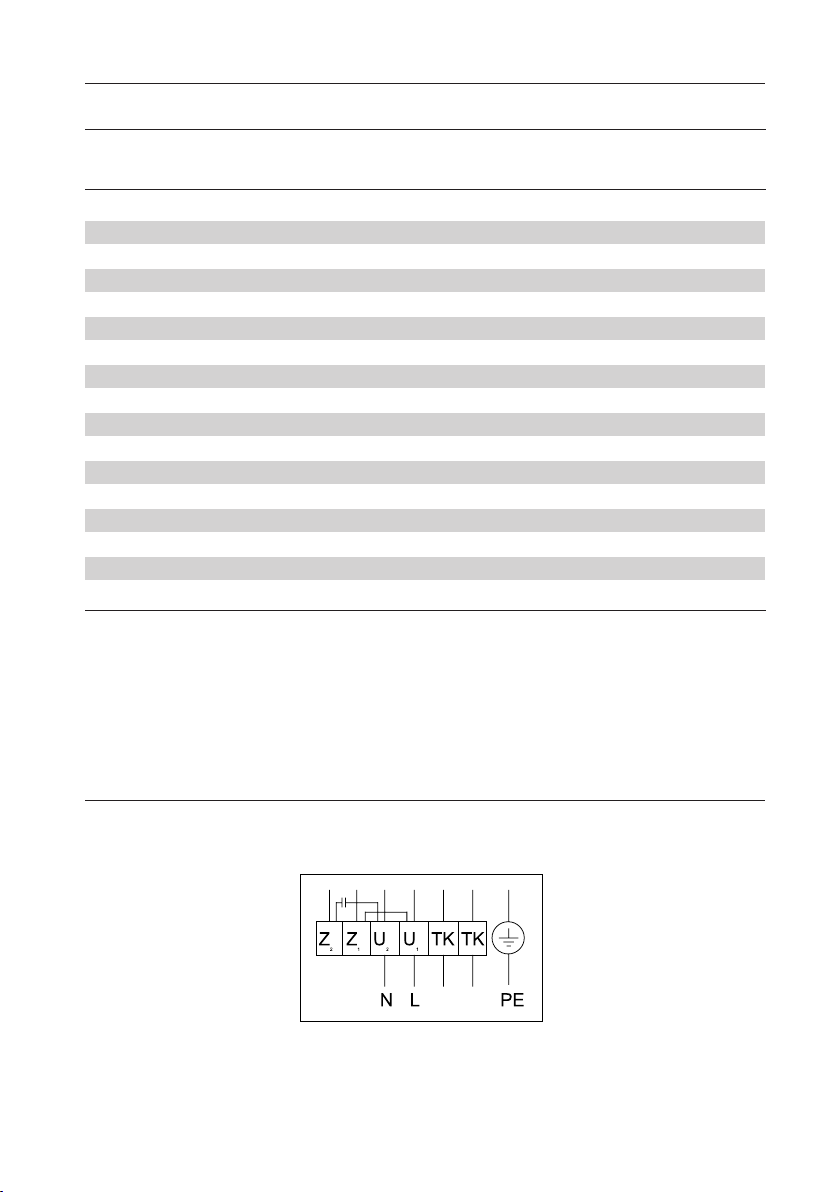
1~230V
Y - 3~400V
Δ - 3~400V

9
[3]
[4]
1~230V
Y - 3~400V
Δ - 3~400V
1~230V
Y - 3~400V
Δ - 3~400V
A (mm) B (mm) C (mm) H (mm)
MDV 311 560 470 435 330
MDV 355 720 618 595 400
MDV 400 720 618 595 435
MDV 450 900 748 665 475
MDV 500 900 748 665 495
MDV 560 1150 1010 939 590
MDV 630 1150 1010 944 626

10
[5]
[6]
h1
h1
500
650
650
700
13
23
25
47
M
M6
M10
M10
M10
G
345
505
565
835
F
710
874
900
1200
E
395
555
625
895
D
330
450
535
750
Codenr.
5996323
5996325
5996327
5996329
Type
311
355/400
450/500
560
kg
h
25
30
30
30
z x d
6 x 7
6 x 9
6 x 9
8 x 9
d1
285
438
438
605
D1
256
402
402
569
D
306
464
464
639
Codenr.
5996343
5996345
5996345
5996349
Type
311
355/400
450/500
560
h2h3

11
[7]
[8]
H
2
4
6.5
H
156
220
255
z x d
6 x 7
6 x 9
8 x 9
d1
285
438
605
D1
256
402
569
D
306
464
639
Codenr.
5996383
5996385
5996389
Type
311
355/500
560
kg
h
25
30
30
30
z x d
6 x 7
6 x 9
6 x 9
8 x 9
d1
285
438
438
605
D1
256
402
402
569
D
306
464
464
639
Codenr.
5996363
5996365
5996365
5996369
Type
311
355/400
450/500
560
h2h3

MARK BV
BENEDEN VERLAAT 87-89
VEENDAM (NEDERLAND)
POSTBUS 13, 9640 AA VEENDAM
TELEFOON +31(0)598 656600
FAX +31 (0)598 624584
www.mark.nl
MARK EIRE BV
COOLEA, MACROOM
CO. COR (IRELAND)
PHONE +353 (0)26 45334
FAX +353 (0)26 45383
sales@markeire.com
www.markeire.com
MARK BELGIUM b.v.b.a.
ENERGIELAAN 12
2950 APELLEN
(BELGIË/BELGIQUE)
TELEFOON +32 (0)3 6669254
FAX +32 (0)3 6666578
www.markbelgium.be
MARK DEUTSCHLAND GmbH
MAX-PLANC -STRASSE 16
46446 EMMERICH AM RHEIN
(DEUTSCHLAND)
TELEFON +49 (0)2822 97728-0
TELEFAX +49 (0)2822 97728-10
www.mark.de
MARK POLSKA Sp. z o.o
UL. AWIA 4/16
42-200 CZE˛STOCHOWA (POLS A)
PHONE +48 34 3683443
FAX +48 34 3683553
www.markpolska.pl
S.C. MARK ROMANIA S.R.L.
STR. LIBERTA
˘TII Nr. 117
TÂRGU MURES, 540190
(ROMANIA)
TEL/FAX +40 (0)265-266.332
info@markromania.ro
www.markromania.ro
MARK BALTIC SIA
STARTA IELA 1
RIGA, LV-1026
(LATVIA)
TEL +371 6737 8416
FAX +371 6737 8417
info@markbaltic. u
www.markbaltic. u
Table of contents
Languages:
Other Mark Industrial Equipment manuals