Preinstallation manual
ersion: 1
Page: 6 of 15
Date: 22.02.2023
PRE-INSTALLATION BY THE CUSTOMER
Pre-Installation of the machine at the site must be carried out by the owner/operator.
Machine owner/operators are responsible for the physical installation, utility connections, and CO
2
supply required to put
a new machine into service.
For an overview of a typical dry ice production system, refer to "Dry Ice Production System" on page 6.
Production Space Requirements
•Adequate ventilation, natural or forced, must be provided to prevent the build-up of CO
2
during production.
•A system to monitor CO
2
levels that will alert personnel when CO
2
levels become too high and pose a danger.
•The machine shall be sheltered from the wind and weather and operate in an environment with an ambient
temperature between 5°C and 43°C (41°F and 109°F).
•The machine must be placed on a horizontal, concrete floor with adequate load carrying capacity.
•The physical distance from the pelletizer to walls, columns or any firm/solid object in the must not be less than
1 meter
Liquid CO
2
Supply System
Cold Jet recommends the supply line for the liquid CO
2
from the storage tank to the pelletizer to be direct (with limited
bends) and well insulated. This will help prevent the formation of gas and maintain the temperature of the liquid CO
2
thus
improving the performance of the pelletizer.
It is the responsibility of the installer of the liquid CO
2
supply system to determine the best supply line route and the
insulation needed.
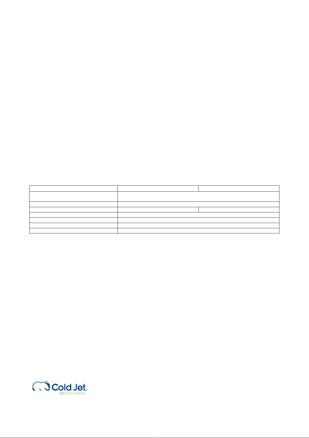
Liquid CO
supply systems PE50 PE80
Optimum performance range 16-18 bar, -24° to -26° C (232-290 psi, -11°F to -15°F)
Pelletizer design pressure / PR setting
2
2
2
(3.0 in) Industrial Insulation
NOTE: If the liquid CO
2
supply line is serving more than one pelletizer, other CO
2
consuming machinery, or is longer than
25 m (82 ft) the owner should consult with the CO
2
piping contractor for an optimal design for a stable and gas-free liquid
CO
2
supply to the pelletizer.
NOTE: For CO
2
tank installation and the liquid CO
2
supplier the recommended supply pressure settings are 16-18 bar, -
24°C to -26°C (232-290 psi, -11°F to -15° F) for optimized output performance and quality. The liquid CO
2
quality in use
must meet general purity requirement of commercial industrial/food grade specifications and must be free of oil and have
a purity of minimum 99.9%. For optimum performance and high-density pellets quality the water (H
2
O) content should
not exceed 35 ppmv and not be less than 5 ppmv - or equivalent to a dew point temperature of -66°C to -51°C (-86.8°F
to -59.8°F). If only very dry CO
2
is present please contact Cold Jet for optimal special extrusion process design and settings.
Please note that the CO
2
tank capacity must always be in proportion to the actual dry ice pellet production rate! (it takes
about 2,5 kg of LCO
2
to produce 1 kg of dry ice)