Indeco IHC250 User manual

Note: This manual is written in English. It is for use only by people that can read, speak and understand
English. In addition, the operators of the attachment (compactor) must also read, speak and understand
English.
IHC250
COMPACTOR MANUAL
YOUR PARTNERS IN DEMOLITION

2
Compactor Manual
3 WARRANTY
4 PREFACE
5 DECLARATION OF CONFORMITY
6 I SAFETY INFORMATION
Precautions 6-9
Safety Decals 10
Airbore Noise 11
12 II TECHNICAL SPECIFICATIONS
IHC250 12-13
14 III EXPLODED VIEW AND PARTS LIST
IHC250 14-15
18 IV HYDRAULIC MOTOR
Relief and Check Valve Operation 16-17
16 V COMPACTOR INSTALLATION
Preping the Carrier 18
Setting Up Compactor 19
Trouble Shooting 20
Compactor Installation Record 21
20 VI COMPACTOR OPERATION Initial & Normal Operation
21 VII COMPACTOR MAINTENANCE (Daily, Weekly, 500 Hours)
22 VIII COMPACTOR ECCENTRIC
Assembly Procedure 24
Cross Section 25
TABLE OF CONTENTS

3
REV 8/26/2014
INDECO NA 135 Research Drive Milford, CT 06460
Standard New Compactor Limited Warranty
INDECO N.A. warrants New Indeco Compactors to be free of defects in materials or workmanship subject to
the following terms and conditions.
1) Warranty period shall be 12 months from date of rst installation.
2) This Warranty covers Labor as listed in the INDECO Flat Rate Schedule at 75% of the Distributors
shop labor rate.
3) This Warranty covers Compactors used in accordance with published INDECO maintenance and
operation procedures.
4) This warranty does not cover failures determined by INDECO to be due to lack of
lubrication, improper installation, poor maintenance or improper operation.
5) This warranty does not cover the replacement of Wear Items.
The following parts are considered to be Wear Items:
Shock Absorbers
6) This Warranty does not cover the replacement of service items during the course of normal
maintenance.
The following parts are considered Service Items:
O-rings Seals
7) This warranty does not cover loss of operating time, loss of use or other consequential damages
while the Compactor is out of service.
8) The repair or replacement of parts during the warranty period does not prolong this warranty.
9) This Warranty does not cover, or include, items sold with, or attached to, the Compactor.
Examples: Grease Pumps, Hydraulic Kits and Hoses.
10) Use of Non INDECO OEM Spare parts will terminate this warranty.
11) Altering or modifying of the Compactor without the written approval by INDECO will terminate this
warranty and any obligations under this warranty.
12) Warranty Registration: INDECO assumes no liability for warranty request submitted for products
for which a New Product Warranty Registration form has not been completed and submitted
to INDECO within 60 days from the time of rst installation of the Compactor. Any warranty
request submitted for a product for which INDECO does not have a New Product Warranty
Registration form on le will be denied.
INDECO does not authorize any other person or company to assume its liability in connection
with the sale or use of its products. WAR-0010-CREV 01-01-10
3 WARRANTY
4 PREFACE
5 DECLARATION OF CONFORMITY
6 I SAFETY INFORMATION
Precautions 6-9
Safety Decals 10
Airbore Noise 11
12 II TECHNICAL SPECIFICATIONS
IHC250 12-13
14 III EXPLODED VIEW AND PARTS LIST
IHC250 14-15
18 IV HYDRAULIC MOTOR
Relief and Check Valve Operation 16-17
16 V COMPACTOR INSTALLATION
Preping the Carrier 18
Setting Up Compactor 19
Trouble Shooting 20
Compactor Installation Record 21
20 VI COMPACTOR OPERATION Initial & Normal Operation
21 VII COMPACTOR MAINTENANCE (Daily, Weekly, 500 Hours)
22 VIII COMPACTOR ECCENTRIC
Assembly Procedure 24
Cross Section 25
WARRANTY

4
Compactor Manual
Manufacture and address:
Indeco North America
135 Research Drive
Milford Connecticut, 06460
U.S.A.
We declare under our sole responsibility that the product described as:
Machine description: Hydraulic compactor
Make: Indeco
Type: IHC250
Serial number: /
Complies with the requirements of the following directive:
Machinery Directives 98/37
Standards considered:
EN 21200-1, EN 12100-2
Date January 1, 2010
Chief Executive Ocer,
Signature
DECLARATION OF CONFONFORMITY

5
REV 8/26/2014
Congratulations on your purchase of this ne INDECO product. To best utilize the advanced
technology engineered into our attachments, we recommend you take the time to famil-
iarize yourself with this manual and the attachment. The information in this manual will
ensure long life, high productivity and minimum downtime from this attachment. Because
we want you to be pleased with your decision to purchase our products, compactor owners
should strictly adhere to the information and technical specications contained within this
manual.
The INDECO Hydraulic Compactor is simply a machine, and like any other machine, is de-
signed to perform within specied guidelines. The compactor takes the hydraulic energy
created by the carrier pumps (excavator, tractor loader backhoe, etc.) and converts this
energy into mechanical or kinetic energy. Therefore, the perfect match of hydraulic compac-
tor to carrier is essential in order to produce maximum performance of the compactor. If the
hydraulic energy (oil pressure, oil ow and return oil pressure between carrier and the com-
pactor) is outside the INDECO specications contained herein, then the compactor’s me-
chanical energy will also be incorrect. Statistics show that 90% of all compactor problems
can be traced back to incorrect mechanical or hydraulic installation to the carrier.
While every attempt has been made by INDECO to manufacture a superior product, we
cannot install the compactor. It is up to the dealer to ensure that compactors are installed
within the enclosed correct parameters for their particular carrier.
To further ensure maximum productivity and longevity of INDECO compactors,
we recommend:
• Adherence to INDECO’s daily, weekly and annual compactor maintenance
programs (enclosed)
• Regular replacement of carrier hydraulic lters (especially in dusty conditions)
• Always check compactor circuit ows and pressures when the carrier is changed
• Annual checks of compactor circuit ows and pressures
If problems with the compactor do occur, we have made every attempt to include any even-
tuality in this Owner’s Manual. Most problems can be easily remedied due to the cause-
and-eect nature of these machines. We have also done our best to ensure correctness of
the information within. However, the manufacturer reserves the right to update this manual
subject to the technological development of the product and service.
PREFACE

6
Compactor Manual
• The dealer must instruct user on proper and safe operation
before delivery of this compactor.
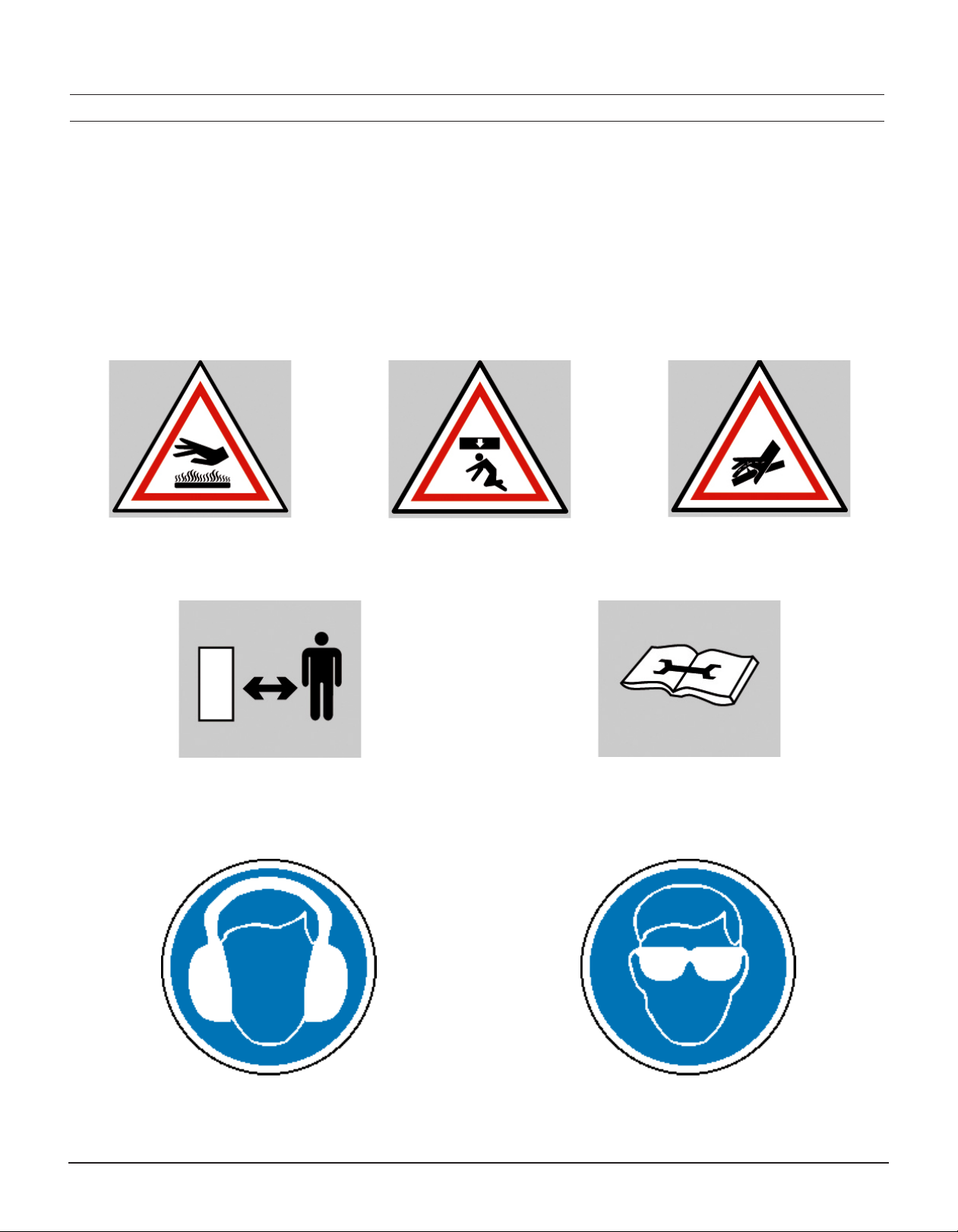
• Wear safety glasses, hard hat and noise protection while
operating compactor.
• Operate compactor only while inside of cab of machine.
• Keep all personnel well clear of machine and compactor
while in operation.
• Install a safety protection device between operator and
compactor.
• Use common sense when using this compactor. Flying stone
chips can injure or even kill.
Safety Precautions
Before operating this INDECO Hydraulic Compactor, please read carefully the
enclosed information. If you have any questions consult your INDECO dealer
for more information.
I SAFETY INFORMATION

7
REV 8/26/2014
Carefully read the following safety precautions. Make sure you fully under-
stand them. Failure to follow a safety warning or recognize and rectify a
safety hazard could result in injury of death to you or others around you. In
general, always use common sense in your work habits and keep your tools
and equipment in good operating condition.
Use trained personnel
Allow only trained personnel to operate or service this equipment. Read
and understand all safety precautions listed in the Indeco manual and in
the Carrier manual.
Flying objects or high-pressure uid hazards
Do not operate Indeco equipment with personnel in the immediate proxim-
ity of the equipment because of possible ying objects of high-pressure
uid hazards. The operator’s compartment should have the necessary
protective guards to prevent entry of ying or falling objects.
Wear correct safety protection
Verify that all personal wear protective headgear, eye protection and steel toe boots.
In dusty conditions, wear a respirator to protect against dust.
Do not wear loose tting clothing or jewelry while working on the machine.
Pay attention to your hands when mounting the compactor
Keep your ngers clear when inserting mounting pins. Do not use your ngers to
“feel”pin alignment. Unexpected boom or equipment movement could result in injury
and possible loss of your ngers. Instruct the operator to touch the controls only when
instructed.
I SAFETY INFORMATION

8
Compactor Manual
Relieve system pressure prior to working on equipment
Escaping uid under pressure can penetrate the skin causing serious
injury.
To avoid any risk, be sure to relieve the pressure before disconnecting
hydraulic lines. Consult the operator’s manual of the carrier for the proper
procedure for relieving pressure.
Important checkpoints before operation
√ Tighten all hydraulic ttings before applying pressure.
√ Keep hands and body away from pinholes and nozzles that eject
uid under high pressure.
√ Do not use your hands to search for leaks. Use a piece of paper.
Operation and maintenance precautions
Never activate the compactor unless the operator is in full control of the carrier and is
seated in the operator’s seat.
Do not operate the compactor above 180°F (82 C) hydraulic oil temperature.
Do not make any alterations to the compactor without authorization from Indeco
Product Support Department.
Make frequent visual inspections of fasteners, attaching pins, hoses and rubber
isolators.
Use caution when torquing fasteners, do not over torque. Adhere to SAE torque
specications only. A previously overstress part may fail later.
I SAFETY INFORMATION
Precautions

9
REV 8/26/2014
Major compactor components are heavy. Always use an adequate lifting device.
Never mount the compactor on a carrier that cannot adequately handle the
compactor weight.
For nighttime operation, the carrier should oer adequate lighting for safe operation
during compacting, repositioning of transporting (European harmonized standard
EN-500-0 paragraph 5.1).
Never use the compactor as part of a lifting device, additional weight could cause the
carrier to tip over or cause damage to the compactor components
Be cautious of ying metal particles when striking any hardened parts with a hand
held tool.
Operate the compactor aware of the eects the vibrations may have on trench walls
and never operate the compactor in a trench with personal working nearby in the
trench at the same time.
Never service or work on the compactor in an open trench of other unsafe area.
Always clean up oil spills.
Do not over compact near buried utilities or foundations; serious damage to utilities
or foundations could result.
Keep personnel clear of the full range of swing, reach, height, depth of carrier boom
while operating or positioning the compactor. During standby periods, always lower
carrier boom so the compactor rests rmly on the ground and turn o the carrier
engine.
Make sure that a window of protective screen is in place on the carrier to fully protect
the operator against ying objects.
I SAFETY INFORMATION
Precautions
10
Compactor Manual
Maintain safety decals
Always replace any safety or warning decals that become damaged of illegible. Replace
all safety of warning decals when repainting the equiment. These decals are available
from your Indeco dealer or from Indeco.
I SAFETY INFORMATION
Safety Decals

11
REV 8/26/2014
Statement of conformity with Directive 98/37/EC
Indeco North America, 135 Research Drive, Milford Connecticut, USA, as manufacturer
and keeper of technical documentation, declares under its own responsibility that the
Indeco Compactor, model IHC250 conforms with the essential health and safety require-
ments of framework directives 98/37/EC and successive modications, has the follow-
ing measured sound levels;
SOUND POWER LEVEL (MEASURED)
Continuous A-weighted sound pressure level at workstations
Exceeds 70 dB (A) at 38.1 meters (125 feet)
Sound power level emitted by machinery where the equivalent continuous A-weighted
sound pressure level at workstations. Exceeds 85 dB (A) at 13.7 meters (45 feet)
1-18-2010 PTU, IHC150 compactor
I SAFETY INFORMATION
Airbore Noise
12
Compactor Manual
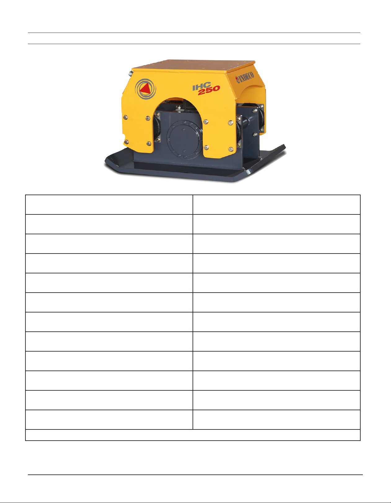
II TECHNICAL SPECIFICATIONS
IHC250
Carrier weight: 20,412-45,360 kg.
45,000 – 100,000lbs
Operating weight 996 kg
2,196 lbs
Height 785 mm
31.0 in
Width 889 mm.
35.0 in
Base Plate 889 mm x 1207 mm
35.0 in x 47.5 in
Base Plate Thickness 38 mm
1.50 in
Oil Supply Range 189-265 l/min
50-70 GPM
Maximum Operating Pressure 170 bar
2,500 psi
Maximum Back Pressure 7 bar
100 psi
Force @ Maximum Frequency 16,090 kg
35,473 lbs
Frequency 30-37 Hz
1,800-2,200 vpm
Reservoir Capacity
(85/90W Gear Oil)
9 l.
2.46 gal.
NOTE: Dimensions are nominal and are for reference only

13
REV 8/26/2014
PAGE LEFT
INTENTIONALLY BLANK

14
Compactor Manual
III EXPLODED VIEW AND PARTS LIST
IHC250
Ref # Qty Description Part #
1 1 Base Plate Assembly CM-250-B-C
2 1 Bearing Carrier (opposite motor) CM-250-BSBR-C
3 1 Eccentric CM-250-ECCA-C
4 1 Bearing Carrier (motor side) CM-250-BSBR-C
5 2 Eccentric Bearing VC9337000
6 1 Snap Ring VC9100200
7 1 Motor VC306930
8 2 Bolt ½”- 13 x 1.25” HW-HC8217
936 Washer ½” HW-39754
10 18 Bolt ½”- 13 x 1.50” HW-30114
11 2 Bolt 5/8”- 11 x 1.50” HW-8264
12 2 Washer 5/8” SAE G8 HW-FWA206
13 2 Reservoir Plug HW-14196
7
1211
4
5
3
15
13
2
98
910
6
10 9
14

15
REV 8/26/2014
III EXPLODED VIEW AND PARTS LIST
IHC250
17
18
19
19
16
15
20
21
23
24
22
Ref # Qty Description Part #
15 1 Bracket Top CM-250-TB-ASM
1Hose Kit IHC-250 Hose Kit Long-R
16 2 Bulkhead Fitting HF2041-1616
17 1Hose Lower Motor Port to Left Front Bulkhead Fitting HH-250-38US
18 1 Hose Front Motor Port to Right Front Bulkhead Fitting HH-250-27US
19 2 Clamp Kit HW-FF593-16
20 4 Isolator VC9338000
1 Bolt Kit, Isolator HWIHC-250-ISO
21 16 Shock Absorber Bolt - ¾”- 10 x 2.5 HW-8293
22 76 Washer - ¾” FLAT SAE G8 HW-FW-207
23 32 Lock Nut - ¾”- 10 SAE G8 HW-NS-107
24 16 Shock Absorber Bolt ¾”- 10 x 2.25d HW8292

16
Compactor Manual
IV HYDRAULIC MOTOR
Relief and Check Valve Operation
Release/Check
Valve
Optional Case Drain
Port

17
REV 8/26/2014
The IHC250 hydraulic motor is equipped with a relief valve that limits the maximum operating pressure of
the system. The check valve allows hydraulic oil to bypass from the return side of the motor to the supply
side of the motor. This is a safety feature to prevent premature failure of the motor if the compactor is shut-
o abruptly at high speed (full ow).
The case drain only needs to be connected when the circuit-return pressure exceeds the maximum allowable
pressure. Install a hose from the case drain port on the motor to the hydraulic tank on the carrier.
NOTE: The Motor Relief Valve is preset at the factory. For any service issues with the valve, contact the
Indeco North America Service Department.
IV HYDRAULIC MOTOR
Relief and Check Valve Operation

18
Compactor Manual
V COMPACTOR INSTALLATION
Installation Procedures for INDECO Hydraulic Compactors
Prepping the Carrier.
Step one: Installing the Flow meter
Install a Hydraulic Flow-meter into the Auxiliary Circuit that will be used to run the Compator.
The Flow meter should be installed in place of the Compactor and not in line with the
Compactor. Also tee a pressure port into the return line if your Flow meter does not have
a separate gauge on its Outlet.
Step two:
With the Restrictor-valve on the Flow-meter turned to the fully open position, (fully closed on
machines with closed center Hydraulics.) Start the machine and run at ½ to ¾ throttle.
Step three: Heating the Hydraulic oil.
Engage the auxiliary circuit and turn the Flow-meter Restrictor-valve until the Flow-meter
pressure gauge reaches approximately 1500 psi. Continue to run the machine until
the hydraulic oil reaches an operating temperature of at least 150 degrees Farenhiet
or 66 degrees Celsius.
* Write this temperature on line F1 of the Compactor Installation Record on page 4.
The following steps should be done with engine rpm’s set at full throttle.
Step four: Setting the Circuit relief.
When the Hydraulic oil has reached operating temperature, turn the Flow-meter
Restrictor-valve in until the pressure no longer rises on the Flow-meter pressure gauge. This
is the current setting of the relief valve for this auxiliary circuit. If the pressure setting
of the relief valve is not in spec, procede as follows. Using the pressure gauge on
the Flow meter reset the circuit relief valve to between 500 and 800 psi above the operating
pressure of the Compactor you are installing.
* Write this pressure on line F2 of the Compactor Installation Record on page 4.
Compactor Circuit Relief Settings
IHC250: 2500 psi
Step ve: Setting the operating pressure.
Using the Flow-meter Restrictor-valve reset the pressure on the Flow meter gauge to the
operating pressure of the Compactor to be installed.
* Write this on line F3 of the Compactor Installation Record on page 4.
Compactor Operating Pressures
IHC250: 2500 psi

19
REV 8/26/2014
Step six: Checking the Flow
With the Flow meter pressure gauge set at the operating pressure of the Compactor, read
the Oil ow on the Flow-meter ow gauge. This must be with in the range of the Compactor
you are installing.
Compactor Flow Specications
IHC250 50-70 gpm
Step seven: Setting the ow.
If the Flow is not within the specied range for the Compactor being installed, it must be ad
justed to within spec. Depending on the Auxiliary circuit being used, ow may be adjusted
several dierent ways. Consult the carrier manufacturer or auxiliary kit manufacturer for the
proper procedure for adjusting the ow.
* After setting the ow, write it on line F4 of the Compactor Installation Record on page 4.
Step eight: Checking the Backpressure.
With the ow properly adjusted and the Flow-meter pressure gauge still set to the operating
pressure of the Compactor being installed, read the gauge, which is teed into the return line.
This is the Backpressure reading for the circuit.
* Write this pressure on line F5 of the Compactor Installation Record on page 4.
Compactor *Maximum* Back pressures
IHC250 100 psi
If the Backpressure reading is too high, there is too much restriction in the return circuit.
A case drain must be installed to prevent damage to the motor.
Doing the following can decrease Return circuit pressure.
1) Increase the size of the Return hoses and tubes.
2) Make sure the return line runs directly back to tank and not back
through the valve.
3) Make sure any return lters are clean.
4) Remove elbows and/or tight bends from the return circuit.
5) Make sure there are no kinks in the return tubes or hoses.
Setting up the Compactor
Step nine: Check oil level in reservoir
To check oil level, remove 3/8” NPT plug from the side of the oil reservoir on the base plate
assembly. The operating oil level should be ush with the bottom of the plughole.
V COMPACTOR INSTALLATION
Installation Procedures for INDECO Hydraulic Compactors
Table of contents


