Osaka AD 10 User manual

OSAKA –AD 10 –OPERATING INSTRUCTIONS –V1 –PAG. 1
ALARMS / EVENTS DISPLAY -
SIGNALING DEVICE
AD 10
Operating Instructions –V1
www.osakasolutions.com
FOREWORD
This manual contains the information
necessary for the product to be installed
correctly and also instructions for its
maintenance and use; we therefore
recommend that the utmost attention is paid to
the following instructions and to save it.
This document is the exclusive property of
OSAKA SOLUTIONS which forbids any reproduction and
divulgation , even in part, of the document, unless expressly
authorized.
OSAKA SOLUTIONS reserves the right to make any formal or
functional changes at any moment and without any notice.
Whenever a failure or a malfunction of the device may cause
dangerous situations for persons, thing or animals, please
remember that the plant has to be equipped with additional
devices which will guarantee safety.
OSAKA SOLUTIONS and its legal representatives do not
assume any responsibility for any damage to people, things or
animals deriving from violation, wrong or improper use or in
any case not in compliance with the instrument’s features.
INDEX
1
INSTRUMENT DESCRIPTION
1.1
GENERAL DESCRIPTION
1.2
FRONT PANEL DESCRIPTION
2
PROGRAMMING
2.1
STANDARD MODE PARAMETERS PROGRAMMING
2.2
PARAMETER PROTECTION USING THE PASSWORD
2.3
CUSTOMIZED MODE PARAMETER PROGRAMMING
(PARAMETERS PROGRAMMING LEVEL)
2.4
RESET PARAMETERS TO DEFAULT VALUE/LEVEL
3
INFORMATION ON INSTALLATION AND USE
3.1
PERMITTED USE
3.2
MECHANICAL MOUNTING
3.3
ELECTRICAL CONNECTIONS
3.4
ELECTRICAL WIRING DIAGRAM
4
FUNCTIONS
4.1
INPUTS CONFIGURATION
4.2
DISPLAY OPERATION
4.3
OUTPUT AND BUZZER CONFIGURATION
4.4
SILENCE ALARMS AND AKNOWLEDGEMENT
MEMORIZED ALARMS
5
PROGRAMMABLE PARAMETERS TABLE
6
PROBLEMS , MAINTENANCE AND GUARANTEE
6.1
SIGNALLING
6.2
CLEANING
6.3
GUARANTEE AND REPAIRS
7
TECHNICAL DATA
7.1
ELECTRICAL DATA
7.2
MECHANICAL DATA
7.3
MECHANICAL DIMENSIONS, PANEL CUT-OUT AND
MOUNTING
7.4
FUNCTIONAL DATA
1 - INSTRUMENT DESCRIPTION
1.1 - GENERAL DESCRIPTION
The model AD 10 is an Alarms/events signalig device.
The Alarms / events are shown on the 3 digit display and can be
detected by 10 digital inputs for voltage free contacts or voltage (24
VAC / VDC) whose operation is completely configurable.
The instrument can also be equipped with an internal relay and a
buzzer that is the sound system for alarms.
1.2 - FRONT PANEL DESCRIPTION
1 - Key SET : Used for programming the function parameters (hold
pressed for 5 sec.)
In programming mode is used to enter in parameters edit mode and
confirm the values. In programming mode it can be used together
with the UP key to change the programming level of the
parameters.
2 - Key DOWN : In programming mode is used for decreasing the
values to be set and for selecting the parameters.
In normal mode it can also used for the aknowledgement/reset of
memorized alarms.
3 - Key UP : In programming mode is used for increasing the
values to be set and for selecting the parameters. In programming
mode can be used togetherwith Key SET to change parameters
level.
4 –Key : In normal mode lets you can be uset to scroll quickly
alarms messages bypassing the time "t.td"
In programming mode can be used to come back in normal mode
(hold for 2 sec.).
5 - Led SET : In normal mode it serves to indicate when a key is
pressed. In programming mode indicates the programming level of
the parameters.
6 - Led OK : When “t.dS” = oF indicates that no Alarms/events are
in progress
7 - Led ALARM : Indicates the Alarms/events status: active (on),
silenced or memorized (flashing)
8 - Led Out : Indicates the output status
9 - + AL: Indicates more than one active Alarms/events

OSAKA –AD 10 –OPERATING INSTRUCTIONS –V1 –PAG. 2
2 -PROGRAMMING
2.1 - STANDARD MODE PARAMETERS PROGRAMMING
To access the instrument’s function parameters when password
protection is disable, press the Key SET and keep it pressed for
about 5 seconds, after which the display will visualised the code
that identifies the first parameter.
Using the UP and DOWN keys, the desired parameter can be
selected and pressing the P key, the display will alternately show
the parameter code and its setting that can be changed with the UP
and DOWN keys.
Once the desired value has been set, press the Key SET again: the
new value will be memorised and the display will show only the
code of the selected parameter.
Pressing the UP and DOWN keys, it is possible to select another
parameter and change it as described.
To exit the programming mode, do not press any key for about 30
seconds, or keep the key pressed for 2 sec. until it exits the
programming mode.
2.2 - PARAMETER PROTECTION USING THE PASSWORD
The instrument has a parameter protection function using a
password that can be personalised, through the “t.PP” parameter.
If one wishes to have this protection, set the password number
desired in the parameter “t.PP”.
When the protection is activate, press the P key to access the
parameters and keep it press for about 5 seconds, after which the
display will show “r.P” .
At this point press P, the display show “0”, using the UP and
DOWN keys, set the password number programmed and press the
Key SET.
If the password is correct, the display will visualise the code that
identifies the first parameter and it will be possible to program the
instrument in the same ways described in the previous section.
Protection using a password can be disabled by setting the
parameter “t.PP” = oF.
Note: If the Password gets lost, just swith off and on the instrument
supply, push P key during the initial test and keeping the key
pressed for 5 seconds.
In this way it’s possible to have access to all the parameters, verify
and modify the par. “t.PP”.
2.3 - CUSTOMIZED MODE PARAMETER PROGRAMMING
(PARAMETERS PROGRAMMING LEVEL)
The password protection hides all the configuration parameters
behind a factory set password to avoid unwanted changes being
made to the programming of the controller.
To make a parameter accessible without having to enter the
password when “t.PP” password protection is activate follows this
procedure.
Enter the programming using the Password “t.PP” and select the
parameter which is desired to be accessible with no password
protection.
Once the parameter has been selected, if the SET led is blinking,
this means that the parameter is programmable by entering the
password (it’s then “protected”) if it’s instead on, this means the
parameter is programmable without password (not protected).
If you want to change the accessibility of the parameter push P
key, keep it pressed and press together also the key UP.
The led SET will change its state indicating the new access level of
the parameter (on = not protected; blinking = protected by
password).
In case some parameters are not protected, when one tries to have
access at the programming, the display will show all the
parameters not protected and the par. “r.P” (through which will be
possible to have access to the “protected” parameters.)
2.4 - RESET PARAMETERS TO DEFAULT VALUE/LEVEL
The instrument allows the reset of the parameters to values
programmed in factory as default.
To restore to the values of default the parameters set the value -48
to “r.P” password request.
Once confirmed the password with the Key SET the display it
shows "---" for 2 sec. therefore the instrument effects the
parameters reset.
3 - INFORMATION ON INSTALLATION AND USE
L 3.1 - PERMITTED USE
The devices are made as measuring and regulating
equipment in accordance with EN60730-1 norm for
operation up to an altitude of 2000 mts.
The use of equipment for standard applications not
expressly provided in norm cited above, should
provide all measurement and adjustments necessary
protection.
The equipment must be adequately protected and away from
liquids, dust, grease and dirt. They must be accessible only with the
use of a right tool and safety system (except the front).
The devices can NOT be used in dangerous environments
(flammable or explosive) without adequate protection.
It is recalled that the installer must ensure that the norm for
electromagnetic compatibility is respected after implantation in the

OSAKA –AD 10 –OPERATING INSTRUCTIONS –V1 –PAG. 3
installation of equipment, eventually using the right filters if is
needed.
In case of failure or malfunction of measuring and control
equipment that can create dangerous situations or damage to
persons, things, animals or products (defrost food or changes in
their ideal state), it is recalled that the facility should be equipped
with electronic devices or electromechanical safety and warning
system.
They should be placed outside the measuring and control
equipments, possible protective devices, responding to specific
safety requirements that are covered by the norm of the product or
suggest the common sense.
For your own safety, is highly recommended fulfilling the
instructions provided above.
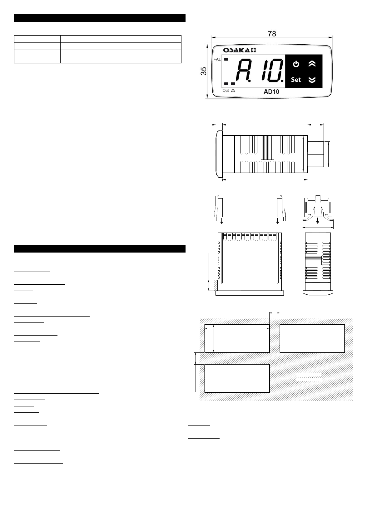
3.2 - MECHANICAL MOUNTING
The instrument, in case 78 x 35 mm, is designed for flush-in panel
mounting. Make a hole 71 x 29 mm and insert the instrument, fixing
it with the provided special brackets. We recommend that the
gasket is mounted in order to obtain the front protection degree as
declared. Avoid placing the instrument in environments with very
high humidity levels or dirt that may create condensation or
introduction of conductive substances into the instrument. Ensure
adequate ventilation to the instrument and avoid installation in
containers that house devices which may overheat or which may
cause the instrument to function at a higher temperature than the
one permitted and declared. Connect the instrument as far away as
possible from sources of electromagnetic disturbances such as
motors, power relays, relays, solenoid valves, etc.
3.3 - ELECTRICAL CONNECTION
Carry out the electrical wiring by connecting only one wire to each
terminal, according to the following diagram, checking that the
power supply is the same as that indicated on the instrument and
that the load current absorption is no higher than the maximum
electricity current permitted. As the instrument is built-in equipment
with permanent connection inside housing, it is not equipped with
either switches or internal devices to protect against overload of
current: the installation will include an overload protection and a
two-phase circuit-breaker, placed as near as possible to the
instrument, and located in a position that can easily be reached by
the user and marked as instrument disconnecting device which
interrupts the power supply to the equipment. It is also
recommended that the supply of all the electrical circuits connected
to the instrument must be protect properly, using devices (ex.
fuses) proportionate to the circulating currents. It is strongly
recommended that cables with proper insulation, according to the
working voltages and temperatures, be used. Furthermore, the
input cable of the probe has to be kept separate from line voltage
wiring. If the input cable of the probe is screened, it has to be
connected to the ground with only one side. We recommend that a
check should be made that the parameters are those desired and
that the application functions correctly before connecting the
outputs to the actuators so as to avoid malfunctioning that may
cause irregularities in the plant that could cause damage to people,
things or animals.
3.4 - ELECTRICAL WIRING DIAGRAM
Inputs for Free voltage contacts model version.
19
7
O U T
161413 15
CNO
17
NC
18
21 3 4 5 6
IN P U T S
222120 2423
108 9 1211
S U P P L Y
di1 di2 di3 di4 di5 di6 di7 di8 di9 di10
O u t: 8 A -A C 1 (3 A -A C 3 )/2 50 V A C B U Z Z E R
IN T E R N AL
X 31 L
Inputs for voltage signal (24 VAC/VDC) model version
di4
O u t: 8 A -A C 1 (3 A -A C 3 )/2 50 V A C
NC
16
O U T
431 2
13
X 31 L
1514
C
di1 di2 di3
S U P P L Y
di10
11
23
98 1065 7
1817
NO
19
IN P U T S
2120 22
di6di5 di7 di8 di9
12
24
IN T E R N A L
B U Z Z E R
2 4 V A C /V D C
(V D C : + -)
4 - FUNCTIONS
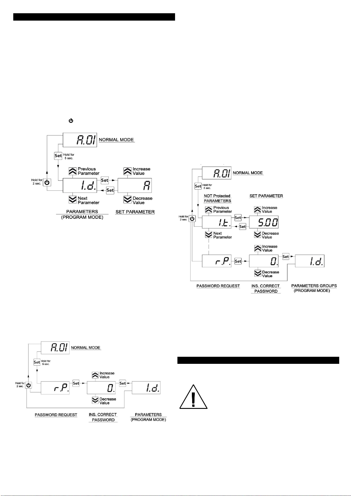
4.1 - INPUTS CONFIGURATION
Each signal is detected by the status change of an input that can
be configured to work through the following parameters:
“1.d” , “2.d”, “3.d” etc: determine the letter preceding the number
for that inputs must be reported as active signal. These parameters
are used to distinguish messages of some inputs like report alarms
(eg, A.01, A.02) from others that may signal errors (eg E.03, ""
E.04) or others who may signal functions in progress (eg F.05 ","
F.06)
“1.L” , “2.L”, “3.L” etc: determine the logic operating of the digital
inputs. If the input signal the event should contact closure
connected to the parameter should be programmed = no, vice
versa if you must report it to the opening of the contact connected
to the parameter should be programmed = nc.
“1.t” , “2.t”, “3.t” etc: allow to delay (up to a maximum of 99min
and 50sec.) the action of each inputs
“1.o” , “2.o”, “3.o” etc: Can establish whether the event should
turn on the internal buzzer or other alerts through output relay.
These parameters allow the buzzer to tie the activation and / or
relay output to some reports only considered serious (eg. alarms or
errors) that do not require other reports (eg. reports of functioning
or minor anomalies).
Parameters can be programmed:
= 0 - no signal
= 1 - signal only by buzzer
= 2 - signal only by output
= 3 - signal by buzzer and by output
“1.A” , “2.A”, “3.A” etc: Can establish whether the reporting on
the event should be memorized and therefore remain active even
when the digital input is deactivated. When an event is memorized
the label signal is flashing to indicate the condition of memorized
event.
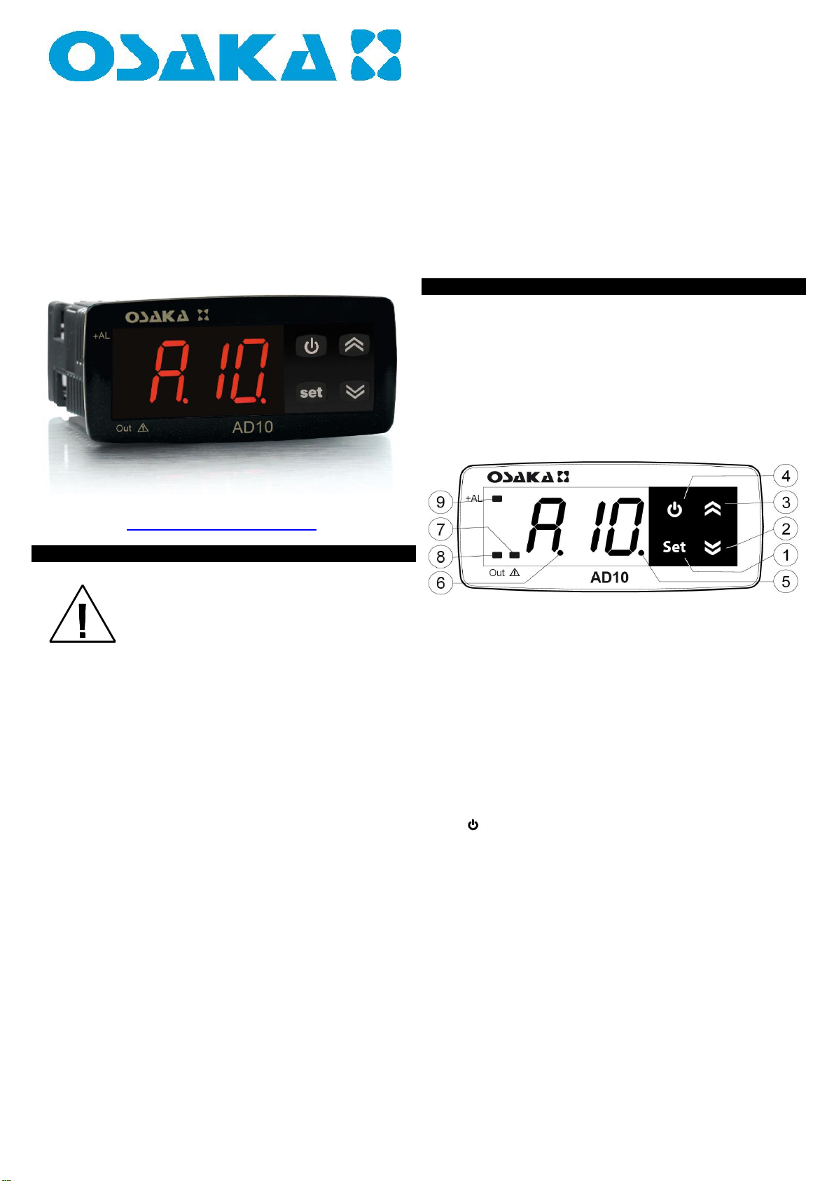
4.2 - DISPLAY OPERATION
Through par. "t.dS" it’s possible to set the standard display
visualization with no Alarms/events signal.
If programmed = oF, the display visualization with no Alarms/events
signal is off except the separationled between letter and number.
If programmed = no.A display in the absence of Alarms/events
signal showing the label “no.A”.
If one event is active, the display always shows only the message
scheduled to report.
If more events are active led +AL is lit to indicate that there are
more alerts the operator and the display shows either all labels with
interval programmed at par. "t.td”.
By pressing and releasing key it’s possible to skip time "t.td" and
and quickly view all active alerts.
AD 10
AD 10

OSAKA –AD 10 –OPERATING INSTRUCTIONS –V1 –PAG. 4
4.3 - OUTPUTS AND BUZZER CONFIGURATION
The instrument output can be configured to activate via the
parameters "1.o", "2.o", "3.o" etc.. = 2 or 3.
The output can be configured by par. “t.tA” for the following
functions:
= At - to control a silenceable alarm device through a contact that
is normally open, and then closed when the alarm sounds
= AL - to control an alarm that cannot be silenced through a
contact that is normally open and closed when the alarm sounds.
= An - to control an alarm with a memory function through a contact
that is normally open and closed when the alarm sounds (see
alarm memory by par. 1.A” , “2.A”, “3.A” etc).
= -At - to control a silenceable alarm device through a contact that
is normally closed, and then open when the alarm sounds.
= -AL - control an alarm that cannot be silenced through a contact
that is normally closed and open when the alarm sounds.
= -An - to control an alarm with a memory function through a
contact that is normally closed and open when the alarm sounds
The buzzer can be configured to activate via the parameters "1.o",
"2.o", "3.o" etc.. = 1 or 3.
The reporting of the Alarm/event through the buzzer and output can
be delayed the time set in par. "t.to.
This allows using the display message (which is delayed by the par.
"1.t", "2.t", "3.t" etc..) As a pre-alarm signal and the buzzer/output
signal as a delayed alarm signal.
4.4 - SILENCE ALARMS AND AKNOWLEDGEMENT
MEMORIZED ALARMS
The buzzer (if enable) is activated in alarm and can be disabled
(alarm silencing) manually by pressing any key of the instrument.
If the output is configured as alarm silenced (t.tA "= At) when
ativated it’s also can switched off by pressing any key
The action of silencing the buzzer and the output is common to all
alarms.
Any condition of alarm/event active it is expected to signal (buzzer
and / or output) is indicated with the ALARM led on while the alarm
silenced condition is indicated by the ALARM led flashing.
The instrument offers the possibility of arranging the alarm memory
function via the parameters “1.A” , “2.A”, “3.A” etc = y.
If ,par. “1.A” , “2.A”, “3.A” etc = n the instrument cancels the alarm
signal when the alarm status ends, if instead it is programmed =y ,
the instrument maintains the alarm/event label flashing when the
alarm/event status ends.
To cancel the alarm memory signal, press and release key DOWN
when the label of alarm/event memorized is on the display.
Deletion of memorized alarms must be performed for each alarm.
If the output is configured to operate as an memorized alarm (t.tA
"= An) it will be activated at the first alarm/event and will be
disabled when all the memorized alarms/events have been deleted.
5 - PROGRAMMABLE PARAMETERS TABLE
Here below is a description of all the parameters available on the
instrument.
Par.
Description
Range
Def.
Note
1
1.d
Input 1 letter label
message
A / E / C / F
A
2
1.L
Function logic of input
1
no = norm. opened
nc = norm. closed
no / nc
no
3
1.t
Delay input 1
oF/ 0.01 ÷ 9.59
(min.sec ) ÷
99.5
(min.sec.x10)
oF
4
1.o
Output/Buzzer
activation by input 1
0 = no act.
1 = buzzer only
2 = output only
3 = buzzer + output
0 / 1 / 2 / 3
0
5
1.A
Memory input 1
y / n
n
6
2.d
Input 2 letter label
message
A / E / C / F
A
7
2.L
Function logic of input
2
no = norm. opened
nc = norm. closed
no / nc
no
8
2.t
Delay input 2
oF/ 0.01 ÷ 9.59
(min.sec ) ÷
99.5
(min.sec.x10)
oF
9
2.o
Output/Buzzer
activation by input 2
0 = no act.
1 = buzzer only
2 = output only
3 = buzzer + output
0 / 1 / 2 / 3
0
10
2.A
Memory input 2
y / n
n
11
3.d
Input 3 letter label
message
A / E / C / F
A
12
3.L
Function logic of input
3
no = norm. opened
nc = norm. closed
no / nc
no
13
3.t
Delay input 3
oF/ 0.01 ÷ 9.59
(min.sec ) ÷
99.5
(min.sec.x10)
oF
14
3.o
Output/Buzzer
activation by input 3
0 = no act.
1 = buzzer only
2 = output only
3 = buzzer + output
0 / 1 / 2 / 3
0
15
3.A
Memory input 3
y / n
n
16
4.d
Input 4 letter label
message
A / E / C / F
A
17
4.L
Function logic of input
4
no = norm. opened
nc = norm. closed
no / nc
no
18
4.t
Delay input 4
oF/ 0.01 ÷ 9.59
(min.sec ) ÷
99.5
(min.sec.x10)
oF
19
4.o
Output/Buzzer
activation by input 4
0 = no act.
1 = buzzer only
2 = output only
3 = buzzer + output
0 / 1 / 2 / 3
0
20
4.A
Memory input 4
y / n
n

OSAKA –AD 10 –OPERATING INSTRUCTIONS –V1 –PAG. 5
21
5.d
Input 5 letter label
message
A / E / C / F
A
22
5.L
Function logic of input
5
no = norm. opened
nc = norm. closed
no / nc
no
23
5.t
Delay input 5
oF/ 0.01 ÷ 9.59
(min.sec ) ÷
99.5
(min.sec.x10)
oF
24
5.o
Output/Buzzer
activation by input 5
0 = no act.
1 = buzzer only
2 = output only
3 = buzzer + output
0 / 1 / 2 / 3
0
25
5.A
Memory input 5
y / n
n
26
6.d
Input 6 letter label
message
A / E / C / F
A
27
6.L
Function logic of input
6
no = norm. opened
nc = norm. closed
no / nc
no
28
6.t
Delay input 6
oF/ 0.01 ÷ 9.59
(min.sec ) ÷
99.5
(min.sec.x10)
oF
29
6.o
Output/Buzzer
activation by input 6
0 = no act.
1 = buzzer only
2 = output only
3 = buzzer + output
0 / 1 / 2 / 3
0
30
6.A
Memory input 6
y / n
n
31
7.d
Input 7 letter label
message
A / E / C / F
A
32
7.L
Function logic of input
7
no = norm. opened
nc = norm. closed
no / nc
no
33
7.t
Delay input 7
oF/ 0.01 ÷ 9.59
(min.sec ) ÷
99.5
(min.sec.x10)
oF
34
7.o
Output/Buzzer
activation by input 7
0 = no act.
1 = buzzer only
2 = output only
3 = buzzer + output
0 / 1 / 2 / 3
0
35
7.A
Memory input 7
y / n
n
36
8.d
Input 8 letter label
message
A / E / C / F
A
37
8.L
Function logic of input
8
no = norm. opened
nc = norm. closed
no / nc
no
38
8.t
Delay input 8
oF/ 0.01 ÷ 9.59
(min.sec ) ÷
99.5
(min.sec.x10)
oF
39
8.o
Output/Buzzer
activation by input 8
0 = no act.
1 = buzzer only
2 = output only
3 = buzzer + output
0 / 1 / 2 / 3
0
40
8.A
Memory input 8
y / n
n
41
9.d
Input 9 letter label
message
A / E / C / F
A
42
9.L
Function logic of input
9
no = norm. opened
nc = norm. closed
no / nc
no
43
9.t
Delay input 9
oF/ 0.01 ÷ 9.59
(min.sec ) ÷
99.5
(min.sec.x10)
oF
44
9.o
Output/Buzzer
activation by input 9
0 = no act.
1 = buzzer only
2 = output only
3 = buzzer + output
0 / 1 / 2 / 3
0
45
9.A
Memory input 9
y / n
n
46
10.d
Input 10 letter label
message
A / E / C / F
A
47
10L
Function logic of input
10
no = norm. opened
nc = norm. closed
no / nc
no
48
10.t
Delay input 10
oF/ 0.01 ÷ 9.59
(min.sec ) ÷
99.5
(min.sec.x10)
oF
49
10.o
Output/Buzzer
activation by input 10
0 = no act.
1 = buzzer only
2 = output only
3 = buzzer + output
0 / 1 / 2 / 3
0
50
10.A
Memory input 10
y / n
n
51
t.dS
Variable visualized
Display normally
operation without
alarms/events active
oF = display off
(except central dp led)
no.A = message no.A
oF / no.A
oF
52
t.td
Time alternating
messages if more than
one
1 ÷ 30 sec.
2
53
t.to
Output/Buzzer delay
oF/ 0.01 ÷ 9.59
(min.sec ) ÷
99.5
(min.sec.x10)
oF
54
t.tA
Output function:
At= Silenceable alarm
(no)
AL= Not silenceable
alarm (no)
An= Memorised alarm
(no)
-At= Silenceable alarm
(nc)
-AL= Not silenceable
alarm (nc)
-An= Memorised alarm
(nc)
At / AL / An / -
At / -AL / - An
AL
55
t.PP
Access Password to
parameter functions
oF ÷ 999
oF

OSAKA –AD 10 –OPERATING INSTRUCTIONS –V1 –PAG. 6
6 - PROBLEMS, MAINTENANCE AND GUARANTEE
6.1 - SIGNALLING
Message
Reason
.
No active Alarms/events signal with “t.dS”=oF
no.A
No active Alarms/events signal with
“t.dS”=no.A
6.2 - CLEANING
We recommend cleaning of the instrument only with a slightly wet
cloth using water and not abrasive cleaners or solvents.
6.3 - GUARANTEE AND REPAIRS
This device has a guarantee in form of repair or replacement by
manufacturing defects in materials of 12 months from the date of
purchase.
OSAKA SOLUTIONS automatically void this guarantee and is not
liable for any damages deriving from:
Use, installation, or use and handling undue, others than
those described above and, in particular, differs from the
safety requirements established by the regulations.
Use in applications, machines or electrical panels that do
not provide adequate protection against liquids, dust,
grease and electric shocks to the installation conditions
made.
The inexperienced handling, and / or alteration of the
product.
The installation / use in applications, machines or
electrical panels do not comply with the valid norm.
In case of defective product under warranty or out of that period, it
should contact the post sales service to perform the necessary
steps. Request document repair "RMA" (by mail or fax) and
complete it, is necessary send the RMA and the device to SAT
OSAKA by method prepaid.
7 - TECHNICAL DATA
7.1 - ELECTRICAL DATA
Power supply: 24 VAC/VDC, 100...240 VAC +/- 10%
Frequency AC: 50/60 Hz
Power consumption: 4 VA approx.
Input/s: 10 digital input for free voltage contacts or voltage inputs
(24 VAC/VDC).
Output/s: 1 relay output SPDT (8A-AC1, 3A-AC3 250 VAC, 1/2 HP
250 VAC, 1/3 HP 125 VAC)
Electrical life for relay outputs: 100000 op.(om. VDE)
Action type: type 1.B (EN 60730-1)
Overvoltage category: II
Protection class : Class II
Insulation: Reinforced insulation between the low voltage part
(supply and relay outputs) and front panel; Reinforced insulation
between the low voltage section (supply and relay outputs) and the
extra low voltage section (inputs); Reinforced between supply and
relay outputs.
7.2 - MECHANICAL DATA
Housing: Self-extinguishing plastic, UL 94 V0
Heat and fire resistance category: D
Dimensions: 78 x 35 mm, depth 64 mm
Weight: 130 g approx.
Mounting: Flush in panel (thickness max. 12 mm) in 71 x 29 mm
hole
Connections: 2,5 mm2screw terminals block or 2,5 mm2
extractable screw terminals block
Degree of front panel protection : IP 65 mounted in panel with
gasket
Pollution situation: 2
Operating temperature: 0 T 50 °C
Operating humidity: < 95 RH% without condensation
Storage temperature: -25 T 60 °C
7.3 - MECHANICAL DIMENSIONS, PANEL CUT-OUT AND
MOUNTING [mm]
64
64
6
6
28
12,5
18,5
14,5
33,5
28
M A X 1 2 m m
P A N E L + G A S K E T
B R A C K E T S
34
R E C O M M E N D E D
P A N E L C U T O U T
29
m in. 1 5 m m
m in. 15 m m
71
7.4 - FUNCTIONAL FEATURES
Display: 3 Digit Red (Blue optional) h 15,5 mm
Software class and structure : Class A
Compliance: ECC directive EMC 2004/108/CE (EN55022: class B;
EN61000-4-2: 8KV air, 4KV cont.; EN61000-4-3: 10V/m; EN61000-
4-4: 2KV supply, inputs, outputs; EN61000-4-5: supply 2KV com.
mode, 1 KV\ diff. mode; EN61000-4-6: 3V), LV 2006/95/CE (EN
60730-1, EN 60730-2-7, EN 60730-2-9)
Table of contents
Other Osaka Measuring Instrument manuals
Popular Measuring Instrument manuals by other brands

B+K precision
B+K precision 467 instruction manual

Challenger Optics
Challenger Optics CO-OLS-MPO12 Interactive operating manual

J-TECH
J-TECH LANEBLADE owner's manual

Extech Instruments
Extech Instruments RPM250W quick start

Electronics International Inc
Electronics International Inc M-1 Operating and installation instructions

Delta-T Devices
Delta-T Devices SWS user manual