Osaka OI 22-V User manual
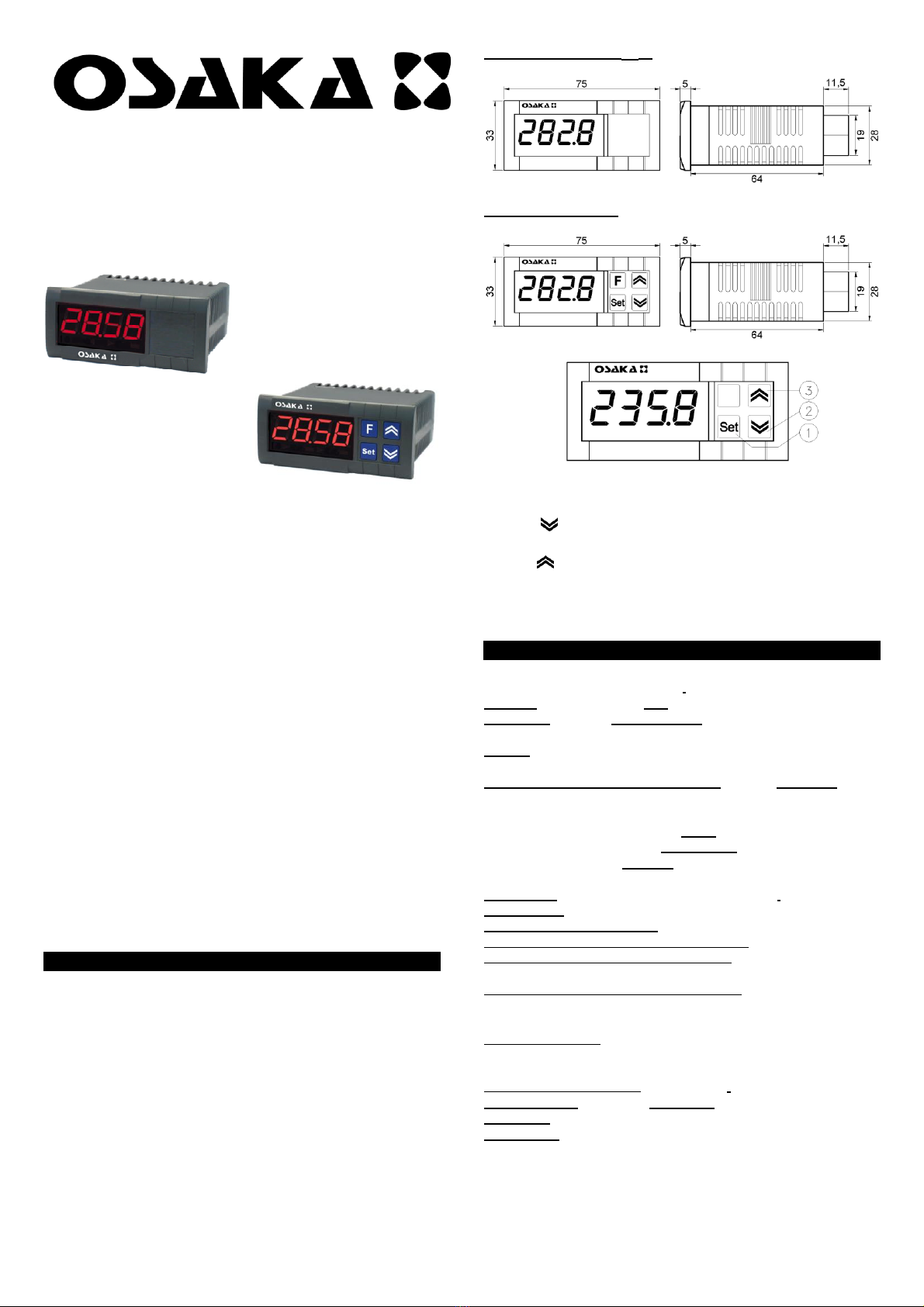
Dimensions and front OI 22
OI 22 -NTC, PT, J / K / S,
mA, V, Dimensions and front
DIGITAL INDICATOR 4 digits
1-Set key: To enter the parameters menu and allows to modify
them.
2-Key: Decreases the programming value of the parameters.
USER MANUAL
INTRODUCTION:
This manual contains the information necessary for correct
installation and instructions for the use and maintenance of the
product, therefore it is recommended that you carefully read
the following instructions.
The same is said for each person or company involved in the
creation of this manual.
This publication is the exclusive property of OSAKA, which
prohibits its absolute reproduction and disclosure, as well as
part of it, unless expressly authorized.
OSAKA reserves the right to make aesthetic and functional
modifications at any time and without prior notice.
3-Key : Increases the programming value of the parameters
meters.
Note: The "F" key is displayed neutral because it does not have any
function.
2 - TECHNICAL DATA
ELECTRICAL CHARACTERISTICS
Feeding: 230 VAC +/- 10%. AC
frequency: 50/60 Hz. Consumption: 3
VA approx.
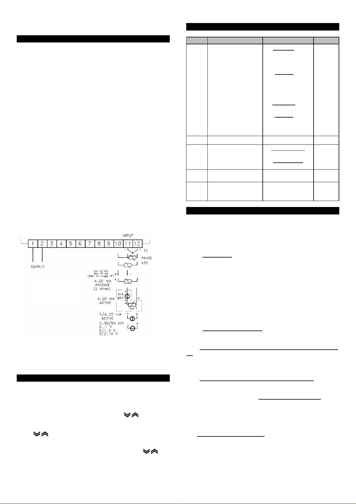
Tickets: 1 input for NTC, PT100 and J / K / S type probes and 0 /
4..20mA and 0..10V signal.
Protection class against electric shock: Class III. Isolation: no
isolation between supply and input.
INDEX
3
4
5
6
7
8
1 GENERAL DESCRIPTION
2 TECHNICAL DATA
INSTALLATION
PARAMETER PROGRAMMING (OI 22 mA, V)
PARAMETER TABLE (OI 22 mA, V)
DESCRIPTION OF THE PARAMETERS (OI 22 mA, V)
TROUBLESHOOTING, MAINTENANCE AND WARRANTY
HOW TO CHANGE THE DECIMAL POINT IN THE OI 12 NTC,
PT100, J / K / S, mA and V
MECHANICAL CHARACTERISTICS Case: Self-
extinguishing plastic UL 94 V0. Dimensions: 33
x 75 mm, depth 64 mm. Weight : 180 g approx.
Installation: Recessed in 29 x 71 mm gap panel.
Connections: Terminal strip for 2.5 mm cabletwo
Frontal protection degree: IP 65.
Ambient operating temperature: 0 ... 55 ° C. Operating ambient
humidity: 30 ... 95 RH% non-condensing.
Transport and storage temperature: -10 ... +60 ° C.
1 - GENERAL DESCRIPTION
The OI 22 model is a digital indicator equipped with 1 input for
NTC, PT100, J / K / S type probes, and mA and V signals. The
process value is displayed on a 4-digit red display.
The front of
the OI 22 mA or V has keys that are used to configure and
modify the range
.
FUNCTIONAL FEATURES
Measurement range: depending on the probe used: NTC = -50..100
ºC; PT100 = -200..850 ° C; J = 0..1000 ° C; K = 0..1370 ° C; S = 0..1760 °
C; 0 / 4..mA, 0..10V.
Display resolution: 1 / 0.1 / 0.01 / 0.001.
Total precision: +/- 0.5% fs. Sampling
frequency: 130 ms.
Accordance: EEC EMC Directive 89/336 (EN 50081-1, EN
50082-1), EEC Directive BT 73/23 and 93/68 (Device that
operates with a nominal voltage lower than 50 VAC and 75 VDC).
OSAKA - OI 22-NTC, PT, JKS, mA, V - USER MANUAL - v2.0K - PAG. 1
5 - TABLE OF PARAMETERS (RO 22)
3 - INSTALLATION Pair. Description Rank Def.
SEnS Signal selection
input (Probe)
PT input:
J / CrAL / S / Ir.J /
Ir.CA / Pt1 / 0.50 /
0.60 / 12.60
Input 0:
J / CrAL / S /
Ir.J / Ir.CA /
ntc / 0.50 / 0.60 /
12.60
MA input:
0.20 / 4.20
Input V:
0.1 /
0.5 / 1.5 / 0.10 /
2.10
MECHANICAL ASSEMBLY: The instrument, in 33 x 75 mm
housing, is designed for panel mounting inside a housing.
Make a 29 x 71 mm hole and insert the instrument, fixing it with
the appropriate bracket provided.
It is recommended to mount the appropriate gasket to obtain the
declared degree of frontal protection.
Avoid placing the internal part of the instrument in places
subject to high humidity or dirt that may cause condensation or
introduce conductive parts or substances into the instrument.
Install the instrument as far as possible from sources that
generate electromagnetic interference such as motors, relays,
solenoid valves, etc.
OFSt Measure deviation - 1999 ÷ 9999 0
ELECTRICAL CONNECTION: Make the connections by
connecting a single conductor per terminal and following the
indicated diagram, checking that the supply voltage is that
indicated for the instrument and that the load on the actuators
connected to the instrument does not exceed the maximum
admissible current. The instrument, designed to be
permanently connected inside a panel, is not equipped with a
switch or internal devices to protect against excess current, it is
recommended to adequately protect all the circuits connected
to the instrument with devices (eg fuses) suitable for the
circulating current. It is recommended to use cables with
appropriate insulation for the running voltages and
temperatures and to position so that the input cable of the
probe is distant from the power cable and other power cables.
dP Number of digits -
summits
Pt1 / Ptc / ntc:
0..1
normal signal:
0..3
one
SSC Lower limit scale
mA / V signal input
- 1999 ÷ FSC 0
FSC Upper limit scale
the input signal
mA / V
SSC ÷ 9999 0
6 - DESCRIPTION OF PARAMETERS (OI 22 mA, V)
The parameters presented in the table above are described
below. Some of them are not displayed on the instrument since
the equipment is not equipped to have them or because the
instrument automatically disables them, if they are not used.
SEnS - Ticket type: Depending on the model we have, we can
select the following probe inputs:
- Thermoresistances: Pt100 IEC (Pt1)
- Thermistors: PTC KTY81-121 (Ptc) or NTC 103AT-2 (ntc)
- Signals in mV: 0..50 mV (0.50), 0..60 mV (0.60), 12..60 mV
(12.60)
- Current signals: 0..20 mA (0.20) or 4..20 mA (4.20)
- Voltage signals: 0..1 V (0.1), 0..5 V (0.5), 1..5 V (1.5), 0..10 V (0.10)
or 2..10 V (2.10).
- Thermocouple: J (J), K (CrAL), S (S) or for infrared sensors
OSAKA IRS series J (Ir.J) or K (Ir.CA)
OFSt - Measure compensation : positive or negative
compensation that we will use to correct small deviations of the
input probe.
SSC - Lower limit of input range for analog signals (mA, mV,
V): Value that the instrument must show on the display when
the signal at the input coincides with the minimum value of the
ranges (0/4 mA, 0/12 mV, 0/1 V or 0/2 V).
FSC - Upper limit of input range for analog signals: Value that
the instrument must show on the display when the signal at the
input coincides with the maximum value of the ranges (20 mA,
50 mV, 60 mV, 1V, 5 V or 10 V). Examples of SSC and FSC: If we
have a 4..20 mA signal, we can establish a display range of
0..100, where the value "0" will coincide with a signal of 4 mA
(SSC) and where the value "100" will coincide with a 20 mA
signal (FSC).
dP - Number of decimal places: Allows you to set the
resolution of the measurement, 1 (0), 0.1 (1), 0.01 (2), 0.001 (3).
For Pt100, PTC and NTC temperature probes the maximum
resolution is 0.1 ° (1).
4 - PARAMETER PROGRAMMING (OI 22)
To access the operating parameters menu, hold down
the “Set” key for approximately 2 seconds until “OPEr”
appears on the display. Press the "Set" key and the
"InP" parameter folder will appear. Press the "Set" key
again to enter the folder and use the keys to
scroll through the parameters. For
modify a parameter press the "Set" key and use the
keys to increase or decrease the value of said
parameter. Press the "Set" key again to confirm. If you
want to modify another parameter, proceed in the
same way. If you want to exit, keep one of the keys
pressed until you exit completely (the measurement
value will be displayed).
OSAKA - OI 22-NTC, PT, JKS, mA, V - USER MANUAL - v2.0K - PAG. 2
7 - PROBLEMS, MAINTENANCE AND WARRANTY
ERROR SIGNALS
The instrument display is used to view instrument error
conditions by displaying the following messages: "E1" - Tr probe
error (E1) interrupted or short-circuited. "o1" - "u1" - Tr (1)
probe input in overrange (o) or in underrange (u). In these
cases, verify the correct connection of the probes with the
instrument and then proceed to verify them.
"EE" - Memory error, in this case check, and if necessary,
reprogram the operating parameters.
MAINTENANCE
It is recommended to avoid using abrasive detergents or
solvents that can damage the instrument.
WARRANTY AND REPAIR
The instrument is warranted for 12 months against construction
faults or material defects. The warranty is limited to the repair
or replacement of the product. The eventual opening of the
casing, the manipulation of the instrument or the use and
installation not in accordance with the instructions will
automatically void the warranty. In the event that the product is
defective within or outside the warranty period, contact OSAKA
to obtain authorization for the shipment. Send the defective
product, accompanied by the indications of the defect found, to
the OSAKA establishment, except for different agreements.
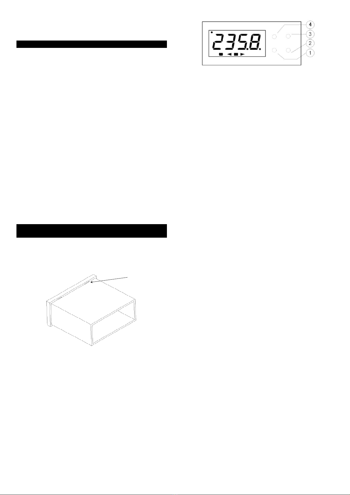
8 - HOW TO MODIFY THE DECIMAL POINT IN THE (OI 12
NTC, PT100, J / K / S, mA and V)
To change the decimal point, first remove the front of the
equipment by inserting a screwdriver and making a slight turn
in the small slots shown in the figure of the equipment casing:
Press the key "1”For about 2 seconds until“ OPEr ”appears on
the display. Press the key "1”And“ InP ”will appear. Press the key
"1”To enter the folder and use the keys “2" Y "3”To scroll
through the parameters. To modify the decimal point, go to the
parameter "dP" and press the key "1”. Use the keys " 2" Y "3”To
increase or decrease the value of said parameter ( on = decimal
point on) and (oF = decimal point off). Press the key "1" to
confirm. To exit, press and hold the “2" Y "3 Until leaving.
OSAKA - OI 22-NTC, PT, JKS, mA, V - USER MANUAL - v2.0K - PAG. 3
This manual suits for next models
7
Other Osaka Measuring Instrument manuals


