WARRANTY AND REPAIR
In the event of a breakdown or malfunction of the equipment,
risk situations and / or damage to persons or property may be
created. Remember that the installation must be equipped with
devices that guarantee safety.
This equipment has a warranty in the form of repair or
replacement, for defects in the manufacture of materials, of 12
months from the date of delivery.
Improper use or manipulation automatically voids said
warranty.
The equipment must be adequately protected from water and dust
according to its application and must be accessible only with the use
of a tool (except the front one).
In the event of a defective product, it is necessary to contact the
after-sales service to carry out the appropriate procedures. (Request
repair document; "RMA”, By mail or fax) and fill it in, it is necessary
to send the RMA and the equipment to SAT OSAKA postage prepaid,
except for other pre-established agreements.
3 - INSTALLATION
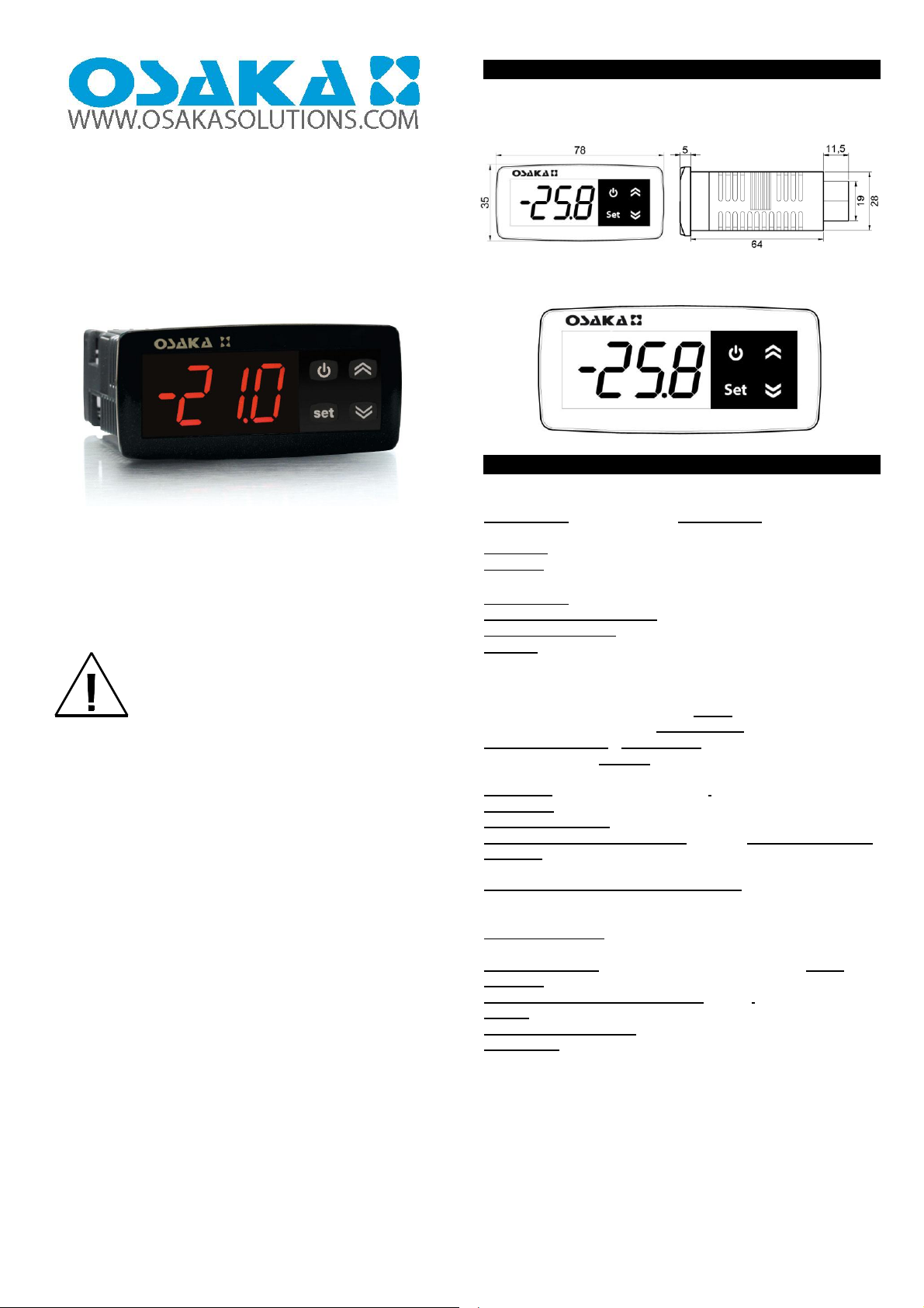
MECHANICAL ASSEMBLY
The 32 x 74 mm box thermostat is designed for wall or wall
mounting through the holes provided in the plastic and
accessible after removing the front part.
Once the equipment is installed, it is recommended to close the
front panel. Avoid placing the thermostat in a place exposed to
high humidity or dust, this can cause condensation or the
introduction of particles or conductive substances. Make sure
that it has adequate ventilation and avoid installing indoors in
hermetic boxes or areas where the temperature exceeds the
technical characteristics of the equipment. Avoid installing the
supply and power cables together with the probe and install
away from equipment that can generate disturbances (electrical
noise) such as motors, fans, frequency inverters, automatic
doors, contactors, relays, solenoids, etc. ...
ELECTRICAL CONNECTION
The thermostat is designed for permanent connection between
equipment, it is not equipped with a switch or internal power
devices for overcurrents or voltages. It is therefore
recommended to install a general switch / disconnector /
magneto-thermal device as close to the equipment and easily
accessible to cut off if necessary, as a safety feature. It is
recalled that appropriate cable must be used to insulate the
voltage, current, temperature and electrical regulations of the
premises, in addition, the probe signal cables must be
separated from the supply and power cables as far as possible
in order to to avoid possible electrical noises, electromagnetic
inductions, which in some cases could be reduced or canceled
with RC filters, ferritic, power, varistors,
It is recommended to check that the equipment configuration
parameters are appropriate for the application before
connecting the actuator cables, loads at the relay output in
order to avoid anomalies or damage.
5 - HOW TO MODIFY THE DECIMAL POINT PARAMETER,
PROBE CALIBRATION AND CHOOSING THE UNIT OF
MEASURE
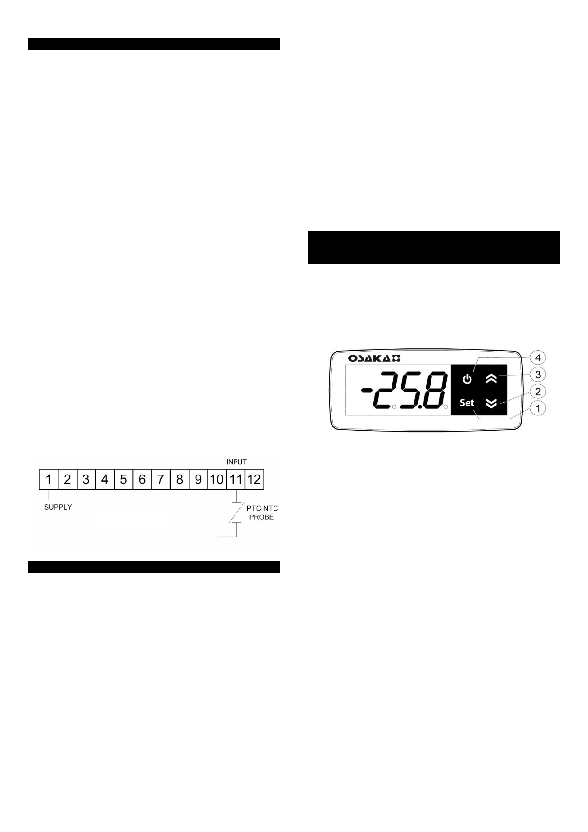
Press the “SET” key for approximately 2 seconds until “OPEr”
appears on the display. Press the “SET” key and “InP” will
appear. Press the “SET” key again to enter the folder and use the
“DOWN” and “UP” keys to scroll through the parameters.
ELECTRICAL CONNECTION DIAGRAM
DECIMAL POINT - Parameter “dP”
To modify the decimal point, go to the parameter "dP" and
press the "SET" key. Use the "DOWN" and "UP" keys to increase
or decrease the value of said parameter. Press the "1" key again
to confirm. To exit, keep the "DOWN" and "UP" keys pressed
until exiting.
PROBE CALIBRATION - Parameter “OfSt”
To modify the decimal point, go to the "OfSt" parameter and
press the "SET" key. Use the "DOWN" and "UP" keys to increase
or decrease the value of said parameter. Press the "SET" key
again to confirm. To exit, keep the "DOWN" and "UP" keys
pressed until exiting.
4 - PROBLEMS, MAINTENANCE AND WARRANTY
ERROR SIGNALS
The instrument display is used to view instrument error
conditions by displaying the following messages: "E1" - Tr probe
error (E1) interrupted or short-circuited. "o1" - "u1" - Tr (1)
probe input in overrange (o) or in underrange (u). In these
cases, verify the correct connection of the probes with the
instrument and then proceed to verify them.
"EE" - Memory error, in this case check, and if necessary,
reprogram the operating parameters.
UNIT OF MEASURE - Parameter “Unit”
To modify the decimal point, go to the "Unit" parameter and
press the "SET" key. Use the "DOWN" and "UP" keys to change
the ºC or ºF unit. Press the "SET" key again to confirm the choice.
To exit, keep the "DOWN" and "UP" keys pressed until exiting.
MAINTENANCE
It is recommended to clean the only with a damp cloth without
detergent or with neutral detergent
OSAKA - OI 22-0 - USER MANUAL - v3 - PAG. 2