OSCILLA SM960-C User manual

ID: 1614 / ver. 210
1
Instructions for Use
Oscilla®SM960-C Clinical Audiometer
Specifications are subject to change without notice
2017-05-15

ID: 1614 / ver. 210
2
Table of contents
1GENERAL DESCRIPTION......................................................................................................................................... 3
2DESCRIPTION OF FRONT PANEL .......................................................................................................................... 4
3DESCRIPTION OF BACK PANEL ............................................................................................................................ 5
4OPERATION.............................................................................................................................................................. 6
4.1 ATTENUATORS........................................................................................................................................................ 6
4.2 INTERRUPTER .......................................................................................................................................................... 7
4.3 OUTPUT SELECTOR.................................................................................................................................................. 7
4.4 INPUT SELECTOR...................................................................................................................................................... 7
4.5 FUNCTION.............................................................................................................................................................. 8
4.6 TALK THROUGH...................................................................................................................................................... 8
4.7 FREQUENCY ........................................................................................................................................................... 8
4.8 ATTENUATOR LOCK................................................................................................................................................. 9
4.9 TAPE/MIC .............................................................................................................................................................. 9
4.10 MEMORY............................................................................................................................................................... 9
4.11 AUDIOGRAM ID ................................................................................................................................................... 10
4.12 SHIFT ................................................................................................................................................................... 10
4.13 PRINT................................................................................................................................................................... 10
4.14 DATA .................................................................................................................................................................. 10
4.15 AUTOMATIC HEARING TESTS .................................................................................................................................. 10
4.16 SETUP.................................................................................................................................................................. 12
5TECHNICAL SPECIFICATIONS.............................................................................................................................. 16
6WARNING AND SAFETY NOTICES................................................................................................................. 18
6.1 WARNING........................................................................................................................................................... 18
6.2 SAFETY NOTICES ................................................................................................................................................ 18
6.3 MAINTENANCE &CALIBRATION ........................................................................................................................ 18
6.4 CLEANING .......................................................................................................................................................... 18
6.5 SHIPPING RECOMMENDATIONS ........................................................................................................................... 18
6.6 DISPOSAL ........................................................................................................................................................... 18
7SYMBOLS .............................................................................................................................................................. 19
8EMC......................................................................................................................................................................... 20
9RESPONSIBILITY OF THE MANUFACTURER ............................................................................................. 22
10 MANUFACTURER ............................................................................................................................................... 22

ID: 1614 / ver. 210
3
1General Description
OSCILLA®SM960-C CLINICAL MEMORY AUDIOMETER is a two channel audiometer with click-free buttons and
sound pressure level between -10 to 120 dB, equipped with thee different types of masking, among others Narrow
Band Masking, which means effective masking.
The device has a built-in memory of 17 audiograms, and the option of connection to PC or printer.
The SM960-C is programmable featuring a range of useful tests including various automatic threshold tests.
Display: The device has four LCD displays, three of them for traditional use: Attenuator and frequency display. The
fourth display, referred to as the VU display, is meant for different purposes, mainly as a VU meter and during
standard use, as an intensity indicator of ex. level of talk back, sensitivity of the microphones etc.
Function
This device can perform clinical hearing tests in order to determine the hearing threshold of a person. It supports
pure-tone and speech and masking.
Intended application
The intended application of the device is to be used within a diagnostic environment operated by ear doctors or
likewise.
Classification
Type 2 - Clinical Audiometer
For additional information refer to the technical specifications.
ID: 1614 / ver. 210
4
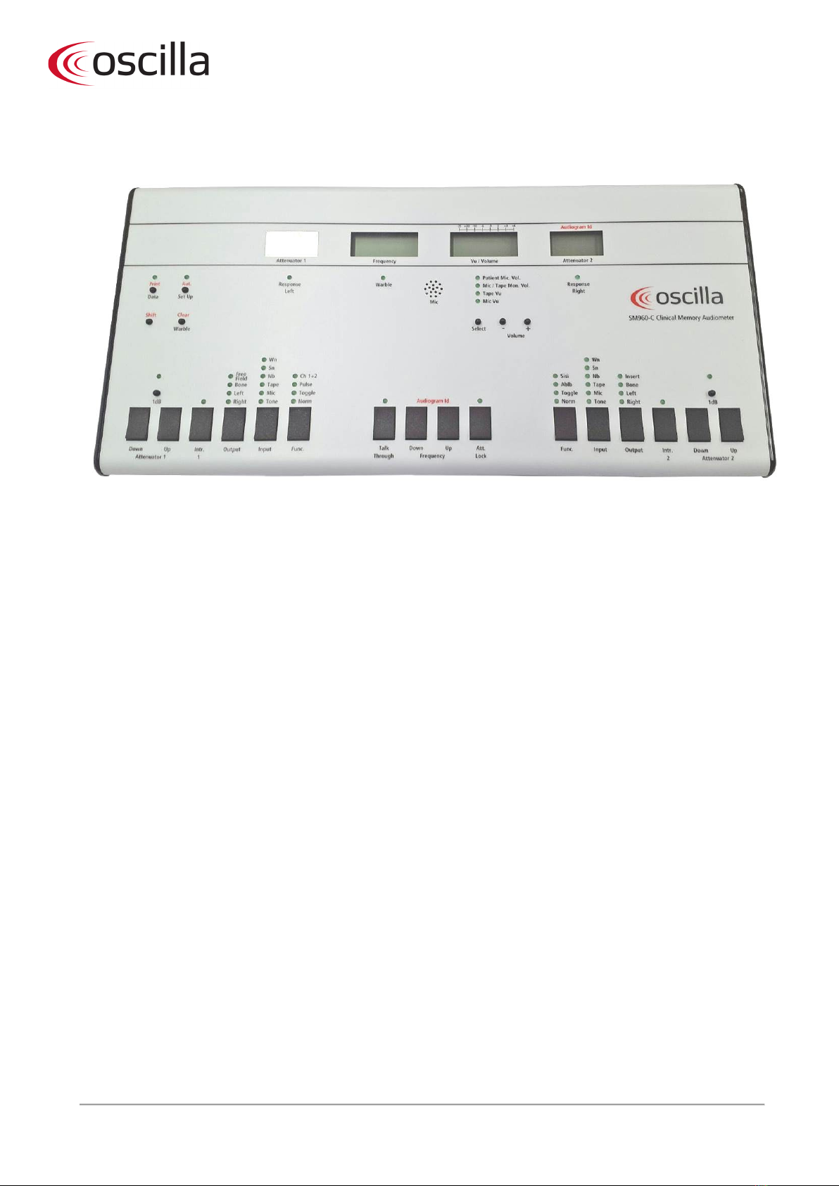
2Description of front panel
Attenuator 1 - The actual sound pressure in dB
Frequency - The actual frequency in Hz
Vu/Volume - VU meter and volume indicator for
speech section
Audiogram Identification - The active audiogram
Attenuator 2 - The sound pressure for channel 2
Print - Prints the active audiogram
Data - Transmits the test results to a connected PC
Aut. - Starts 1 of 3 possible tests
Setup - Enters the setup function
Shift - Select the “RED” functions
Clear - Erase audiogram
Warble - This adds a frequency modulation to the
tone, at a modulation frequency of 5 Hz
Select
- Select the volume or sensitivity to adjust
Volume - Adjust the selected volume or sensitivity
1 dB
-
Change channel 1 attenuator to 1dB steps
Attenuator 1
- Push the DOWN/UP to change
channel 1 sound pressure
Intr. 1 - Sends channel 1 signal to the patient
Output - Selects the output for channel 1
Input - Selects the input for channel 1
Func. - Selects the interrupter mode for channel 1
Talk through - Communicate with the patient
Frequency - Pushing one of the buttons changes the
frequency to the next fixed value
Audiogram Identification - Push one of the buttons
to select which audiogram to be active
Att. Lock
- Makes attenuator 2 follow channel 1
Func. - Selects the interrupter mode for channel 2
Input - Selects the input for channel 2
Output
- Selects the output for channel 2
Intr. 2
- Sends channel 2 signal to the patient
Attenuator 2 - Push the DOWN/UP to change
channel 2 sound pressure
1 dB -Change channel 2 attenuator to 1dB steps

ID: 1614 / ver. 210
5
3Description of back panel
The earphones, bone conductor and patient answer button cables are mounted with jack plugs which are hooked up
to the appropriate sockets on the back side of the device. The power adapter is inserted into the POWER socket at
the back of the audiometer and plugged into an electrical outlet.
When the device is turned on, the version number is shown shortly, and the FREQUENCY display shows 1000 Hz. If
the devices’ memory function is enabled in SETUP, the attenuator displays will show the last used sound levels, or, if
memory is disabled, the attenuators will show 20.
Insert earphone - Mono insert phone
Right - Right earphone
Left - Left earphone
Bone conductor - Bone conductor
Free Field - Free field loudspeaker
Operator headphones - Operator headphone
Line-in - Tape or CD input
Talkback Back microphone - Patient microphone
Patient responder - Patient answer buttons
RS-232 - Connection for PC
Printer - Connection for printer
/
- Device on/off
Power supply - Power connector

ID: 1614 / ver. 210
6
4Operation
If nothing else mentioned, the description will be for both channels.
4.1 Attenuators
By applying light pressure to the DOWN/UP
buttons
the attenuator steps up or down.
The actual sound level can be read in the two attenuator
displays.
Normally the steps are 5 dB, but by means of the 1 dB button the steps can be changed to 1 dB.
Held down for a while, the attenuators will repeat.
The attenuators are click free, meaning that you may change sound level while the attenuators are active, without
loosing the signal. However, there is a reservation to this: Say you start at 60 dB at 1000 Hz and hold down the
interrupter while increasing the hearing level. In this case you will not be able to rise hearing level to 120 dB, without
releasing the interrupter.
This has the following reason:
In order to decrease amplifier noise at low hearing levels, the signal to the earphones is attenuated by 20 dB by a
resistor. When a high level is needed the resistor is shorted by a relay. This must happen while the earphone is silent,
or a loud click will be heard. If the operator wants to increase hearing level near to maximum you need to release the
interrupter, increase hearing level, and activate the interrupter again. The same applies when you want to decrease
from a high to a low level - you also need to release the interrupter. In this case it will be at a sound level 25 dB lower
than when increasing the level.
To be able to increase hearing level without the relay shortening, you must do the following:
An example: Anticipate that the attenuator is set on 40 dB; consequently the relay is switched off. You want to
perform a manual tone decay test which moves over 20 dB and starts at 85 dB. Press the attenuator up to 105 dB (20
dB higher than the starting point) to ensure the relay will short. Now set the attenuator back to 85 dB where you
want the test to start. Because of the 25 dB difference in the relay switching point, the relay will stay shorted. You
may now activate the interrupter and move attenuator from 85 to 105 dB without any cut-offs.
The 1 dB button
By means of the 1 dB button
you may select steps of 1 dB
for the attenuator
.
The light will shine as long as the
1 dB function is active.
As mentioned you may change hearing level while interrupters are active. When the 1 dB steps are active the change
is made over 200 msec. instead of the usual 50 msec. making it impossible to hear any sharp increase of hearing level.
Please note that the attenuator may be a little slow when running 1 dB, and the interrupter is activated.
5 dB:
The 5 dB is performed over 50 msec. smooth as the 1 dB increase, e.g. for tone decay tests.
ID: 1614 / ver. 210
7
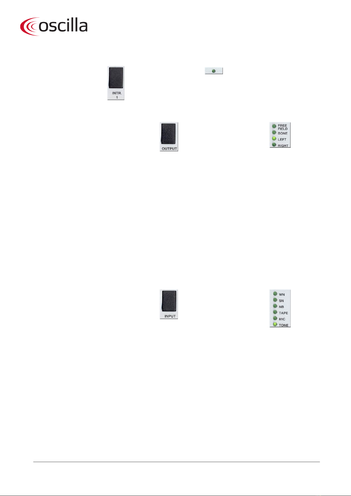
4.2 Interrupter
With the interrupter button
you activate the signal.
The light will shine as long as
the signal
is present.
4.3 Output selector
The output from the device is chosen by means
of the output selector, which allows the choice
of 5 different ways
of output.
The lamps will indicate which
output is selected.
For both channels you may choose:
- Right and left telephone
- Bone conductor
Channel 1:
- Free field
Channel 2:
- Insert phone
The output selector on channel 1 is operated in a special way: By pressing the button you choose between right and
left earphone. To select bone conductor hold down SHIFT while activating the output selector. The bone indicator
lamp will light up, whereas right or left indicator lamp will remain ON.
When you activate the output selector again without SHIFT, you toggle between right and left BONE CONDUCTOR.
The reason is that the device will have to ‘know’ at which side the bone conductor is placed, to get the correct
symbols on the screen and/or on the printout. This also means that the signal will always be through the same output,
no matter if right or left bone conductor is chosen.
To choose FREE FIELD once again you should hold down the SHIFT while activating the output selector. The RIGHT-
LEFT lights will turn off, as there is no option of right or left FREE FIELD.
4.4 Input selector
By means of input selector you choose the input
signal, which gives you 6 different options. May
be used on both channels.
The lamps will indicate which
input is selected.
TONE:
M
IC:
TAPE:
NB:
SN:
WN:
Standard sinus tone for threshold test.
Build
-in microphone meant for either speech
audiometric or for communication to the patient.
The connector marked with “TAPE” on the back of the
device, for either tape
-recorder or CD player.
“Narrow Band” noise for masking.
“Speech Noise” for masking.
“White Noise” also for masking.
For technical reasons: If one channel is on TAPE you can not at the same time choose MIC on the opposite channel.
When performing a standard threshold test channel 2 should be used for masking, if you want to store data.
ID: 1614 / ver. 210
8
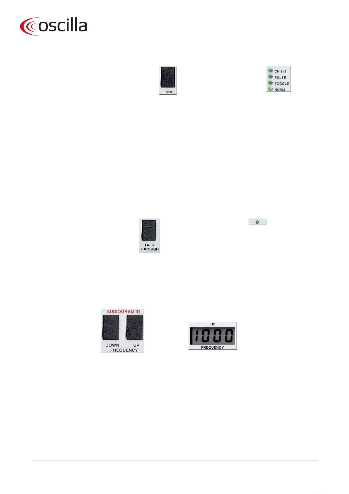
4.5 Function
By activating this button you determine how the
interrupter reacts when activated
.
The lamps will indicate which
mode is selected.
You have the following possibilities on channel 1:
You have the following possibilities on channel 2:
MAN:
Standard operation.
TOGGLE:
Interrupter toggles between active and inactive, when
you push the button.
PULSE:
Enables pulse tone
- push the interrupter to present
the pulse tone.
CH1+CH2:
Simultaneously activation of both interrupters
MAN:
Standard operation.
TOGGLE:
Interrupter toggles between active and inactive, when
you push the button.
ABLB:
Will initiate the ABLB test (see special description).
SISI:
Will initiate the SISI test (s
ee special description).
4.6 Talk Through
The TALK THROUGH button provides a
quick and easy way to communicate
with the patient.
The light will shine as long as
the button is held down.
When holding down the button the MIC signal will be transmitted to both earphones at the same time. Holding
down the talk through button, you may adjust the sound pressure by means of the channel 1 attenuator. Actual
sound level will be shown in Channel 1 display. The set level will be stored for later communication to the patient -
therefore you do not have to adjust sound level for each communication during the test.
Before using the talk through, make sure that the sensitivity of the microphone is on an appropriate level (see
paragraph: Tape/Mic).
4.7 Frequency
With the DOWN/UP
buttons one of the 11
frequencies is selected.
Actual frequency will always be shown in
frequency display.
Holding one of the buttons down the frequency is repeatedly changed to lower (DOWN) or higher (UP) values until
the key is released (see SETUP, MODE 1).

ID: 1614 / ver. 210
9
4.8 Attenuator lock
By means of the ATT LOCK, you may lock
the channel 2 attenuator to the
attenuator on channel 1, but you may still
use channel 2 separately.
The lamp above the ATT. LOCK
lights up when the lock function is
active.
The lock is a one-way lock, which is valuable for masking.
4.9 Tape/Mic
The device has a built-in memory for 17 audiograms. Each audiogram is identified by an ID number from 1 to 17.
This section in the device is used for setting the sensitivity of the build-in microphone as well as the Tape input, and in
addition to set the volume for Talk Back and monitoring.
By means of SELECT you
choose what you want
to change.
The lamps will show
which setting will be
adjusted.
VOLUME + or - for
correction of the set
ting.
Actual setting is shown
in the bottom part of the
VU display.
Following options:
MIC VU
Sets sensitivity for the build
-in microphone. Choose MIC on one of the
input selectors, and adjust to appropriate deflection on the VU display.
TAPE VU
Se
ts sensitivity for TAPE input. Choose TAPE by means of one of the INPUT
selectors, and adjust to appropriate deflection on the VU display.
MIC/TAPE MON. VOL.
Sets sound level in the operator’s earphone. Select MIC or TAPE on one of
the INPUT selectors, an
d then adjust to appropriate sound level.
PATIENT MIC. VOL.
Sets sound level of the patients microphone (talk back), should be adjusted
while the patient is talking.
4.10 Memory
The storage capacity is 17 audiograms each with an ID number between 1 and 17. Following test results will be
stored:
Sound level for LEFT and RIGHT earphone
Sound level for LEFT and RIGHT bone conductor
Sound level for FREE FIELD loudspeaker
Sound level for masking together with earphone
Sound level for masking together with bone conductor
SISI test scores for LEFT and RIGHT earphone
The channel 1 attenuator display will show the stored value for the chosen frequency and output. The channel 2
attenuator will show the masking level, used by either earphone or bone conductor.
ID: 1614 / ver. 210
10
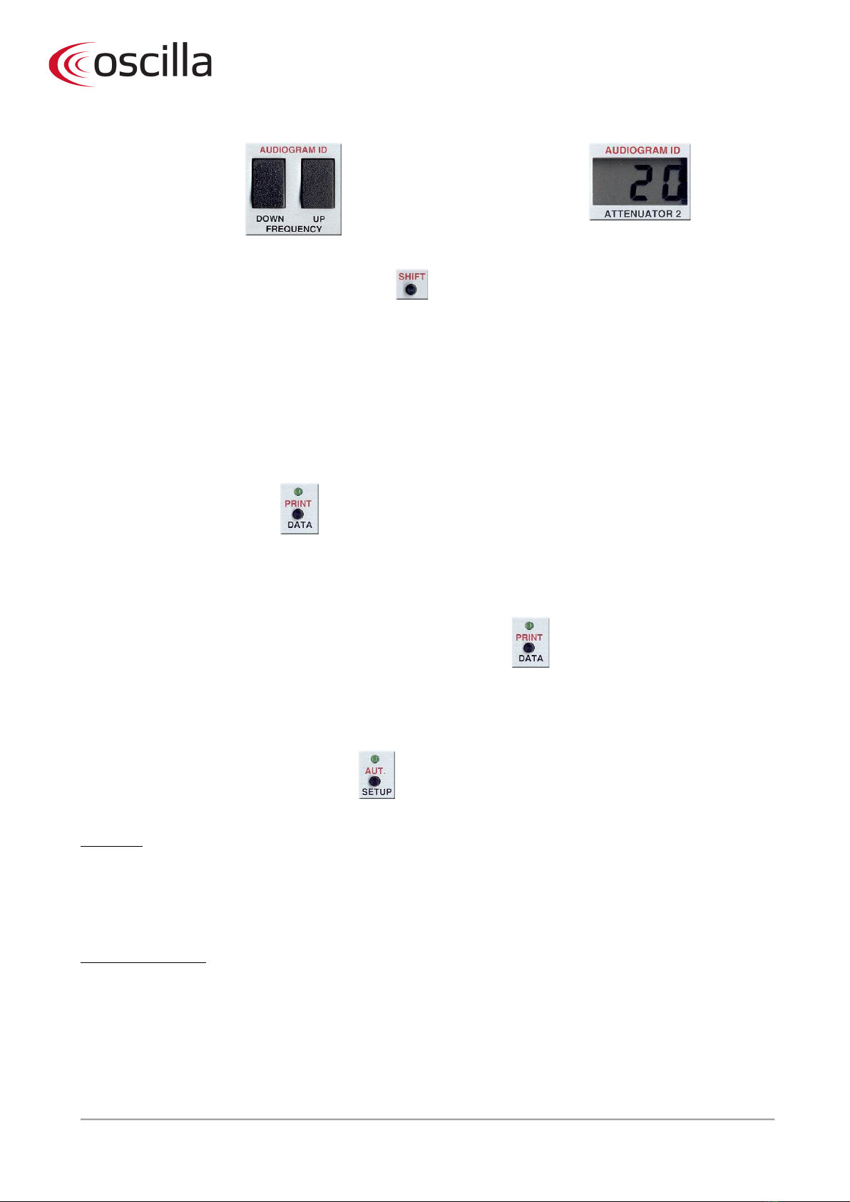
4.11 Audiogram ID
Use the SHIFT + ID
DOWN/UP buttons, to go
through the audiograms
to find one specific test.
The number is shown in the ID
display, which is the same as the
channel 2 attenuator.
4.12 Shift
All function written in red on the front panel is
ac
tivated by using the SHIFT button.
In addition you have the following possibilities:
- Shows actual ID number when held down.
- Changes “direction” of the various features, as they are so called wrap-around. If you hold down the SHIFT and
press SELECT, you will go back-wards instead of forwards, which is practical instead of having to go through all
functions to get the one you want. This options goes for the INPUT selectors as well as the FUNCTION selector and the
channel 2 OUTPUT selector.
4.13 Print
Use the SHIFT + PRINT buttons
to print the active audiogram
to a connected printer.
The light above the button will light up during the printing, and the
program automatically selects the correct symbols. If the printer is not
connected or shows an error
(e.g. out of paper), the light turns off
after
a couple of seconds.
For selection of printer type see special paragraph in setup.
4.14 Data
A push on the DATA button causes the device to transmit the test
results stored in the active audiogram to a connecte
d PC.
Transmission time is 0.2 seconds.
4.15 Automatic hearing tests
The program contains three different automatic tests. To choose between the three types of test, enter the SETUP
function, and change mode 5. See the SETUP section for more information.
Use the SHIFT + AUT. buttons to start 1 of 3
possible tests
The three automatic tests
20 dB test
This performs a quick automatic screening test with fixed sound pressure of 20 dB. The test chooses 1000 Hz, the
sound pressure will be set to 20 dB and increase in steps of 5 dB until the patient responds. Immediately hereafter,
the frequency changes and the sound pressure starts at 20 dB again.
20 dB RANDOM test
This is an extremely useful automatic test. It starts by selecting 1000 Hz, first at the left, then the right ear. It then
randomly selects frequency and channel in the rest of the test until all frequencies has been tested at both channels,
and thereby makes it hard for the patient to ‘cheat’. In both the 20 dB and the 20 dB random test there is a slight
variation in the duration of the tones presented, and the pause between the tones. These variations are also chosen
randomly.
When a 20 dB test is finished

ID: 1614 / ver. 210
11
1. If all frequencies are answered at 20dB, you will hear 1 BEEP after the test, to indicate that all frequencies
have been heard.
2. If one or more frequencies was not responded to at 20 db, you will hear 3 BEEPS and the AUT lamp will
flash, telling you that not all frequencies have been heard. Press the AUT. button to stop the flashing, and go
through the frequencies to see which of them was not heard. All frequencies that displays “20” was heard at
20 dB, and other levels tells you at what level the patient responded. If a frequency was not responded to
even at 80 dB, the attenuator display will flash when this frequency is selected.
Variable automatic test
The frequency is set to 1000 Hz and a tone is automatically given to the left ear at an intensity of 30 dB. As long as
there is no response from the patient to the tone, the intensity will increase 10 dB each time the tone is presented,
until the patient signal button is pressed. For each response the intensity is reduced 5 dB and conversely increased 5
dB when there is no answer.
When the software program has accepted the answer, the frequency is automatically changed to the next level and
the procedure is repeated until all frequencies have been tested for both the left and the right ear.
When the test is completed, the audiometer gives a beep. If some of the frequencies have not been heard, the lamp
above the AUT button will flash. Press the AUT button and check the frequencies. The attenuator display will flash for
the frequencies not heard. It is possible to conduct a manual test for those frequencies.
Please note that for safety reasons the maximum intensity is fixed at 80 dB during the automatic test.
Please note that frequencies left out will not be included in the automatic threshold tests.
SISI test: (Short Increment Sensitivity Index)
In addition to the three automatic tests the SM960-C is equipped with an automatic SISI test. The test has three pulse
amplitudes it operates at, which can be selected while it runs. The three amplitude modes are as follows:
5dB:
The test starts in this mode, and is intended only for familiarizing the patient with the test method. The patient
responses and pulses are not counted in this 5dB mode, and the mode continues until the next mode is selected, or
the test is terminated.
2dB:
This mode presents 20 pulses of 2dB increments before it continues to the 1dB mode. It counts the patient responses,
but does not store the count in memory. If the patient has responded to every pulse, or did not respond to any of
them after 10 pulses, the test will continue to 1dB mode.
1dB:
This presents 20 pulses of 1dB increments. It also counts the patient responses, but this time it is stored in memory as
the test result in percent. This happens when 20 pulses has been presented, or if there was either 0% or 100%
responses to the first 10 pulses.
The patient is allowed to respond within a period of 3 seconds after each pulse. The response lamps will always show
the responses, but they are not counted up if they occur later than 3 seconds after the pulse.
While the test is running, the frequency display is used for pulse counting and the VU display is used for patient
response counting. The channel 2 attenuator display shows the sound level and the pulse increment, when it happens
every 5 seconds.
Using the test:
The test is controlled on the audiometer’s channel 2. When the FUNCTION setting is set to SISI, then the VU will
display changes to show the test results. Also the attenuator to channel 2 is preset to a level 20dB higher than
channel 1. This is just for convenience, as a SISI test is usually performed at 20dB higher level than the patient’s
hearing threshold. The level can be changed freely with the attenuator buttons before the test is started.
After setting the INPUT to TONE and the OUTPUT and FREQUENCY to the desired channel and frequency, the test is
started by pressing the INTERRUPTER. A breef “SISI TEST” is displayed, followed by “5 dB”, to indicate that the 5dB
amplitude mode is running. While the test runs, the ATTENUATOR keys are used to change the amplitude mode. UP

ID: 1614 / ver. 210
12
selects the next mode and DOWN selects the previous. The mode is displayed breefly when changed, and the pulse
and response counters are reset. The test can be terminated manually with the interrupter.
The memory:
Test results are stored in every audiogram, and for every frequency as a percent figure. There is memory for the left
and the right earphone. It is possible to run a SISI test using the bone conductor and the mono insert phone too, but
the results are not stored separately, they use the same memory as left and right. When SISI is selected on the channel
2 function selector, the VU display recalls the stored test results when the frequency and channel is changed. These
results may be erased by pressing CLEAR (with shift). This only clears the single result that corresponds to the currently
selected frequency and channel. When a printout is done, all the SISI test results are shown in a table below the
audiogram.
ABLB: (Alternate Bilateral Loudness Balance)
ABLB involves both channels by activating the two interrupters twice on each channel, in the following way:
INPUT and OUTPUT is selected for both channels. The two attenuators are set on the wanted soundpressure. On the
channel 2 FUNCTION choose ABLB.
To start the test: press the channel 2 interrupter.
Duration of tone as well as the pause in between may be programmed individually, SETUP no. 7.
4.16 Setup
You may individually change the basic function of the SM960-C by programming one or more of the 11 SETUP
functions.
The setup function is entered by
pressing the SETUP button.
Two short beeps will be heard, and the
VU display will show “SETUP”
briefly.
To change between each SETUP mode press the channel 2 attenuator, and selected mode is shown in the channel 2
attenuators display as a figure between 1 and 11.
Mode 1: Frequency selecting
AUDIOGRAM ID
FRE 125-8000 1
FREQUENCY VU/VOLUME ATTENUATOR 2
In this mode you may leave out one or more frequencies. Select the frequency with the frequency buttons, and use
the channel 1 attenuator to include or leave out the selected frequency. The VU display says ON when the frequency
is included and OFF if it is left out.
Mode 2: Tone length
AUDIOGRAM ID
LENG OFF 2
FREQUENCY VU/VOLUME ATTENUATOR 2
The duration of the ON-TIME of the interrupter. To change the ON-TIME, use the channel 1 attenuator. The selected
length is shown in the VU display. Options are: OFF, 0.5, 1.0, or 1.5 second.
If one of the three numbers are programmed the tone will last for this period, no matter how long you press the
interrupter. If the display says OFF, the interrupter is operated manually.
Mode 3: Recall mode

ID: 1614 / ver. 210
13
AUDIOGRAM ID
RCAL ON 3
FREQUENCY
VU/VOLUME
ATTENUATOR 2
Connects or disconnects the storage function. To include or exclude storage capacity press the channel 1 attenuator.
The VU display will show ON or OFF for connected or disconnected. If the memory function is disconnected the device
will operate as a standard manual audiometer, and printer, serial port and automatic tests are not accessible. A special
setting here is “AUTO”. If this is selected, the audiometer will transmit the audiogram to the serial port each time the
channel 1 attenuator is changed. It also transmits when the ID number is changed, and when an automatic test is run,
each time the frequency is changed. Note that the channel 1 attenuator will be acting a bit slow while this “AUTO”
transmit feature is enabled.
Mode 4: Reset
AUDIOGRAM ID
RSET OFF 4
FREQUENCY VU/VOLUME ATTENUATOR 2
Connects or disconnects the RESET option. The programming of this feature is done by means of the channel 1
attenuator, and the VU display says ON or OFF. When reset is ON the tone is disconnected when you change
frequency or channel.
Mode 5: Auto mode
AUDIOGRAM ID
PRNT HP 5
FREQUENCY VU/VOLUME ATTENUATOR 2
By means of programming mode 5 you may choose the type of printer which is connected to the device. Selection is
made by pressing the channel 1 attenuator. The selected printer type is shown in VU display. Options are:
9: Used with most Epson compatible 9 pin matrix printers.
24: Used with most 24 pin printers, and many inkjet printers such as Canon.
PRO: Used with IBM ProPrinters. Some other printers can emulate a ProPrinter.
HP: Used with HP DeskJet and laser printers. Many other laser printers may emulate HP lasers, and will work with this
setting.
Note that printers designed specially for Microsoft Windows will not work when connected directly to the audiometer.
It is, however, perfectly possible to use them together with a PC, when the audiometer is connected to the PC via the
serial port. If you don’t know which ‘language’ your printer works with, you may just try the different settings and see
if it works. There is no risk of damage to neither the printer nor the audiometer by selecting a wrong printer type. You
may also consult the printers’ manual for information about what the printer can emulate.
Mode 6: Auto mode
AUDIOGRAM ID
AUTO RND 6
FREQUENCY VU/VOLUME ATTENUATOR 2
Selecting one of the three automatic tests. In the VU display is shown which of the three automatic tests is selected:
20dB, Random 20dB (RND) or variable (VARI) and the choice is made by means of the attenuator 1 buttons. Please
note that any frequencies left out as a result of programming mode 1, will also be skipped over in the AUTO test.
Mode 7: ABLB test timing
AUDIOGRAM ID
ON 0.6 7

ID: 1614 / ver. 210
14
FREQUENCY VU/VOLUME MASKING LEVEL dB
Programming of ON and PAUSE time for the ABLB test. Select between ON and PAUSE time with the channel 1
interrupter button. The FREQUENCY display will show ON = ON TIME or PAUS = PAUSE. Then use the channel 1
attenuator to select a time between 0.1 and 1 second.
Mode 8: Carriage return on/off
AUDIOGRAM ID
CR ON 8
FREQUENCY
VU/VOLUME
MASKING LEVEL dB
Some printers may not print a full audiogram, or make blank horizontal stripes. This is usually caused by either
sending a carriage return to a printer programmed to automatically return the printhead at a new line (blank stripes
occur), or by sending no carriage return to a printer that expects it (only one line is printed). By means of the channel
1 attenuators you may connect or disconnect carriage return. The VU display will say ON or OFF for connected or
disconnected. This setting has no effect if the printertype (mode 5) is set to HP.
Mode 9: Bone audiogram on/off
AUDIOGRAM ID
BONE ON 9
FREQUENCY
VU/VOLUME
MASKING LEVEL dB
On the printout you may choose to have the bone test results printed in a separate audiogram frame, or have both air
and bone printed in the same frame. By selecting ON in this mode, a separate bone audiogram is printed. If this mode
is on, and no air tests have been performed, only a single audiogram is printed, containing the bone test results. Also,
if no bone results exist in memory, no extra audiogram is printed.
Mode 10: Identification on/off
AUDIOGRAM ID
ID
ON
10
FREQUENCY VU/VOLUME MASKING LEVEL dB
This mode is for enabling or disabling the identification sent to the PC when turning on the device. This must be
turned on for use with the AudioConsole program. If you encounter problems when the device is used to transmit
data to other programs, try turning ID off.
Mode 11: Select supra phones or inserts phones calibration
AUDIOGRAM ID
CALI PHON 11
FREQUENCY VU/VOLUME MASKING LEVEL dB
This mode selects between supra aural earphones or insert phones. The selected type of phones is displayed briefly
when the device is turned on. Select “PHON” if supra aural phones (TDH 39) are used, and “INST” if insert phones
(usually Eartone 3A or 5A) are used. The selection affects the calibration and the maximum output level.
Mode 12:
AUDIOGRAM ID
PP PARA 12
FREQUENCY VU/VOLUME MASKING LEVEL dB
This mode selects if a printer is connected to the parallel port, or the serial port. If you use the Kyosha Thermo printer,
this mode must be set to SERI. This printer is connected to the socket marked “SERIAL” on the audiometer. For
printers with parallel port, select PARA, and connect the printer to the socket marked “PRINTER”.
Finishing programming

ID: 1614 / ver. 210
15
To exit the SETUP, press the SETUP button again. The software program stores the selected settings, until changes are
made.
Reset to DEFAULT values is performed manually by using the below listed values.
Mode 1: All frequencies available.
Mode 2: OFF.
Mode 3: ON.
Mode 4: OFF.
Mode 5: HP.
Mode 6: RND.
Mode 7: ON TIME: 0.6 seconds. PAUSE: 0.3 seconds.
Mode 8: ON.
Mode 9: OFF
Mode 10: ON
Mode 11: PHON
Mode 12 :PARA
ID: 1614 / ver. 210
16
5Technical specifications
Standards compliance: EN 60645-1: 1996
EN 60601-1:1990 + A1:1993 + A2: 1995 + A13:1996
EN 60601-1-2:2002
Classification: Group 1, class A EN 60601-1-2:2002
Medical CE- mark: Inmedico A/S is approved for medical CE marking, by DGM.
Identification number 0543
Transducers: TDH-39 air, B-71 bone (calibrated via mastoid)
Power Supply: 18 VAC, 800mA max.
Adaptor: Primary: 230 VAC, 50/60 Hz, 170mA max.
Secondary: 18 VAC,20 VA, ± 10 %
Environmental Conditions for Operation
Ambient Temperature: +15 to +35 degree Celsius.
Relative Humidity: 30 % to 90 %
Surrounding pressure: 80 kPa to 120 kPa
Environmental Conditions for Storage
Ambient Temperature: -10 to +50 degree Celsius
Relative Humidity: 95% or less (non-condensing)
Surroundings pressure: 50 kPa to 120 kPa
Physical Attributes
Dimensions: 389 (W) x 180 (D) x 55 (H) mm
Parallel port: Automatic printout of complete audiogram, 60/72 dpi.
Serial port:Computer data transmission (RS-232) to patient file. 9600 baud.
Warm-up time: <10 minutes
Included parts: audiometer, Peltor H7A headphones with TDH-39, response button,
bone conductor, power supply, user manual and calibration certificate
Accessories: carrying bag, serial cable, printer cable, AudioConsole software
Measurement specifications
Measurement Method Manual and automatic threshold test with storage of data.
Type of protection against electric shock: Class I equipment
Degree of protection against electric shock: Type B applied part
Degree of protection against liquid penetration: IPO, ordinary equipment
Degree of safety of application in the presence
of flammable anaesthetics:
N/A
Mode of operation: Continuous operation

ID: 1614 / ver. 210
17
Measurement Range
Maximum Intensities:
White Noise: 110 dB (same for all frequencies)
Speech Noise: 115 dB (same for all frequencies)
Measurement Accuracy
Tolerance frequency: ± 1 %.
In/output impedance: Left / Right channel ~ 4,7- 144,7 ohm, Patient response ~ 1 Kohm
Distortion speaker: TDH-39: < 1 %, 4. and higher harmonic + sub harmonic < 0,3 %.
Single signal channel:
Air conductor: ± 4 dB (125 Hz – 4 kHz)
± 5 dB (6 kHz – 8 kHz)
Bone conductor: ± 4 dB (125 Hz – 4 kHz)
± 5 dB (6 kHz – 8 kHz)
Multiple signal channels: ± 1 dB (125 Hz – 4 kHz)
± 2 dB (6 kHz – 8 kHz)
Measurement Durations and Times
Data transmission: RS-232C protocol
Storage space: 17 audiograms
Frequency
Air Bone
Pure Tone Narrow Band
Pure Tone Narrow Band
125
250
500
750
1000
1500
2000
3000
4000
6000
8000
Hz
Hz
Hz
Hz
Hz
Hz
Hz
Hz
Hz
Hz
Hz
80 dB
100 dB
120 dB
120 dB
120 dB
120 dB
120 dB
120 dB
120 dB
110 dB
100 dB
70 dB
90 dB
110 dB
110 dB
110 dB
110 dB
110 dB
110 dB
110 dB
100 dB
90 dB
10 dB
40 dB
70 dB
70 dB
70 dB
70 dB
70 dB
70 dB
60 dB
50 dB
40 dB
0 dB
30 dB
60 dB
60 dB
60 dB
60 dB
60 dB
60 dB
50 dB
40 dB
30 dB

ID: 1614 / ver. 210
18
6 Warning and safety notices
6.1 Warning
•No modifications of the device nor accessories are allowed.
6.2 Safety notices
•Place the audiometer at least 1 meter from the patient.
•Always use accessories supplied by the manufacturer.
6.3 Maintenance & calibration
It is recommended to have the device calibrated every other year by Inmedico A/S or a technician authorised by
Inmedico A/S. Contact your Oscilla®distributor for further information regarding calibration.
6.4 Cleaning
The patient responder and patient headset need to be cleaned on a regular basis for hygienic reasons. Both can be
cleaned with disinfecting wipes or a cloth wrung in lukewarm water with soap or dishwashing liquid. Disconnect the
parts from the audiometer before cleaning. Ensure that they are dry before re-connecting.
6.5 Shipping recommendations
The audiometer should be packed in a manner, which prevents it from being damaged during transportation. For
example, the device can be packed in bubble wrap and shipped in an ordinary cardboard box – or similar.
6.6 Disposal
According to Directive 2012/19/EU (WEEE) and local regulations, the device including accessories can be disposed of
as normal electronic waste.
ID: 1614 / ver. 210
19
7 Symbols
Manu
facturer
Serial number
Catalogue/product number
Caution
Follow instruction for use
Consult instruction for use
Type B applied part
Direct current
Medical device according to Medical Device Directive 93/42/EEC.
Humidity limitatio
n
Atmospheric pressure limitation
Temperature limit
The device must be recycled or disposed of in a proper manner in accordance with the WEEE
Directive 2012/19/EU.

ID: 1614 / ver. 210
20
8 EMC
•SM960-C is an electro-medical device and is therefore subject to special safety precautions. For this reason,
the installation and operating instructions provided in this document must be followed closely.
•Portable and mobile high-frequency communication devices, such as mobile phones, may interfere with the
functioning of SM960-C.
Guidance and manufacturer’s declaration – electromagnetic emission
The device is intended for use in the electromagnetic environment specified below. The customer or the user of the device should
assure that it is used in such an environment.
Emissions test Compliance Electromagnetic environment – guidance
RF emissions CISPR 11
Group 1
This device uses RF energy only for its internal function. Therefore, its RF emissions are very low
and are not likely to cause any interference in nearby electronic equipment.
RF emissions
CISPR 11
Class A
The device is suitable for use in all establishments other than domestic and those connected to a
low voltage power supply network which supplies buildings used for domestic purposes.
Class A covers devices for usage in all establishments other than domestic and that are not
directly connected to a low voltage power supply network, which supplies domestic
environment.
Harmonic emissions
IEC 61000-3-2
Complies
Voltage fluctuations/
flicker emissions
IEC 61000-3-3
Complies
Guidance and manufacturer’s declaration – electromagnetic immunity
The device is intended for use in the electromagnetic environment specified below. The customer or the user of the device
should assure that it is used in such an environment.
Immunity test IEC 60601-1-2 test level Compliance level Electromagnetic environment -
guidance
Electrostatic
discharge (ESD)
IEC61000-4-2
±
6 kV contact
±
8 kV air
±
6 kV contact
±
8 kV air
Floors should be wood, concrete or ceramic
tile. If floors are covered with synthetic
material, the relative humidity should be at
least 30 %.
Electrical fast
transient/burst
IEC 61000-4-5
±
2 kV for power supply lines
±
1 kV for input/output lines
±
2 kV for power supply lines
±
1 kV for input/output lines
Mains power quality should be that of a
typical commercial or hospital environment.
Surge IEC 61000-4-5
±
1 kV differential mode
±
2 kV common mode
±
1 kV differential mode
±
2 kV common mode
Mains power quality should be that of a
typical commercial or hospital environment.
Voltage dips, short
interruptions and
voltage variations on
power supply input
lines
IEC 61000-4-11
<5 % UT (>95 % dip in UT)
for 0,5 cycle
40 % UT (60 % dip in UT)
for 5 cycle
70 % UT (30 % dip in UT)
for 25 cycle
<5 % UT (>95 % dip in UT)
for 5 sec
<5 % UT (>95 % dip in UT)
for 0,5 cycle
40 % UT (60 % dip in UT)
for 5 cycle
70 % UT (30 % dip in UT)
for 25 cycle
<5 % UT (>95 % dip in UT)
for 5 sec
Mains power quality should be that of a
typical commercial or hospital environment.
If the user of the requires continued
operation during power mains
interruptions, it is recommended that the
device be powered from an uninterruptible
power source.
Power frequency
(50/60 Hz) magnetic
field
IEC 61000-4-8
3 A/m
3 A/m
Power frequency magnetic fields
should be at levels characteristics of a
typical location in a typical commercial or
hospital environment.
Conducted RF
IEC 61000-4-6
Radiated RF
IEC 61000-4-3
3 Vrms
150 kHz to 80 MHz
3 V/m
80 MHz to 2,5 GHz
3 Vrms
3 V/m
Portable and mobile RF communications
equipment should be used no closer to any
part of the device, including cables, than
the recommended separation distance
calculated from the equation applicable to
the frequency of the transmitter
Other manuals for SM960-C
1
Table of contents
Other OSCILLA Medical Equipment manuals


