Oscium iMSO-204 User manual

Revised April 21, 2014
Manual
iMSO-204
iMSO-204L

Revised April 21, 2014
2
Manual Table of Contents
Section 1 – Getting Started – SAFETY
1.10 Quickstart Guide
1.20 SAFETY
1.30 Compatibility
1.31 Hardware
1.32 Software
1.40 Tool Tips
Section 2 – How it works
2.10 Menus
2.20 Analog Channels
2.21 Analog Channels On / O
2.22 Analog Channels 1x / 10x Probe
2.23 Analog DC / AC Coupling
2.24 Channel Labeling
2.25 Math On / O
2.26 Math Functions
2.30 Digital Channels
2.31 Digital Channels On / O
2.40 Cursors
2.41 Cursors On / O
2.42 Cursors Axis
2.43 Cursor Mode
2.44 Horizontal Cursors
2.45 Vertical Cursors
2.46 FFT Units
2.50 Measurements
2.60 Trigger
2.61 Analog Triggering
2.62 Digital Triggering
2.63 Auto vs Normal
2.64 Delay
2.65 Holdo
2.66 Single-shot Waveform Capture
2.70 Pinch-to-Zoom
2.80 Demo
2.81 Demo Functions
2.82 Demo Amplitude
2.83 Demo Frequency
2.84 Demo DC Oset
2.85 Demo Duty Cycle
2.90 Settings
2.91 Grid Settings
2.92 Alerts
2.93 Persistence
2.94 Sounds
2.95 Compensation
2.96 Screenshot
2.97 Email
2.98 Manage Data Log
2.99 Configuration Settings
Section 3 – Product Warranty & Accessories
3.10 Product Warranty
3.20 Accessories
3.21 1x / 10x Analog Probe
3.22 Logic Harness
3.23 SMD Grabbers
3.24 Screwdrivers
Section 4 – Performance
4.10 Detailed Specifications
4.11 Performance Optimization
Section 5 – How to Contact Us

3
Revised April 21, 2014
Section 1 – Getting Started
1.10 Quickstart Guide
ANALOG PROBE
LOGIC PROBE
LIGHTNING CONNECTOR
CONNECT TO APPLE DEVICE
SCOPE
1) Download“iMSO2”from the Apple App Store.
2) Connect the scope to the iPod touch®, iPhone®,
or iPad® using the Lightning connector.
Note: Blue light indicates that scope is
communicating with the application.
3) Connect Analog Probe and Logic Probe to the
appropriate ports on the scope.
4) For more information, please visit the Oscium
website at www.oscium.com
“Made for iPod”, “Made for iPhone”, and“Made for iPad” means that an electronic accessory has been
designed to connect specifically to iPod,iPhone, or iPad,respectively,and has been certified by the
developer to meet Apple performance standards. Apple is not responsible for the operation of this device
or its compliance with safety and regulatory standards. Please note that the use of this accessory with
iPod,iPhone, or iPad may affect wireless performance. Lightning is a trademark of Apple Inc.
Quickstart Guide
Oscium iMSO-204L
Mixed Signal Oscilloscope
WARNING
DO NOT APPLY
MORE THAN +/-40V
IN 10X MODE &
MORE THAN -8V TO +13V
IN 1X MODE
WARNING
DO NOT APPLY MORE
THAN -0.5/+7V TO THE
DIGITAL CHANNELS
TM
This product can be purchased either with a 30-pin connector (iMSO-204) or a lightning connec-
tor (iMSO-204L). Both products function exactly the same. The only difference is the connector.
iMSO-204 has the 30-pin connector and iMSO-204L has the lightning connector.
The Quickstart Guides for each product are highlighted below.
First, here is the lightning version:

iMSO-204 & iMSO-204L Manual
Revised April 21, 2014
4
And here is the 30-pin quickstart guide:
Quickstart Guide
Oscium iMSO-204
Mixed Signal Oscilloscope
1) Download“iMSO2”from the Apple App Store.
2) Connect the scope to the iPod touch®, iPhone®,
or iPad® using the 30 pin dock connector.
Note: Blue light indicates that scope is
communicating with the application.
3) Connect Analog Probe and Logic Probe to the
appropriate ports on the scope.
4) For more information, please visit the Oscium
website at www.oscium.com
30 PIN DOCK CONNECTOR
CONNECT TO APPLE DEVICE
LOGIC PROBE SCOPE
ANALOG PROBE
“Made for iPod”, “Made for iPhone”, and “Made for iPad”means that an electronic accessory has been
designed to connect specifically to iPod, iPhone, or iPad, respectively, and has been certified by the
developer to meet Apple performance standards. Apple is not responsible for the operation of this device
or its compliance with safety and regulatory standards. Please note that the use of this accessory with
iPod, iPhone, or iPad may affect wireless performance.
WARNING
DO NOT APPLY
MORE THAN +/-40V
IN 10X MODE &
MORE THAN -8V TO +13V
IN 1X MODE
WARNING
DO NOT APPLY MORE
THAN -0.5/+7V TO THE
DIGITAL CHANNELS

5
Revised April 21, 2014
1.20 SAFETY
The maximum voltage limit for the analog probe in 1x mode is -8v / +13v, and the maximum
voltage limit in 10x mode is -40V / +40V. The maximum voltage limit for the digital channels
is -.0.5v to +7v. Oscium is not held liable for usage outside of these limits.
1.30 Compatibility
1.31 Hardware
Oscium has two versions of the same hardware with the only difference being the connector:
iMSO-204, which has a 30-pin connector & iMSO-204L, which has a lightning connector. Here
are the specific Apple devices that are compatible with each piece of our hardware:
iMS0-204L (Lighting Version) iMSO-204 (30-pin version)
iPod touch (5th generation) iPod touch (4th generation)
iPhone 5S, iPhone 5C, iPhone 5 iPhone 4s, iPhone 4, iPhone 3GS
iPad (4th generation), iPad Mini iPad (3rd generation) iPad 2, iPad
*With an Apple-approved lightning adapter, iMSO-204 will also work with the newer, lightning
models. But the same is not true in reverse. The lightning adapter will not enable iMSO-204L
to work with 30-pin iOS devices.
1.32 Software
Although Oscium has two versions of hardware (iMSO-204 & iMSO-204L), there is only
one app and it is called iMSO2. iMSO2 is free to download in the App Store. Upon plugging
our hardware into your iOS device, the downloaded app will recognize which version of the
hardware is in use. The app functions exactly the same regardless of which hardware is in use.
Please keep in mind that the:
Required OS is 5.0 or newer
Oscium also has another app called iMSO. This app only works with iMSO-104 hardware. For
iMSO-204 & iMSO-204L to work, please download iMSO2.

iMSO-204 & iMSO-204L Manual
Revised April 21, 2014
6
1.40 Tool Tips
Although having a manual is nice (and if you’re reading this, you probably agree), it is even
better when there’s help built into the app itself. Here is a screenshot of some of the tool tips
we’ve built into the app (this picture is found on iOS 7 software and newer):
i
This tool tip is only available (1) when the demo app is first launched or (2) after hardware has
been connected and is now disconnected. In both situations the same alert box appears:

7
Revised April 21, 2014
iPad | iPad Mini | iPhone | iPod touch
7
The menu bar can be hidden or revealed by sliding the arrows located in the bottom right
corner of the app to the left. To uncover the summary bar simply slide the arrows (now
located on the bottom left corner of the app) to the right.
The Summary Bar The Menu Bar
The menu bar works this way as of the iOS 7 update. For users not on iOS 7, the menu bar can
be hidden or revealed by sliding up (or down) on the word menu in the bottom middle of the
screen.
The menu bar has sub menus that can be selected by touching the appropriate word or icon.
When hardware is not connected the following options exist in the menu bar:
When hardware is connected on an iPhone or iPod touch, changes to . The demo
mode icon disappears on the iPad when hardware is in use. In addition, Oscium has a single
shot mode that is enabled by pressing and holding or . Upon holding one of those
icons, it will change to .
2.20 Analog Channels
The two analog channels are represented by green and blue signals. Simply touch either the
green or blue rectangle on the left. Leave your finger on the box and then move
the channel position either up or down.
2.21 Analog Channels On / O
Touch on the menu bar. Channels can be turned either on or off with a tap to or .
Section 2 – How It Works
2.10 Menus
The manual describes how iMSO2 works on the iPad, iPhone and iPod touch.

iMSO-204 & iMSO-204L Manual
iPad | iPad mini | iPhone | iPod touch
Revised April 21, 2014
8
2.22 Analog Channel 1x / 10x Probe
The analog probe has a sliding red lever that allows the user to move between 1x and 10x
modes. Once a mode is selected on the analog probe, chose the matching state by selecting either
or . The selected state will be gray and the unselected state will be translucent.
To enable 10x mode, the user must slide the red lever located on the physical probe. The 10x option
located in software only changes the voltage scales in software; it does not actually divide the
voltage. Please remember to slide the red lever on the physical probe for all 10x measurements.
2.23 Analog Channel DC / AC Coupling
When current is flowing in the same direction, touch .
When current is changing directions, touch . The selected state will be gray and the unselected
state will be translucent.
2.24 Channel Labeling
Touch on the menu bar. Then, touch either or to the right of the
word LABEL. A keyboard will appear. Enter the desired name using the keys on the keyboard.
When finished touch away from the keyboard and the name will display next to the word
LABEL in the analog menu. Your custom label will also appear next to that waveform.
2.25 Math On/O
Touch on the menu bar. At the bottom of the menu, MATH appears. to turn MATH on,
touch and it will change to . The function will appear on the screen in red. To turn
MATH off, touch and it will turn to indicating MATH is deactivated.
2.26 Math Functions
Touch on the menu bar. Then, touch the box directly below the word MATH. A pick wheel
will appear with the following options:
Use the pick wheel to select the desired setting. To activate the setting tap away from the
menu. The appropriate symbol should then appear in the selection box: , or .
After identifying the appropriate symbol, the source needs to be selected. Simply touch the
selection box to the right of the previous FFT box. A pick wheel will appear. Once
the desired source settings are selected, touch away from the menu. The appropriate sources
for both A and B are displayed directly below this selection box.
2.30 Digital Channels
The purple, yellow, blue and orange signals represent the four digital channels. Simply touch
the far left rectangle of the desired digital signal. Leave your finger on the rectangle and

iPad | iPad Mini iPhone | iPod touch
move the channel position either up or down.
2.31 Digital Channels On / O
Touch on the menu bar. The following menu will appear:
Each channel can be turned either on or off by touching either or
2.40 Cursors
2.41 Cursors On / O
Touch on the menu bar. Touch to activate cursors.
2.42 Cursor Axis
Then, touch either the cursor or the cursor. Select which signal to view by
touching the bubble on the far left of that signal. For example, if D1 is selected, which is the purple
signal, the cursors will change to purple. Then, if D2 is selected, the cursors will change to yellow
to match the color of D2, which is yellow. After selecting the appropriate signal, make sure the
menu bar is pulled down so that the summary screen appears. Metrics relating to the cursors
appear in the center of the summary screen and in the color of the signal that is being viewed.
2.43 Cursor Mode
There are two modes available on this device: and . Upon activating
cursors, two lines will appear. One is dotted and the other is solid. The solid line is active and
can be moved by touching the line and while holding that line moving it either up or down.
While in tracking mode both the solid and dotted lines will move together. In independent
mode the solid line is the only line that can be moved. Additionally, dynamic metrics related
to the solid line are available in the summary screen located at the bottom (and in the color of
the selected channel). Tap on the dotted line and it will become a movable solid line, while the
other line will change to dotted.
2.44 Horizontal Cursors
Touch the icon from the menu bar. Touch to activate cursors.
Touch from the cursors menu and it will change from to .
Touch and to turn the horizontal cursors on and off respectively.
On the main screen, touch and swipe the desired cursor in the vertical direction and place
where desired. The selected cursor will be displayed as a solid line and the un-selected cursor,
a dashed line. The position of the selected cursor is indicated next to @V in the summary bar.
The distance between the two cursors is indicated next to ∆V in the summary bar.

iMSO-204 & iMSO-204L Manual
iPad | iPad mini | iPhone | iPod touch
Revised April 21, 2014
10
2.45 Vertical Cursors
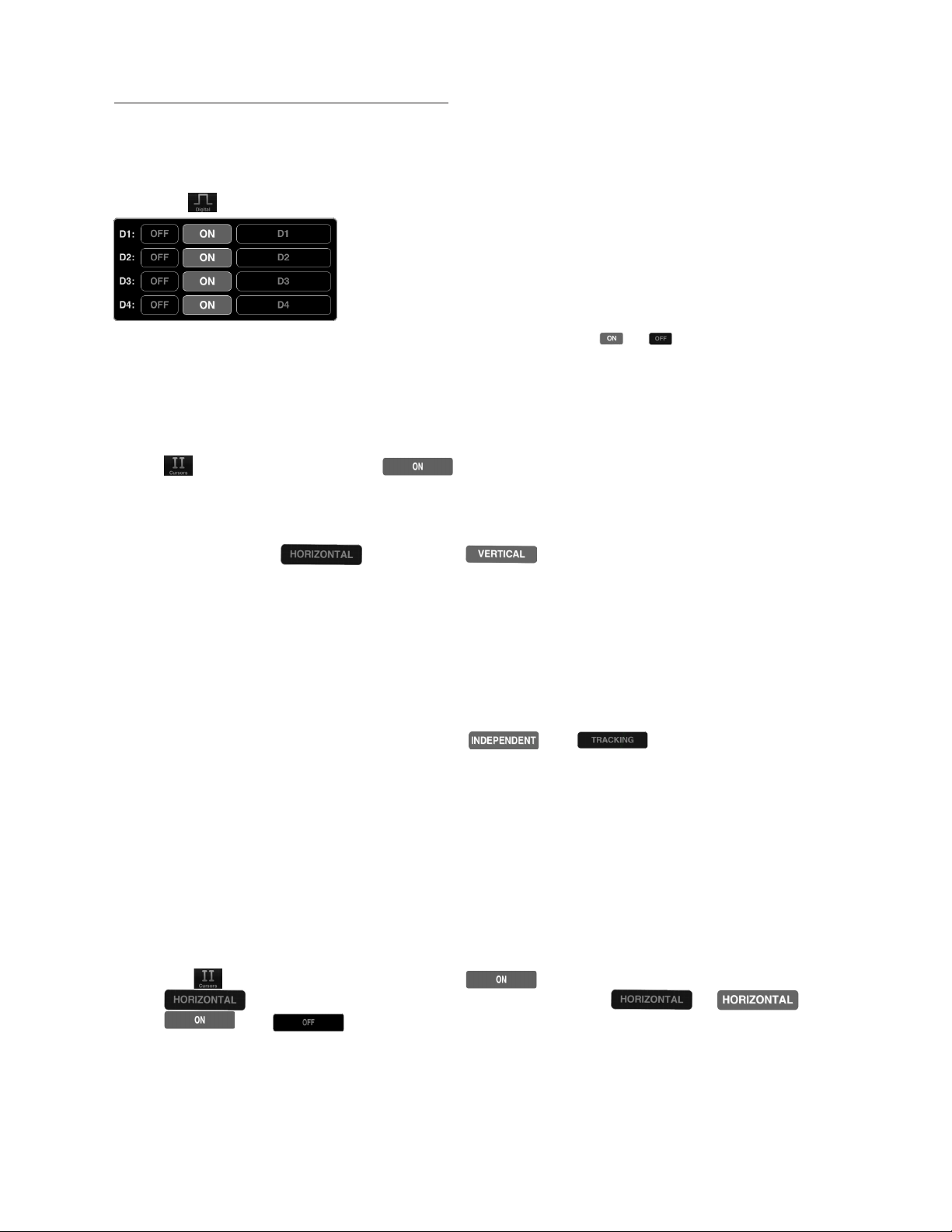
Touch the icon from the menu bar. Tap to activate cursors. Touch from
the cursors menu. On the main screen, touch and swipe the desired cursor in the horizontal
direction and place where desired. The selected cursor will be displayed as a solid line and the
un-selected cursor, a dashed line. The position of the selected cursor is indicated next to @t in
the summary bar. The distance between the two cursors is indicated next to ∆t in the summary
bar. The voltage level at the point where the selected cursor crosses the waveform is indicated
in the summary bar next to @V and the vertical difference between the crossing points of the
two vertical cursors is indicated in the summary bar next to ∆V. When using vertical cursors
with the analog channel both @t, t and @V, V will be visible in the summary bar.
Verify that cursors are selected. To move cursors independently of one another,
touch .To move cursors as a single unit with a fixed distance between them, touch
. The following options are available: .
1.If cursor data is to be displayed in Base, touch .The options next to the word UNIT set
the unit of time.
Time settings available in the Base option include: . The option sets the unit of
measure in seconds. The option sets the unit of measure in hertz.
2. If cursor metrics are to be displayed in Phase, touch . The options next to the phrase
360° WITHIN sets the phase. The option of sets 360° within 5 divisions. The option
sets 360° between the two cursors.
3. If cursor data is to be displayed as a ratio, touch . The options next to the phrase 100%
WITHIN set the ratio. Ratio settings available next to 100% WITHIN include: . The
option of sets 100% within 5 divisions. Since there are 10 divisions in the horizontal time
scale, this option effectively cuts the screen in half. The option sets 100% between the two
cursors.
2.46 FFT Units
Touch the icon from the menu bar. The options next to the phrase FFT Units will set the
voltage units. Voltage options available in the FFT Units option include and . By
touching the option the voltage units will display as volts in the summary bar. Touching the
option will change the voltage units to dBv.
2.50 Measurements
Touch from the menu bar. Fifteen different measurements exist: Min, Max, Mean, Peak to
Peak, RMS, Duty Cycle (+), Duty Cycle (-), Pulse Width (+), Pulse Width (-), Cycle Mean, Cycle
RMS, Frequency, Period, Rise Time, and Fall Time. To scroll through the measurement options,
touch . Then, scroll through the pick wheel to choose the desired measurements. To
activate the settings touch away from the menu.

Revised April 21, 2014
iPad | iPad mini | iPhone | iPod touch
11
Up to six measurements can be selected for either CH A or CH B or a combination of both. Once
selected, measurements appear on the top right of the interface.
2.60 Trigger
2.61 Analog Triggering
The trigger level is controlled with the bubble located on the far right of the screen. If the
bubble is green the triggered signal is CH A. If the bubble is blue, it is triggering on
CH B. To change the trigger from CH A to CH B, touch .Then touch . Then simply
select the SOURCE to be triggered.
To change the voltage level, simply touch and drag the bubble either up or down. Moving the
level up will increase the voltage level and moving it down will decrease the voltage level. The
exact voltage level will appear just to the left of the bubble along with either an up arrow or a
down arrow. An up arrow indicates that the trigger is on a rising edge; a down arrow indicates
that the trigger is on a falling edge. It is also possible to change the trigger level in the
advanced triggering menu. Tap .Then tap and, when active, it will change to .
To navigate to an exact trigger level touch on next to the word LEVEL. The analog
trigger level pick wheel should then appear.
To select the desired trigger level touch and drag in each of the four columns until the specific
value is reached. To activate the settings touch away from the menu. When analog triggering
has been enabled, then all the advanced options for digital triggering will be grayed out.

iMSO-204 & iMSO-204L Manual
iPad | iPad mini | iPhone | iPod touch
Revised April 21, 2014
12
To reactivate the analog trigger, touch . If the analog triggering is grayed out, it is disabled.
Then touch any of the options on the picture below and it will no longer be grayed out.
Analog triggering is always available in demo mode; it is not possible to deactivate until
hardware is used.
To trigger off of a rising edge, touch . If rising is already activated it will look like ,
this means that falling is deactivated, because both falling and rising cannot be active at the
same time. If it is deactivated it will look like , and falling is activated. Touch it once and
it will activate to . To trigger off a falling edge the same procedure should be followed.
Falling should look like when activated and when deactivated.
To recenter your trigger level, touch and your signal will be brought in line
with CH A.
2.62 Digital Triggering
This feature is only available with hardware; it is not available in demo mode. When in demo
mode all the digital triggering options are grayed out.
1. Touch from the menu bar. Then touch at the top of the menu to view more
advanced digital triggering options. All the options may be grayed out (because analog and
digital triggering can’t both be active at the same time). If analog is grayed out, digital is active
and vice versa. To activate the desired trigger, touch one of the advanced triggering options.

Revised April 21, 2014
iPad | iPad mini | iPhone | iPod touch
13
Then, the option that is touched will activate. From the menu, select the desired triggering
function from these options: single channel only , simultaneous events on two channels
, a single event on one of two channels , or concurrent events on two channels .
2. Below the selected triggering functions touch or to select the digital channel from D1
to D4 to be used as channels A and B, respectively.
3. After locating the desired digital channel, touch and when activated, it will change to
. In the previous example, channel A is now D4. Now, the bubble that appears on the far
left of D4 will have an A inside . The A indicates that D4 is now A. Repeat the same process
for B, when applicable.
4. To choose whether triggering occurs on a rising or falling edge, either select for a falling
edge or select for a rising edge.
2.63 Auto vs Normal
Touch . Then touch . Touch the desired mode, either AUTO or NORMAL. For example,
if activating AUTO mode touch and it will change to . Repeat the process for
NORMAL mode. The default setting is AUTO.
2.64 Delay
To set the trigger delay from the main screen, touch the screen and swipe horizontally
to move the trigger point. The bottom portion will detach from the top to set the trigger
position.
To set the trigger delay from the trigger menu, touch then select and press
located next to DELAY. A pick wheel will appear that allows you to set the delay time to the value
shown in the readout.
To select the desired trigger delay touch and drag in each of the four columns until the
specific value is reached. To activate the settings tap away from the menu or tap .
2.65 Holdo
Touch in the menu bar to enter the trigger menu.
Touch . Touch next to HOLDOFF to set the holdoff time. Setting the Holdoff
value should be done in the same manner as the delay.

iMSO-204 & iMSO-204L Manual
iPad | iPad mini | iPhone | iPod touch
Revised April 21, 2014
14
2.66 Analog vs Digital
Touch . Then touch . Touch the desired mode, either ANALOG or DIGITAL. For example,
if activating ANALOG mode touch ANALOG and it will change to . Repeat the process for
DIGITAL mode. The default setting is ANALOG.
2.66 Single-Shot Waveform Capture
If the signal is active, the screen can be paused by touching . Pause is located in the menu
bar, on the far right side. If the signal is paused, the screen will resume real time measurements
by touching . In order to capture a single-shot wave form touch and hold or until
it changes to . Then touch , it will then capture a single-shot waveform. Remember
that in order to trigger off a specific event make sure that the setting is normal. If it is
set to auto you will just get the next frame, not the next event.
2.70 Pinch-to-Zoom
Zooming into a waveform is as easy as zooming into a picture on your smartphone. Our
newest software iMSO2 provides instant feedback showing both the scale you’re in & where
you’re headed.
Current Scale Proposed Scale
The blue number in the top left corner shows your volts per division and the white number in
the top right corner shows the timescale. Focus on the right image. The two solid dots show
where you’re headed and the white outlined dot shows your current scale.
2.80 Demo
2.81 Demo Functions
When no hardware is attached, iMSO2 will operate in Demo Mode. Demo Mode is illustrated
in the bottom right corner by . When hardware is attached, Demo Mode is not available;
iMSO2 will now be in Active Mode. Active Mode is illustrated in the bottom right corner by
. While in Demo Mode, touch to change the function that is being viewed. Although
four different wave forms can be viewed on each analog channel, only one waveform can
be viewed on each channel at any given time. To change the wave form being viewed, touch
then pick the desired waveform in the pick wheel. To activate the setting touch
away from the menu.

Revised April 21, 2014
iPad | iPad mini | iPhone | iPod touch
15
2.82 Demo Amplitude
Touch from the menu bar on the right. To change the of the signal touch
located to the right of . Enter the desired voltage using the pick wheel. To activate the
setting tap away from the menu.
2.83 Demo Frequency
Touch from the menu bar on the right. To change the of the signal, touch
located to the right of . The pick wheel pops up and it is now possible to modify the
frequency by selecting the desired frequency. Frequencies can be entered in Hz, kHz, or MHz.
To activate the settings tap away from the menu.
2.84 Demo DC Oset
Touch from the menu bar. To set the DC offset, touch located to the right of
. Then select the desired voltage offset from the pick wheel. To activate the settings tap away
from the menu.
2.85 Duty Cycle
In order to change the Duty Cycle, the demo mode must be set to . Once the
demo mode is switched to square the Duty Cycle option will change from to
. To change the of the signal, touch . Enter the desired voltage
using the pick wheel. To activate the setting tap away from the menu or tap .
2.90 Settings
iPhone/iPod touch- When hardware is connected, disappears and is replaced by
Then all additional setting are unlocked. In order to change the settings while in demo mode,
touch and hold until it changes to .
iPad/iPad mini- appears in the main menu bar. When hardware is connected
disappears. Then all additional settings are unlocked.
2.91 Grid Settings

iMSO-204 & iMSO-204L Manual
iPad | iPad mini | iPhone | iPod touch
Revised April 21, 2014
16
Lines vs. Dots
Touch . Then touch the desired selection, either or . This setting
affects the way that the signals are displayed; it will either be point by point (dots) or it will be
represented with a line.
Graticule
Touch . Then touch or to scroll through the various background display options. They
include: Crosshairs, Major Tics, Minor Tics, Major Grid, Minor Grid, and finally Graticule. Once a
selection is tapped it becomes active and changes from to . Touching
graticule is a shortcut for tapping all of the above.
2.92 Alerts
Touch . Three alerts are available. They are located on the third row from the top: ALERTS,
ON STARTUP & ON DISCONNECT. Cycle through the options by tapping or next to the
selection. Then tap the selection to activate it. To deactivate a specific alert, touch the alert
and it will change from to . Touching is a shortcut for tapping all
of the above.
2.93 Persistence
Touch . Then touch and swipe the dot to the right of persist .For the
advanced options relating to , touch . Digital persistence can either be turned off or
on. To turn it on, tap . To turn digital persistence off, touch .
2.94 Sounds
Sounds can be controlled either through hardware or software. The Apple device can control
the sound (in the same way it always controls sound) by using the plus/minus volume controls
on the side of the device. In the software, sounds are turned off by tapping . Then touch
SOUNDS and it will either turn sounds on or off .
2.95 Compensation
The iMSO-204 and iMSO-204L is shipped fully calibrated and fully compensated. If, for any
reason, the analog input ever needs to be re-compensated, iMSO-204L (and iMSO-204) both
have built-in 3.3 V, 1 kHz reference signals. Regardless of whether the function generator we
provide is used or if an external input is used, the electrically isolated flathead screwdriver will
help trim the signal. Here’s how to use the built-in reference wave:
Touch from the menu bar. From the setting menu, tap to enable the 3.3 V calibration
signal. When the signal is activated changes to . Next, select on the menu
bar and ensure is selected. Insure the switch on the analog probe is switched to 1x.
Connect the SMD grabber for GND (or the black wire) to the ground clip for the analog probe.

Revised April 21, 2014
iPad | iPad mini | iPhone | iPod touch
17
Remove the connector attachment from the analog probe. Then connect the SMD grabber for D1
(or the purple wire) to the tip of the analog probe.
2.96 Screenshot
Two options exist. First, a screenshot can be captured by simultaneously pressing both the
home button and the power button on your Apple device. The screen will flash white while the
picture is captured. When a picture is captured this way, everything visible on the LCD will be
captured and available in photos. The second option is to touch and then touch. The text
SCREENSHOT will fade to from black to gray and the display will briefly change to full screen
mode. Although this is a very useful method, it may not always be the best way to take a
screenshot. By simultaneously pressing the home and the power button, it is possible to take a
picture of exactly what is on the screen. In some cases, this will be the best option.
2.97 Email
Touch . Then, touch . The email will consist of the image currently displayed on
the screen. Although it is not possible to retrieve screenshots from this spot, the pictures are
still available in photos where they can be emailed. The other option is to simultaneously press
both the home button and the power button on your Apple device. The screen will flash white
while the picture is captured. When a picture is captured this way, everything visible on the
screen will be captured and available in photos where they can be emailed.
2.98 Manage Data Log
This feature is only available with hardware; it is not available in demo mode. When in demo
mode the data logging options for DATA LOG: START and STOP are grayed out.
Touch from the menu bar. Then touch from the data log option, .
will then change to in order to indicate data is being logged. To stop data logging tap
.
Touch . Then touch . A pick wheel will appear with all of the data that has
been previously logged. To select precious data log tap away from the menu.

iMSO-204 & iMSO-204L Manual
iPad | iPad mini | iPhone | iPod touch
Revised April 21, 2014
18
When viewing the .csv data file:
Each column (excluding the first) is the data point in time that is shown on the screen.
When the time scale is set to less than 100ms, each row is a single screen capture.
When the time scale is greater than or equal to 100ms, each row is a data point in time.
2.99 Configuration Settings
Reset Configurations
To reset the configuration, touch . Then touch .
Saving Configurations
Up to three configurations can be saved at a time. Touch . Then touch next
to CONFIG 1, 2 or 3. will turn to and then back to , indicating the
configuration has been successfully saved.
To upload a saved configuration touch . Will turn to and then back
to , indicating the configuration has successfully been loaded.

19
Revised April 21, 2014
Section 3 – Product Warranty & Accessories
3.10 Product Warranty
iMSO-204 & iMSO-204L hardware both come with a full one year manufacturer’s warranty.
No warranty exists on probes and accessories.
3.20 Accessories
iMSO-204 and iMSO-204L come with the following accessories: 1x / 10x analog probe, logic
harness, five SMD grabbers, and one screwdriver.
3.21 1x / 10x Analog Probes
The analog probe is capable of measuring signals up to 100 MHz (although our fastest
scope is currently limited to 50 MSPS). This probe can operate in either 1x or 10x mode. It is
removable with an SMB connector.
3.22 Logic Harness
The logic harness is has five colors: purple (D1), yellow (D2), blue (D3), orange (D4), and black
(ground). The colors on the harness match up with the colors on the interface. If a user is
color blind, the harness colors are labeled D1, D2, D3, D4, and GND on the back of the iMSO-
204/iMSO-204L hardware
3.23 SMD Grabbers
SMD grabbers have the Oscium flame custom built into the front.
3.24 Screwdrivers
The electrically-isolated flathead screwdriver is custom made for iMSO-204 and iMSO-204L
and is used for compensating the device.

iMSO-204 & iMSO-204L Manual
Revised April 21, 2014
20
Section 4 – Performance Specifications
iMSO-204 & iMSO-204L
Display
9.7” (iPad 4th gen, 3rd gen, iPad 2, iPad)
7.9” iPad Mini
3.5” (iPod touch 5th gen, 4th gen,
iPhone 5S, iPhone 5C, iPhone 5
iPhone 4s, iPhone 4, iPhone 3GS)
Resolution 2048x1536 (iPad 3rd gen), 1024x768 (iPad 2, iPad), 960x640
(iPod touch 4th gen/iPhone 4S, iPhone 4), 320x480 (iPhone 3GS)
Analog 2 Channel, 8 bit
Analog Probe 1x & 10x selectable, removable with SMB
Digital 4
Digital Probe 4 bits, 1 Gnd, 0.100” connectors with removable SMD Grabbers
Analog Bandwidth 5MHz
Max Sample Rate 50MSPS
Sample Depth 1000pts
Horizontal Sensitivity 200ns/div-10s/div
Horizontal Position Adjustable
Trigger Position Adjustable
Vertical Sensitivity 50mV/div to 2v/div (1x); 500mV/div to 20v/div (10x)
Vertical Position Adjustable
Max Digital Input Voltage -0.5v to +7v
Max Input Voltage -8v to +13v (1x); -40v to +40v (10x)
Coupling AC of DC
Trigger Modes Auto/Normal/Single/Stop
Trigger Types Analog, Digital (A, A&B, A|B, A B)
Live Measurements 6
Measurement Types Frequency
Period
Min
Max
Mean
Peak to Peak
RMS
Positive Duty Cycle
Negative Duty Cycle
Positive Pulse Width
Negative Pulse Width
Cycle Mean
Cycle RMS
Rise Time
Fall Time
Features Screen Capture Email
Demo mode (Analog)
Horizontal/Vertical Cursor Measurements
Reference Capture
Delay (always on) / Holdo ~99.99s max
FFT, Data Logging, Advanced Math
This manual suits for next models
1
Table of contents
Other Oscium Measuring Instrument manuals