OSD NETWORKS OSD2524P User manual

OSD2524P
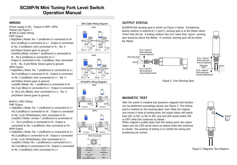
Layer Managed 26-port Ethernet Switch
With 4 x Combo & 2 x Gb SFP Ports
With IEEE802.3bt PoE
Quick Start Guide


PAGE 3 10120901
OSD2524P Quick Start Guide
INDEX 1
1TECHNICAL SUMMARY ................................................................................................4
1.1 BRIEF DESCRIPTION.................................................................................................4
1.1.1 OVERVIEW ...........................................................................................................................4
1.1.2 FEATURES AND BENEFITS ................................................................................................4
1.2 TYPICAL SYSTEM DESIGN........................................................................................5
1.3 TECHNICAL SPECIFICATIONS..................................................................................5
1.4 PORT ALLOCATION....................................................................................................8
2INSTALLATION AND OPERATION...............................................................................9
2.1 INTRODUCTION..........................................................................................................9
2.2 INSTALLATION............................................................................................................9
2.2.1 WARNING AND PRECAUTIONS..........................................................................................9
2.2.2 DRAWINGS AND DIMENSIONS.........................................................................................10
2.2.3 LOCATION ..........................................................................................................................11
2.2.4 POWER SUPPLY CONNECTIONS.....................................................................................11
2.2.5 USB CONNECTOR.............................................................................................................12
2.2.6 LED INDICATORS...............................................................................................................13
2.2.7 FITTING SFP CONNECTORS ............................................................................................15
2.3 OPERATION..............................................................................................................16
2.3.1 CONNECTIONS..................................................................................................................16
2.4 COMMAND LINE INTERFACE..................................................................................17
2.4.1 CLI COMMANDS (TOP LEVEL)..........................................................................................18
2.4.2 RESET CONFIGURATION TO FACTORY DEFAULT ........................................................19
2.4.3 SET HOSTNAME AND ADMIN USER PASSWORD...........................................................19
2.4.4 SET VLAN 1 IP ADDRESS..................................................................................................20
2.4.5 SAVE CONFIGURATION TO FLASH..................................................................................20
3WEB GUI.......................................................................................................................21
3.1.1 DEFAULT SETTING............................................................................................................21
3.1.2 LOG INTO THE SWITCH ....................................................................................................21
3.1.3 IP CONFIGURATION..........................................................................................................22
3.1.4 USERS AUTHENTICATION................................................................................................23
3.1.5 SAVE CONFIGURATION TO START-UP...........................................................................24
3.1.6 CONFIGURE POE...............................................................................................................24
4MAINTENANCE ............................................................................................................25
4.1 INTRODUCTION........................................................................................................25
4.2 EXTERNAL INSPECTION .........................................................................................25
4.3 ROUTINE MAINTENANCE........................................................................................25
5WARRANTY..................................................................................................................26
5.1 WARRANTY PERIOD................................................................................................26
5.2 REPAIRS ...................................................................................................................26
5.2.1 WARRANTY REPAIRS .......................................................................................................26
5.2.2 OUT-OF-WARRANTY REPAIRS.........................................................................................26
5.2.3 SITE REPAIRS....................................................................................................................26
5.2.4 EXCLUSIONS .....................................................................................................................26
FIGURE 1: TYPICAL SYSTEM DESIGN ..........................................................................................5
FIGURE 2: FRONT/REAR PANEL....................................................................................................8
FIGURE 3: MOUNTING DIMENSIONS...........................................................................................10
FIGURE 4: POWER SUPPLY CONNECTIONS..............................................................................11
FIGURE 5: USB TYPE B CLI PORT ...............................................................................................12
FIGURE 6: CLI INSTALLATION......................................................................................................12
FIGURE 7: PORT/LED....................................................................................................................13
FIGURE 8: FITTING/REMOVING SFP CONNECTORS.................................................................15
TABLE 1: TECHNICAL SPECIFICATIONS.......................................................................................6
TABLE 2: POWER CONNECTION .................................................................................................11
TABLE 3: LED FUNCTION..............................................................................................................14

PAGE 4 10120901
OSD2524P Quick Start Guide
1 TECHNICAL SUMMARY
1.1 BRIEF DESCRIPTION
1.1.1 OVERVIEW
The OSD2524P is a Layer 2 managed 26-port industrial ethernet switch offering Power over Ethernet
meeting the latest IEEE802.3bt PoE specification with continued support for devices requiring
IEEE802.3af/at. Eight RJ45 are each capable of supplying up to 90W of power to support the latest PoE
devices with a total power budget of 720W. All 24 RJ45 ports can support up to 30W per port concurrently.
For increased flexibility there are four RJ45/SFP combo ports along with two Gigabit SFP uplink ports
which can be used as standard ports or as an ITU-TG 8032 redundant ring. With support for VLAN, IGMP
snooping, industry standard RSTP or MSTP and IEEE802.1x port security, it is suitable for use in critical
networks. A rugged, fan-less 1RU high, IP30 19”rack mounting enclosure and an operating temperature
range from -20 to +70ºC make it suitable for use in a wide range of harsh industrial environments.
1.1.2 FEATURES AND BENEFITS
▲Security
With increasing demand for security on distribution and edge switches, the
OSD2524P supports 802.1x Port based and MAC based access authentication.
Private connections are guaranteed with SSH, Radius and TACACS+ options whilst
the latest SNMPv3 protocol is supported.
▲Redundancy
To guarantee performance in critical applications, the OSD2524P comes with a dual
redundant DC power input. In case of a break in the fiber network the OSD2524P
supports ITU-TG 8032 Ethernet Ring Protection Switching to ensure the system
reliability. Loop protection is prevented by MSTP/RSTP/STP protocols.
▲Management
The OSD2524P supports industry standard SNMP v1, v2c and V3 for use with third
party NMS. Standard MIB’s and OSD private MIBs provide a wide range of
parameters that can be monitored or configured remotely. Each OSD2524P has a
built in Web browser GUI where detailed information about the individual unit can be
accessed and configuration, settings and logs can be viewed and changed. SNMP
traps can be set to alert the user in case of some faults such as a problem with the
network or a connected device failure.
▲IEEE802.3bt Compliant
With an overall PoE power budget of 720W the OSD2524P can be deployed in a wide
range of communication networks. 8 ports are IEEE802.3bt compliant with each
providing up to 90W per port to support the latest IP PTZ cameras, Wireless Access
Points, Thin Clients, PoE lighting and other powered devices.

PAGE 6 10119802
OSD2524P Quick Start Guide
TABLE 1: TECHNICAL SPECIFICATIONS
Hardware
Ethernet
24 x 10/100/1000Base-T RJ45, IEEE802.3i/802.3u/802.3ab
Data Rate
10, 100, 1000Mbps with energy detect, auto negotiate, auto
MDIX
Jumbo Frame Support
9.6KB
SFP
4 x SFP Combo ports, 2 x Gigabit SFP trunk ports
Optical Data Interface
IEEE802.3z 1000Base-Lx/Sx
PoE (user configurable via GUI)
IEEE802.3af/at, IEEE802.3bt (Ports1-8), Legacy PoE (DC
capacitance)
CPU Memory
128Mb
Switching Speed
27Gbps switching backplane
Enclosure Protection Class
IP30
Installation
Desktop or 19”rack mount
Mode Selection Switch (push)
Link/Speed, Link/Duplex, Link/Status, PoE status
Reset Button (recessed push)
Reset unit
Power Requirements
48 to 57VDC @ 40VA maximum (no PoE in use) to 800VA
maximum (PoE of 720W)
≥52VDC recommended for PD meeting IEEE802.3at &
IEEE802.3bt
≥55VDC recommended for total PoE power requirement >600W
Output PoE Vdrop per port
PoE voltage drop per port <0.5V @ 30W, <1V @ 60W
Power Connector
8 way 5.08mm terminal block for dual redundant DC powering
Indicators
24 x Mode selectable LEDs (amber/green) for RJ45 ports
6 x Speed/Activity/Link LEDs on each SFP
1 x Status
2 x Power (rear panel)
Environmental
-20 to +70ºC
Relative Humidity
0 to 95% non-condensing
Dimensions
440W x 295D x 44H mm (desktop mount)
Weight
5400g
Management
Interfaces
Command Line Interface (CLI mini USB)
Web browser based Graphical User Interface (GUI)
SNMP v1, v2c, v3
Port Status
Speed, duplex mode, link status, auto negotiation status
PoE Status
GUI controlled for each individual port
Managements
Configuration download or upload.
Dot3-OAM-MIB
RFC 1213 MIB
LLDP-MED power MIB
Bridge MIB
MSTP MIB
LLDP MIB
Private MIB Framework
Contact OSD for full list of MIBs

PAGE 7 10119802
OSD2524P Quick Start Guide
Layer 2 / Layer 3
Port Configuration
Port enable/disable, Auto negotiation, Flow control
enable/disable
Port Status
Speed, duplex mode, link status, auto negotiation status
VLAN
802.1Q VLAN.
Private VLAN, Voice VLAN
Protocol based VLAN
GVRP, MVRP, MRP
QoS
Traffic Classes, Port policers, Port egress shaper, QoS Control
List, DiffServ, Scheduler
priority, Storm Control
Multicast Protocol
RFC 2236 IGMP snooping v2, v3
MLD snooping v1, v2
IPv4/IPv6
IPv4 and IPv6 dual stack for data & management
DHCPv6 relay, DHCPv6 client. NTP
Security
ACLs, DHCP snooping, BPDU Guard
RADIUS, TACACS+, SSL, SSH, HTTPS, SSLv3, Port Mirroring,
sflow,
Dynamic ARP Inspection, IP source guard, UDLD/equivalent,
RMON
IEEE802.1x Port Access Authentication, MAC based
authentication
Ethernet Redundancy
IEEE802.1D Spanning Tree Protocol
IEEE802.1w Rapid Spanning Tree Protocol
IEEE802.1s Multiple Spanning Tree Protocol
ITU-TG.8032 Ethernet Ring Protection
Link Aggregation
Static and LACP link aggregation
Universal plug and Play
UPnP
L3 Routing
IPv4/IPv6 static routing
PoE Options
Ports 1-8
Disable, Standard mode (802.3bt, 802.3af/at), Legacy support
Ports 9-24
Disable, Standard mode (802.3af/at), Legacy support
Environmental
Operating Temperature
-20 to +70ºC
Relative Humidity
5 to 95% non-condensing
Warranty
Warranty Period
5 years
MTBF (Ground Benign Environment,
30ºC)
160,000 hours (360W power consumption @ 30ºC)

PAGE 8 10119802
OSD2524P Quick Start Guide
1.4 PORT ALLOCATION
Front Panel: There are 24 fixed copper ports: 8 x IEEE802.3bt, 16 x IEEE802.3af/at, 4 x
RJ45/SFP combo ports and two Gigabit SFP uplink trunk ports. There is also a CLI Console
port (mini USB)
Rear Panel: 8-Way 5.08mm terminal block for dual redundant DC powering.
Each section will be described further throughout this manual.
FIGURE 2: FRONT/REAR PANEL
Front Panel
Rear Panel
Dual
Redundant DC
Power
Earth Screw
Power LED x 2
Function
LED x 4
Status
LED
Reset
Push
Button
PoE
IEEE802.3bt
RJ45 x 8
Trunk Port
2 x SFP
Combo Port
4 x RJ45
4 x SFP
Mode
LEDs x 24
View
Push
Button
Console
Port
PoE
IEEE802.3af/at
RJ45 x 16

PAGE 9 10119802
OSD2524P Quick Start Guide
2 INSTALLATION AND OPERATION
2.1 INTRODUCTION
This section outlines the methods required to install and operate the OSD2524P successfully.
It should be studied carefully if damage to the equipment or poor results are to be avoided.
This equipment has been fully tested prior to dispatch and is ready for immediate operation.
However, it is advisable to check for external transportation damage before operation. If
damage is evident, return the unit with the packaging to your supplier immediately.
2.2 INSTALLATION
2.2.1 WARNING AND PRECAUTIONS
▲ELECTROMAGNETIC COMPATIBILITY
WARNING: This is a Class A product. In a domestic environment this product may cause
radio interference in which case the user may be required to take adequate measures.
▲OPTICAL OUTPUT OPERATION
WARNING: Laser Safety: Class 1 Laser Product per IEC/EN 60825-1:2014 standard.
Class 1
The OSD2524P is a Class 1 laser product.
PRECAUTIONS
▲All service personnel should be provided training as to the hazards of direct viewing
of laser radiation and of the precautionary measures during servicing of equipment
▲Areas where laser products are installed should be restricted in access to trained
service personnel only and appropriate warning signs posted in the work area.
▲All laser apertures should be covered by protective covers when not connected to
optical fibers. Never leave outputs uncovered.
▲Laser equipment should be positioned above or below eye level where possible.
Apertures should be positioned away from personnel.
▲Protective eyewear should be worn in the vicinity of laser equipment.

PAGE 11 10119802
OSD2524P Quick Start Guide
2.2.3 LOCATION
As with any electrical device, the OSD2524P should be placed where the switch will not be
subjected to extreme temperatures, humidity, or electromagnetic interference. Specifically,
the site selected should meet the following requirements:
•The ambient temperature should be between -20°C to 70°C.
•The relative humidity should be less than 95 percent, non-condensing.
•Surrounding electrical devices should not exceed the electromagnetic field (RFC)
standards.
•Make sure that the switch receives adequate ventilation. Do not block the ventilation
holes on any side of the switch.
Note: Without proper cooling and control (lowering) of ambient temperature, the components
within the OSD2524P can be subject to increased heat shortening the longevity and reliability.
It is thus good engineering practice to ensure the unit is installed in a well ventilated area.
2.2.4 POWER SUPPLY CONNECTIONS
The OSD2524P requires external power to the Redundant DC Terminal Block Power
Connector located at the rear of the unit. Always ensure that the power is off before any
installation.
Redundant DC Terminal Block Power Inputs
There are two pairs of power inputs for use with redundant power sources. Only one power
input is required to be connected to run the switch.
Step 1: Connect the DC power to the appropriate power source, connect the plug-able
terminal block on the OSD2524P switch and then turn power on.
Step 2: Disconnect the power if you want to shut down the switch.
TABLE 2: POWER CONNECTION
External Power Pin
Specification
Power 1 +
48VDC to 57VDC*
Power 1 0V
Ground –0V
Power 2 +
48VDC to 57VDC*
Power 2 0V
Ground –0V
Earth Ground Connection
*48 to 57VDC @ 40VA maximum (no PoE in use) to 800VA maximum (PoE of 720W)
≥52VDC recommended for PD meeting IEEE802.3at & IEEE802.3bt
≥55VDC recommended for total PoE power requirement >600W
FIGURE 4: POWER SUPPLY CONNECTIONS

PAGE 12 10119802
OSD2524P Quick Start Guide
2.2.5 USB CONNECTOR
The OSD2524P has a mini USB connector located on the front of the unit that is used for
Command Line Interface (CLI) from the PC to the OSD2524P via the PC’s USB connector.
See section 2.4 for further CLI information.
FIGURE 5: USB TYPE B CLI PORT
To operate and control the OSD2524P using the CLI, a proprietary driver will be required to
be installed onto the PC being used. The driver can be found and downloaded via the
following site: www.silabs.com and searching for the CP210x driver. Download the relevant
driver for your operating system, install and follow the installation instructions from your PC.
FIGURE 6: CLI INSTALLATION
Mini USB - CLI Port

PAGE 13 10119802
OSD2524P Quick Start Guide
2.2.6 LED INDICATORS
*The View Push Button when pressed will cycle through Link/Speed, Link/Duplex, Link/Status,
PoE. This will indicate the Port LED (1-24) function.
FIGURE 7: PORT/LED
View Push
Button*
Display
Function
LED Port
Indicators
SFP Combo Port
LED x 4
SFP Trunk Port
LED x 2
Power 1 LED
Power 2 LED

PAGE 14 10119802
OSD2524P Quick Start Guide
TABLE 3: LED FUNCTION
LED
Function
Board Status
Green
Normal Operation
Red (Blink)
Internal Warning
Display Function
The View Push Button when pressed will
cycle through Link/Speed, Link/Duplex,
Link/Status, PoE. This will indicate the Port
LED (1-24) function
Port Indicators (x 24) –Link/Speed Mode
Green
1Gbps
Amber
10/100Mbps
Off
No Connection
Blinking
Traffic
Port Indicators (x 24) –Link/Duplex Mode
Green
Full Duplex
Amber
Half Duplex
Off
No Connection
Blinking
Traffic
Port Indicators (x 24) –Link/Status Mode
Green
Connection Established
Off
No Connection
Port Indicators (x 24) –PoE Mode
Green
Dual Signature PD
Amber
Single Signature PD
Off
No PoE Detected
Trunk Port
Green
1Gbps
Amber
100Mbps
Off
No Connection
Power 1 / Power 2
Green
Power Connected
Off
No Power connected
Note: Ports 21-24 are Combo ports, Either the fixed RJ45 port or the SFP ports are
operational at one time.

PAGE 15 10119802
OSD2524P Quick Start Guide
2.2.7 FITTING SFP CONNECTORS
Care should be taken when inserting/removing the SFP connectors from SFP port 9 and 10
as SFP modules are Electrostatic (ES) sensitive and Electrostatic Discharge (ESD)
precautions should be taken when installing. Ensure that the SFP is fully engaged and
latched into position.
Inserting SFP –Ensure that the SFP lever is in the locked position and insert into appropriate
SFP port. Gently push the SFP until it locks into place. Remove plastic/rubber dust cap and fit
fiber cable or RJ45 plug.
Removing SFP –Remove fiber connector or RJ45 plug. Pull the SFP lever down to unlock
SFP from housing. Using the lever, gently pull the SFP out.
Fiber SFP
Copper SFP
FIGURE 8: FITTING/REMOVING SFP CONNECTORS
Inserting
SFP
Removing
SFP
1
2
Inserting
SFP
Removing
SFP
1
2

PAGE 16 10119802
OSD2524P Quick Start Guide
2.3 OPERATION
When using the OSD2524P for the first time, check that the unit is in good condition with no
visible damage.
Upon power up check that the indicators illuminate accordingly on power up (see Table 3).
2.3.1 CONNECTIONS
For RJ45 connection use Category 5 (CAT5) or higher. Length should be no more than 100
meters.
For singlemode fiber connections, fiber used must be 9/125μm singlemode fiber.
For multimode fiber connections, fiber used must be 50/125μm or 62/125μm multimode fiber.
Plug in the appropriate connectors for system configuration;
–RJ45 cable to fixed copper ports and copper SFP modules
–LC or SC fiber cable to fiber SFP modules.

PAGE 17 10119802
OSD2524P Quick Start Guide
2.4 COMMAND LINE INTERFACE
The Command Line Interface (CLI) is a useful tool for checking link status and debugging link
connections. To enable the use of CLI the OSD2524P must be connected to a PC with a
serial port and an appropriate cable as specified in section 2.2.5. Using a terminal emulation
program such as Hyperterminal, a number of command lines specific to the OSD2524P can
be implemented to check link/node status, ring/bus topology and enable/disable float backup.
Note: Screen shots may vary due to terminal emulation programs and minor software
updates. The screen shots are for illustrative purpose only.
1. Connect the Console Port on OSD2524P (Mini USB) to PC with USB cable.
2. Using HyperTerminal, SecureCRT, etc to set up the following parameters.
•Baud Rate: 115200
•Data Bits: 8
•Parity: None
•Stop Bits: 1
•Flow Control: None
3. Check the link by pressing <ENTER>. The line should jump to the next line.
4. Using the Username and password to login the switch
5. If there is no user input for a period of time, the user will be locked out and will require
to re-enter by pressing ENTER.
6. The admin username is operating at the highest priveldge level (level 15) and has full
control over the OSD2524SFP and its configuration. On this level, the admin can
reset the OSD2524SFP configuration to factory default.

PAGE 18 10119802
OSD2524P Quick Start Guide
2.4.1 CLI COMMANDS (TOP LEVEL)
By entering “?” a list of CLI commands available with a brief description will be displayed
Some terminal emulators like SecureCRT support the “Tab” key. At the # prompt pressing the
“Tab” key will also produce a list of available commands within the command level. Partially
typing a command and hitting “Tab” key will autocomplete the command.
Help may be requested at any point in a command by entering a question mark “?”. If there
are no command arguments available, the help list will be empty and the user must backup
(backspace) until entering a “?” shows the available options. There are two types of help
provided;
1. Full help is available when the user is ready to enter a command argument (eg.
“show”) and describes each possible argument.
2. Partial help is provided when an abbreviated argument is entered and user wants to
know what arguments match the input (eg “show pr?”)
Note that there are sub-commands for every 1st level commands eg. # clear ? will display all
sub command arguments associated with the clear command. The CLI will then display #
clear and wait for the sub command.

PAGE 19 10119802
OSD2524P Quick Start Guide
2.4.2 RESET CONFIGURATION TO FACTORY DEFAULT
To reset the configuration to factory defaults;
# reload defaults
When the promt returns, the unit has reverted to factory defaults
2.4.3 SET HOSTNAME AND ADMIN USER PASSWORD
The CLI has several different modes. When entering the CLI through the admin entry, the
mode is in exec mode. This allows the user to modify configuration files, reload defaults,
system information etc. When the unit is in configuration mode, the user can change detailed
configurations.
To set the OSD2524P host name, the unit needs to be first set to configuration mode then
enter the hostname command, then a chosen hostname. After this is entered, the unit
requires an ‘exit’ from configuration mode.
The host name has now changed to “OSD2524P-Sec1” and can be seen on the prompt.
A new password for the ‘admin’ user is recommended to be set.
In the example above the password was changed to “OSD”. Other users can be added using
the above method.

PAGE 20 10119802
OSD2524P Quick Start Guide
2.4.4 SET VLAN 1 IP ADDRESS
To display current IP address and subnet mask details;
# show ip interface brief
To configure a new IP address the unit needs to be first set to configuration mode then enter
the interface VLAN number, then a chosen IP address. An ‘exit’ from configuration mode is
also required when changes are made. Note that the chosen input arguments (IP
address/Subnet mask) are not in bold shown in the example below.
Switch# configure terminal
Switch(config)# interface vlan 1
Switch(config-if-vlan)# ip address 192.168.0.99 255.255.0.0
Switch(config-if-vlan)# end
Note: IP addresses can only be assigned to VLAN interfaces.
After configuration the IP address is completed, the newly allocated IP address can be
checked again by typing in;
# show ip interface brief
If the DHCP negotiation failed, the fallback IP is assigned (192.168.0.99)
2.4.5 SAVE CONFIGURATION TO FLASH
It is necessary to save any changes to FLASH storage in the ‘startup-config’ otherwise the
changes will not take effect when the unit is powered off. To save the changes the
configuration needs to be copied to the startup configuration.
# copy running-config startup-config
Other OSD NETWORKS Switch manuals


