OSF WATERFRIEND MRD-3 User manual

Installation and Operating Instructions
Water treatment system for pH, chlorine and ORP
Technische Daten PN-220 (N)
Technical Data WATERFRIEND exclusiv
Nominal voltage
Metering pump pH-
Metering pump chlorine
Protection class
Housing size
IP 20
625 x 390 x 130
Humidity
Ambient temperature
0 to 40 °C
Metering pump flocculation
(option)
0 bis 10 l / h
1/N/PE 230V/50Hz
Measuring water pressure
max. 2 bar
0 bis 10 l / h
0 to 95%, non
condensing
Metering pump pH+ (option) 0 bis 10 l / h
Measuring water flow rate 0,5 l/min.
Made by
MRD-3

Installation and operating manual for WATERFRIEND -Chlorine MRD-3 Page 2
Subject Table of contents Page
General.............................................................................................................................................................. 5
Safety information ........................................................................................................................................... 5
Installation and operating manual .............................................................................................................. 5
Canister ...................................................................................................................................................... 5
Personnel qualification ............................................................................................................................... 5
Installation........................................................................................................................................................ 6
Mounting..................................................................................................................................................... 6
Installation in the water circuit .................................................................................................................... 6
Schematic................................................................................................................................................... 6
Measurement water pump.......................................................................................................................... 7
General informational installation in the water circuit................................................................................. 7
Electrical connection....................................................................................................................................... 7
Low-voltage cables..................................................................................................................................... 7
Wiring diagram................................................................................................................................................. 8
Alarm .......................................................................................................................................................... 8
External pumps........................................................................................................................................... 8
Enabling...................................................................................................................................................... 8
RS-485........................................................................................................................................................ 8
Connecting to the computer network.......................................................................................................... 8
Using the -communication server......................................................................................................... 9
Read device ID on the display of the dosing control................................................................................ 10
Touchpanel..................................................................................................................................................... 11
Temperature............................................................................................................................................. 11
Measurement water flow quantity............................................................................................................. 11
Display ............................................................................................................................................................ 12
Analog display .......................................................................................................................................... 12
Initial setup..................................................................................................................................................... 13
Select language........................................................................................................................................ 13
Set date and time ..................................................................................................................................... 13
Adjust the flow rate of the measurement water........................................................................................13
Calibrate the sensors................................................................................................................................ 13
Turn on automatic dosing.........................................................................................................................13
Set delivery performance of metering pumps........................................................................................... 13
Operation........................................................................................................................................................ 14
Child lock.................................................................................................................................................. 14
Professional mode (expert level).............................................................................................................. 14
pH regulation.................................................................................................................................................. 15
Switching pH regulation on or off .............................................................................................................15
Setting the pH target value....................................................................................................................... 15
Setting the lower pH alarm....................................................................................................................... 16
Setting the upper pH alarm....................................................................................................................... 16
Calibrating the pH electrode..................................................................................................................... 16
Calibrating the upper value (pH 7) ........................................................................................................... 17
Calibrating the lower value (pH 4)............................................................................................................17
pH calibration errors ................................................................................................................................. 17
pH power on delay.................................................................................................................................... 18

Installation and operating manual for WATERFRIEND -Chlorine MRD-3 Page 3
Setting the maximum pH metering time....................................................................................................18
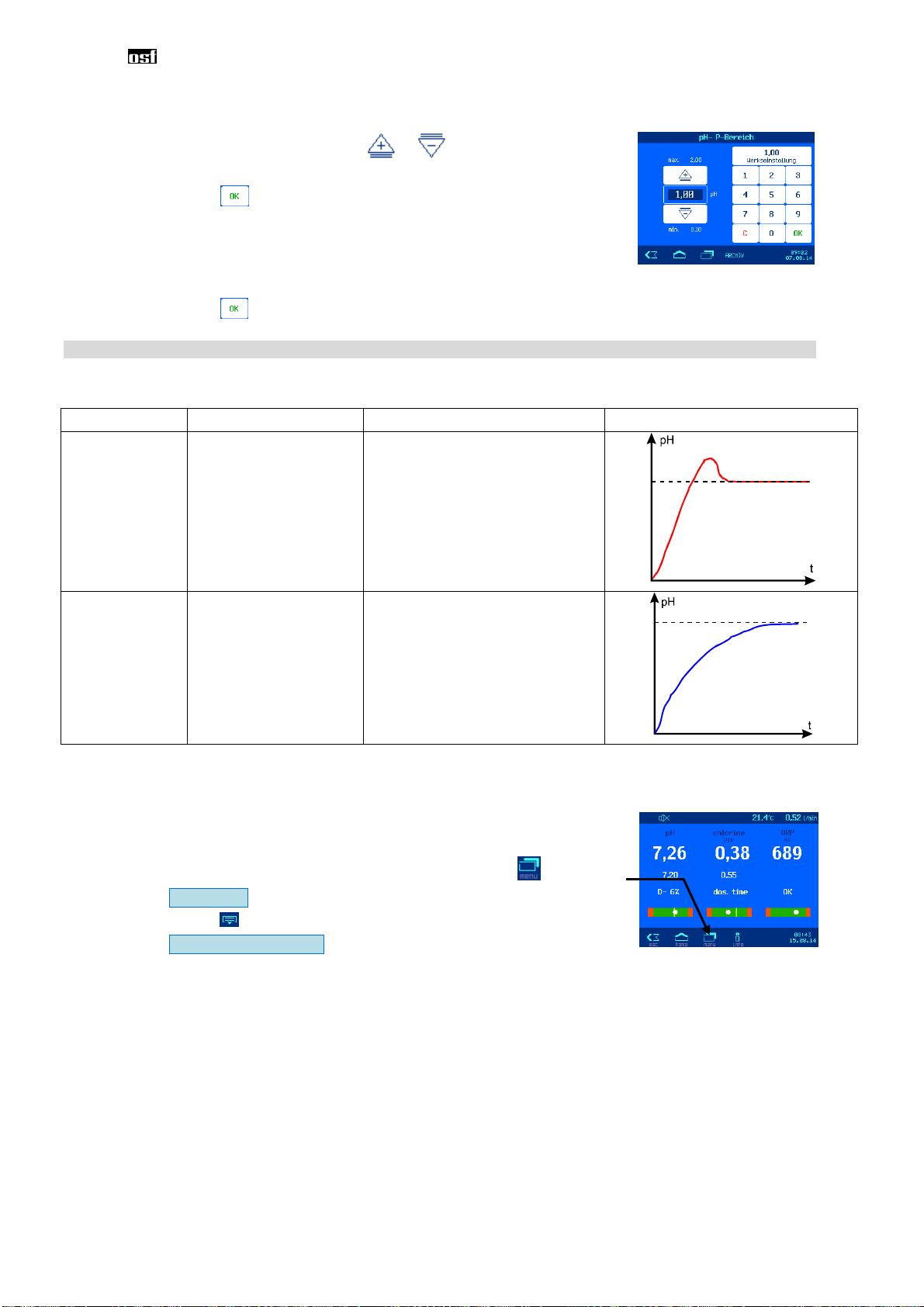
Setting the pH proportional range.............................................................................................................19
Impact of the proportional range ...............................................................................................................20
pH metering pump flow rate......................................................................................................................20
Chlorine regulation.........................................................................................................................................21
Switching chlorine regulation off or on......................................................................................................21
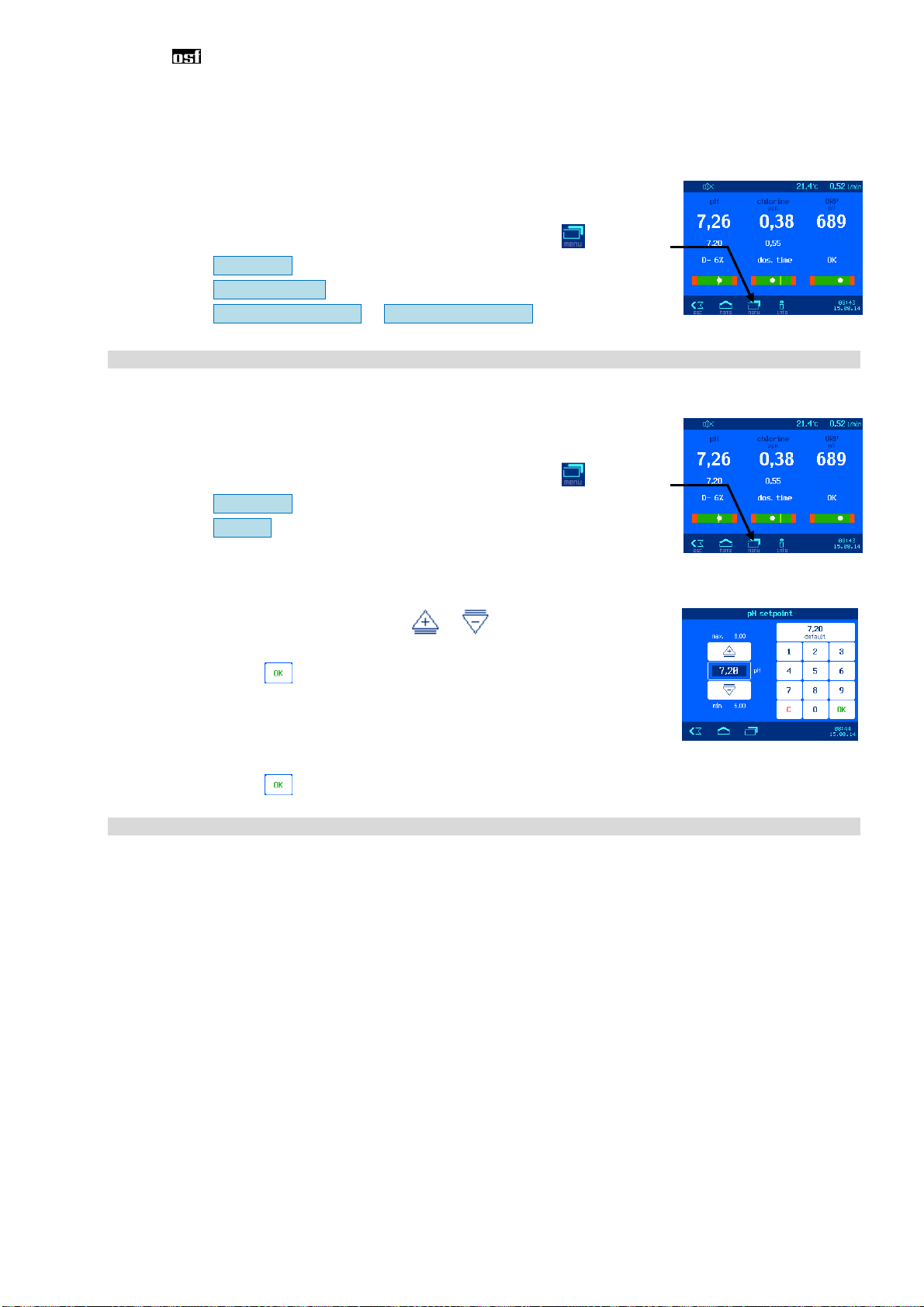
Setting the chlorine target value................................................................................................................21
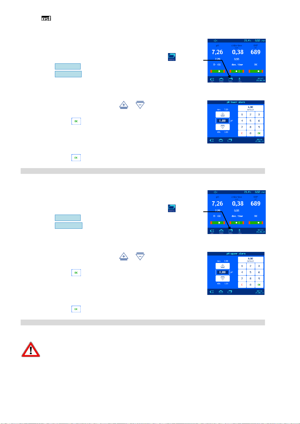
Setting the lower chlorine alarm................................................................................................................22
Setting the upper ORP alarm....................................................................................................................22
Calibrating the chlorine sensor..................................................................................................................22
Chlorine calibration errors.........................................................................................................................23
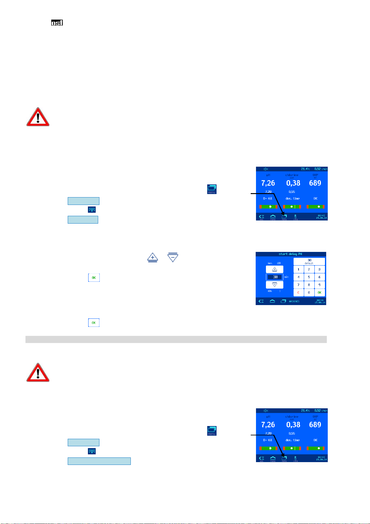
Power-on delay of chlorine regulation.......................................................................................................23
Setting the maximum chlorine metering time............................................................................................24
Setting the chlorine proportional range.....................................................................................................24
Impact of the proportional range ...............................................................................................................25
Chlorine metering pump flow rate.............................................................................................................26
ORP display ....................................................................................................................................................26
Setting the lower ORP alarm.....................................................................................................................26
Setting the upper ORP alarm....................................................................................................................27
Setting the ORP power on delay...............................................................................................................27
Calibrating the ORP electrode ..................................................................................................................28
ORP calibration errors...............................................................................................................................28
Info and alarm display....................................................................................................................................29
Acknowledgement of alarm messages .....................................................................................................29
Graph of measured values ............................................................................................................................29
Operating protocol .........................................................................................................................................30
Manual operation............................................................................................................................................30
Venting the dosing tubes...........................................................................................................................30
Shock chlorination.....................................................................................................................................30
Flocculation (Option) .....................................................................................................................................30
Setting the capacity of the flocculation pump............................................................................................30
Switching the flocculation off or on............................................................................................................31
Venting the flocculation tube.....................................................................................................................31
Settings for the service technician...............................................................................................................31
Settings for the real time clock..................................................................................................................31
Automatic Internet time .............................................................................................................................31
Time zone..................................................................................................................................................32
Manual time setting...................................................................................................................................32
Automatic daylight saving time..................................................................................................................32
Audible alarm ............................................................................................................................................32
Alarm settings............................................................................................................................................33
Restore factory settings.............................................................................................................................33
Setting for network operation ....................................................................................................................33
Using the -communication server ....................................................................................................33
Automatic IP address configuration (DHCP).............................................................................................34
Manual IP address configuration...............................................................................................................34
PIN-Numbers.............................................................................................................................................34
Language selection...................................................................................................................................34
Operating hours counter ...........................................................................................................................35

Installation and operating manual for WATERFRIEND -Chlorine MRD-3 Page 4
Device informations.................................................................................................................................. 35
Configuration of the metering pumps.......................................................................................................35
Raise pH <=> lower pH ............................................................................................................................ 35
Function of the third metering pump (option) ........................................................................................... 36
Bidirectional control for pH (pH+ and pH-) ............................................................................................... 36
Touchscreen calibration ........................................................................................................................... 36
Calibration of the temperature sensor......................................................................................................37
Additional settings via the LAN interface ................................................................................................... 37
Maintenance ................................................................................................................................................... 38
6-monthly service....................................................................................................................................... 38
Sealtightness............................................................................................................................................ 38
Dirt filter .................................................................................................................................................... 38
Injection valves......................................................................................................................................... 38
pH electrode ............................................................................................................................................. 38
ORP electrode.......................................................................................................................................... 38
Metering pumps........................................................................................................................................ 38
Annual service............................................................................................................................................ 38
Replacing ORP and pH electrodes ..........................................................................................................38
Replacing the metering hose.................................................................................................................... 38
Decommissioning.......................................................................................................................................... 39
Electrodes................................................................................................................................................. 39
Flow fitting................................................................................................................................................. 39
Metering pumps........................................................................................................................................ 39
Wear parts ...................................................................................................................................................... 39
Shipment of the dosing system ................................................................................................................... 41

Installation and operating manual for WATERFRIEND -Chlorine MRD-3 Page 5
General
Safety information
Installation and operating manual
This operating manual contains important information which must be observed during installation, operation
and maintenance of the metering unit. For this reason, it is imperative that this operating manual is read by
the fitter and the responsible specialist personnel or equipment owner before installation and initial start-up.
It must be continuously available at the device installation location.
Caution
The metering liquids used are corrosive or highly flammable. The two pressure hose ends at the hose pumps
must never be hanging freely, otherwise corrosive or highly flammable liquids can be discharged.
Canister
The canisters containing the metering liquids must be placed in interception troughs. They may never be
placed directly underneath the controller. Gas-emitting chemicals can cause damage to the sensitive
controller.
Personnel qualification
The personnel who will be operating, maintaining, inspecting and installing the device must have appropriate
qualifications for this work. The plant operator must precisely define the areas of responsibility,
responsibilities and monitoring of the personnel. If the personal does not have the required knowledge, they
must be trained and instructed. This can be carried out by the manufacturer or supplier on behalf of the
owner if required. Furthermore, the owner must ensure that the contents of this operating manual have been
understood by his personnel in all respects.
pH metering
pump
Chlorine metering
pump
Operating panel
Touch-Screen
Monitor
Dirt filter
Overview table for entering
calibrations carried out
Here, the buffer solutions are
set aside and stored
Flow rate
fitting
pH sensor ORP sensor
Drain valve
Measurement
water feed
Measurement
water return
Temperature
sensor
Chlorine sensor
Measuring water
flow sensor
Measuring
water control
valve
Option:
flocculation or pH+

Installation and operating manual for WATERFRIEND -Chlorine MRD-3 Page 6
Chlorine
pH
Filter
Chlorine metering
pH metering
Measurement water
Measurement
water return
Filter pump
WATERFRIEND MRD-3
Installation
You have purchased a high-quality measuring, regulating and metering device with the
WATERFRIEND. The device is a precise and sensitive system which needs to be handled carefully at all
times.
Please handle the protective cover carefully as well. It may not be allowed to fall down or come into contact
with chemicals. The protective cover should be cleaned using a soft cloth and a little water if necessary.
All regulations and provisions applicable to the place of installation must be observed during installation.
The swimming pool must be constructed such that a possible technical malfunction, power failure or a
defective metering system may not cause any consequential loss.
Mounting
The bottom housing section is fixed vertically and permanently to a solid wall with suitable load-bearing
capacity. Please ensure that the measuring cells are vertical after this has been carried out. The installation
location must be protected against dust and water in order to guarantee correct and proper functioning of the
device. The surrounding temperature must be between -0°C und + 40°C and should be kept as constant a s
possible. Humidity at the installation site may not exceed 95%, and no condensation may take place. Please
avoid direct heat or sun irradiation onto the device.
Installation in the water circuit
Please observe all valid safety regulations when carrying out installation work, and ensure that this is carried
out carefully. Disconnect the measuring, regulation and metering device and all other electrical consumers
such as filter pumps and heaters from the power supply.
Schematic

Installation and operating manual for WATERFRIEND -Chlorine MRD-3 Page 7
Measurement water pump
The dosing "WATERFRIEND" requires a continuous supply of sample water with a water amount of 0.3 to
1.0 liters per minute. When using filter pumps with variable displacement or in unfavorable pressure
conditions of the eventual use of a sample water pump must be checked.
General informational installation in the water circuit
•Before carrying out initial start-up, ensure that the injection valves open and close reliably.
•All hoses must be routed free of kinks.
•Avoid routing hoses over sharp edges.
•Connect all hoses carefully and check to ensure that they are tightly fitted to their connections.
•Avoid unnecessarily long hose lengths.
•Hoses may not be routed directly over pipes carrying heat or over other devices.
Electrical connection
The controller must be mounted protected against moisture in accordance with its protection class. The
device must be powered via a multi-pole main switch with a contact opening width of at least 3mm and a
residual current circuit breaker with I
FN
≤30mA. The device must be isolated before opening the housing.
Electrical power supply connections, in addition to alignment and service work, may only be carried
out by approved electricians. The attached circuit diagrams and all applicable safety regulations
must be observed.
Low-voltage cables
Low-voltage cables may not be routed together with three-phase or alternating current cables in one cable
duct. Routing of low-voltage cables in the vicinity of three-phase or alternating current cables should
generally be avoided.

Installation and operating manual for WATERFRIEND -Chlorine MRD-3 Page 8
Wiring diagram
Steckverbinder
connector
Steckverbinder
connector
Dosierpumpe pH
dosing pump pH
Dosierpumpe Chlor
dosing pump chlorine
Niveau Sensor pH
level sensor pH
Niveau Sensor Chlor
level sensor chlorine
Lvl 1 Lvl 2
Netz mains
1 / N / PE 230V 50Hz
N
L
1
Sicherung
fuse
T2A
Alarm
Freigabe (Filtersteuerung)
enable (pool control)
Alarm
Data-
Data+
RS 485
Control Board
Steckverbinder
connector
Dosierpumpe Chlor
dosing pump chlorine
Steckverbinder
connector
Pumpe 3
pump 3
Niveau Sensor Pumpe 3
level sensor pump 3
Lvl 3
P
W
M
3
P
W
M
4
Externe Pumpe Flockung
external pump flocculation
Externe Pumpe pH +
external pump pH +
P
W
M
1
P
W
M
2
Externe Pumpe Chlor
external pump chlorine
Externe Pumpe pH -
external pump pH -
Alarm
An external acoustic or optical alarm can be connected to these terminals. These terminals can also be used
for connection to group error messaging systems. The terminals can be loaded with maximum 230V 1A.
External pumps
These connecting terminals are control contacts for external metering pumps. The terminals can be loaded
with maximum 230V 1A.
Enabling
At these terminals the dosing enable signal of the filter control system must be connected. The opening of
the floating contact within the filter control interrupts the dosing. The filter control must ensure by this signal
that dosing will only be enabled when there is sufficient water flow at the injection point.
RS-485
These terminals are used for connection to the Euromatik.net or the Pool-Control-TOUCH filter
control unit. A screened, twisted, 2-core cable (twisted pair) with a cross-section of at least 0.22 mm2 is
required for the connection. (e.g. Li2YCY(TP) 2 x 0.22 mm²). Screening improves the electromagnetic
compatibility (EMC). The cable length of the complete bus-system may not exceed 1200 m. The polarity
(DATA+ and DATA) should be observed.
Connecting to the computer network
Connection to the Internet is carried out by the communication server. The WATERFRIEND MRD-3 is
connected using a standard Ethernet patch cable into the network wall outlet, the powerline adapter, the
wireless LAN access point or other suitable facilities.

Installation and operating manual for WATERFRIEND -Chlorine MRD-3 Page 9
After the WATERFRIEND was connected to an active network outlet, the power supply can be turned on.
The web server in WATERFRIEND now searches autonomously for the communication server and logs on
to the database.
If the "OSF" icon in the monitor is visible (see chart), the WATERFRIEND has logged on to the
communication server.
Using the -communication server
You can reach the -communication server at the address http://devices.osf.de
As a new user, you must register first:
Network line / patch cable
Network
outlet
LAN connection
established
OSF
Connected to
communications
server

Installation and operating manual for WATERFRIEND -Chlorine MRD-3 Page 10
After registering, you can log in and then add a new device to your user profile by entering the device ID of
the dosing control in the appropriate field:
The DEVICE ID of your device is shown on the device information page on the control panel of the device.
Read device ID on the display of the dosing control
⇒
After that, your device will appear in your device overview and can be operated using the communication
server:
For the use of the communication server, the Internet connection via the communication server must be
enabled (Factory setting).

Installation and operating manual for WATERFRIEND -Chlorine MRD-3 Page 11
www.osf.de
MADE IN GERMANY
Touchpanel
Temperature
The displayed temperature is the measurement water temperature within the flow fittings. This can deviate
from the actual water temperature in the swimming pool depending on the pipeline routing and surrounding
temperatures.
Measurement water flow quantity
Quantity of water flowing through the fittings. Teh chlorine regulation only works with a flow rate in the range
between 0,3 and 1,0 l/min.
Measurement water
flow rate
Power indicator
Escape key
Abort without
saving changes Time
Date
Home Menü Info-Key
POWER
Measurement water
temperature
Audible
alarm
Child lock

Installation and operating manual for WATERFRIEND -Chlorine MRD-3 Page 12
Display
Analog display
Setpoint Current value
Current pH value
Setpoint pH
Regulation status
Analog display pH
Current chlorine value
Setpoint chlorine
Regulation status
Analog display chlorine
Current ORP value
www.osf.de
MADE IN GERMANY
MRD
-
3
CHLOR

Installation and operating manual for WATERFRIEND -Chlorine MRD-3 Page 13
Initial setup
Select language
Set date and time
By pressing the keys + rsp. –. The current time and date can be set. The
settings have to be saved by pressing the OK key.
Adjust the flow rate of the measurement water
1. Read the current flow rate on the display.
2. Using the measuring water flow control valve, adjust the flow rate to 0,5 l/min. At flow rates below 0.3
l/min or above 1.0 l/min an exact maesuremant oft he chlorine concentration is not possible, and the
automatic chlorine dosation is inhibited.
Calibrate the sensors
Turn on automatic dosing
In order to achieve good water quality, it is useful to operate the metering system a few days without
automatic dosage before the calibration is performed. Otherwise, the calibration must be repeated
after a few days.
Set delivery performance of metering pumps
The speed control of the metering pumps allows adjustment of the flow to the pool size. For the calculation of
the flow following rule of thumb can be used:
The result of this calculation, however, is a guide only. The system characteristic values of the swimming
pool, for example filter pump output, pipe lengths, temperature, usage behavior, etc. are not included in the
formula.
Flow control valve
Pool volume in m³
100 = delivery rate in l/h
Display of flow rate

Installation and operating manual for WATERFRIEND -Chlorine MRD-3 Page 14
Operation
Symbol bar
Key bar
Child lock
This symbol shows the status of the child lock.
OFF (no symbol) ON
26,7°C
0,6 l/min
26,7°C
0,6 l/min
On delivery, the child lock is switched off.
Activate the child lock Briefly touch this area on the screen with a finger
26,7°C 0,6 l/min
Deactivate the child lock: Press the key symbol 5 seconds with a finger
26,7°C 0,6 l/min
When the child lock is active, all keys are locked!
Professional mode (expert level)
The WATERFRIEND provides protection against unwanted adjustment of important operating parameters.
On delivery this protection function is activated. All functions shown in gray on the display are then locked.
Protection ON (no symbol) Protection OFF
26,7°C
0,6 l/min
26,7°C
0,6 l/min
To turn off protection function, the key line is touched
with a finger and swept from right to left.
(Note icon at top left of the symbol line)
One hour after the last touch of a button, the protection function is
automatically turned on again.
To activate the protection function, the key line is again touched with a
finger and swept from right to left. (Note the icon at top left of the
symbol line).
In professional mode statistics are stored on different
menu pages. By pressing the corresponding symbol,
these statistics can be viewed.
ARCHIV

Installation and operating manual for WATERFRIEND -Chlorine MRD-3 Page 15
pH regulation
In this menu you can adjust various settings of the pH control.
Switching pH regulation on or off
Procedure:
Press the key
1. Select pH settings
2. Select Operating mode
3. Select Operation mode OFF or Operation mode Auto
The selected setting is stored automatically.
Factory setting: Operation mode AUTO
Setting the pH target value
There is a setting facility for the required pH value in the menu.
Procedure:
Press the key
1. Select pH settings
2. Select Setpoint
The current setpoint is shown on the left side of the display.
To adjust this value, the following two options are available:
a) PLUS / MINUS keys
•By pressing the arrow keys or , the value can be
modified stepwise.
•Press to store the new setting.
b) Keyboard
The setpoint can also be set directly by using the keyboard on
the right side of the display:
•enter the desired value
•Press to store the new setting.
Factory setting: 7,2 Range: Between lower alarm limit and upper alarm limit

Installation and operating manual for WATERFRIEND -Chlorine MRD-3 Page 16
Setting the lower pH alarm
There is a setting facility for the required alarm limit value in the menu.
Procedure:
Press the key
1. Select pH settings
2. Select lower alarm
The current value is shown on the left side of the display.
To adjust this value, the following two options are available:
a) PLUS / MINUS keys
•By pressing the arrow keys or , the value can be
modified stepwise.
•Press to store the new setting.
b) Keyboard
The value can also be set directly by using the keyboard on the
right side of the display:
•enter the desired value
•Press to store the new setting.
Factory setting: 6,0 Range: from 3,0 to regulation target value (setpoint)
Setting the upper pH alarm
There is a setting facility for the required alarm limit value in the menu.
Procedure:
Press the key
1. Select pH settings
2. Select upper alarm
The current value is shown on the left side of the display.
To adjust this value, the following two options are available:
a) PLUS / MINUS keys
•By pressing the arrow keys or , the value can be
modified stepwise.
•Press to store the new setting.
b) Keyboard
The value can also be set directly by using the keyboard on the
right side of the display:
•enter the desired value
•Press to store the new setting.
Factory setting: 8,0 Range: from regulation target value to 9,99
Calibrating the pH electrode
Calibration should only be performed by an expert and is only accessible in Expert Mode.
Once the sensors have been connected, every input must be calibrated during initial start-up. Calibration is
necessary even if an electrode is replaced by a new one. The WATERFRIEND checks the calibration
procedures for plausibility during the process (slope and offset). Non-calibrated and "badly" calibrated
measurement inputs are displayed in plain text.
Time delays occur due to the electrode start-up times when the device is switched on.

Installation and operating manual for WATERFRIEND -Chlorine MRD-3 Page 17
The use-by date must be observed for the buffer solutions The solutions must always be stored in a cool,
dark place. Buffer solutions may not be soiled during use. For this reason, electrodes may not be immersed
in different buffer solutions successively without cleaning them with distilled water first. It is also important not
to rub the electrodes with a cloth, because this causes static charging and incorrect measurements. The
necessary buffer solutions for pH 4, pH 7 and for ORP 468mV and spare electrodes are available
from the "WATERFRIEND“ metering unit supplier.
The electrodes must be free of impurities, oils and fats etc before they are inserted in the flow fittings.
Furthermore, the diaphragms (small spots at the probe point) must be free of coatings, soiling and
crystallisation deposits. Do not touch the glass body with your hands to avoid impurities.
The calibration is carried out as a 2-point calibration with 2 buffer solutions. These buffer solutions must be
free of impurities and fresh.
During the calibration, the measured electrode value and the pH values for the buffer solutions set are
shown in the display. You can use these displayed values to ascertain the quality of the electrode during the
calibration.
Calibrating the upper value (pH 7)
Procedure:
Press the key
1. Select pH settings
2. Select Calibration
In the first stage, the upper point (pH 7) is calibrated. To do this, the pH electrode is immersed in a buffer
solution of pH 7. The current values for the pH electrode are then shown in the display. When the value in
the display does not change any more, you can either
select end calibration
or
Single-point calibration (pH):
The calibration is complete. The offset value is
accepted and stored
select to 2. point Two-point calibration (pH):
Continue to calibration of lower value (pH 4)
Calibrating the lower value (pH 4)
In the second stage, the lower point (pH 4) is calibrated. To do this, the pH electrode (which must have been
cleaned in distilled water first) is immersed in a buffer solution of pH 4. The current values for the pH
electrode are then shown in the display. When the value in the display does not change any more, press end
calibration to store the new offset and slope values of the sensor.
Caution: It is also important not to rub the electrode with a cloth, because this causes static charging and
incorrect measurements.
Once calibration is complete, the slope and offset of the electrode are shown in the display.
If the offset difference falls below a value of ± 60mV, the calibration cannot be correctly completed. The
display shows the message Big divergence.
The slope must be in a range between 45.0 and 65.0 mV. If not, the calibration cannot be correctly
completed. The display shows the message Big divergence.
If the electrode values are outside specific tolerances, a message is shown to alert you to this fact. If this is
the case, the electrode should be replaced as soon as possible.
pH calibration errors
If the calibration was not able to be completed and the Big divergence is shown in the display, the following
causes are possible:
•The pH electrode (combination electrode) is worn. The electrode service life is limited depending on
the water quality and its care.
•You have mixed up the buffer solution sequence (1st pH 7, 2nd pH 4). This sequence must be
strictly observed.
•You used the same buffer solution twice. Correct calibration can only be carried out with two different
buffer solutions.

Installation and operating manual for WATERFRIEND -Chlorine MRD-3 Page 18
•You used the wrong buffer solutions. It is imperative that pH 4 and pH 7 are used. Calibration is not
possible if other buffer solutions are used.
•The buffer solutions are used up or contaminated. In this case, use new buffer solutions.
•The electrode was connected to the wrong transmitter. The pH electrode must be connected to the
black transmitter.
•The electrical connection between electrode and transmitter, or that between transmitter and
controller, is damaged.
pH power on delay
This setting should only be adjusted by a professional, and is only accessible in Expert Mode.
The controller only starts up after a delay period once the power supply has been provided and once
external enable has been switched on (e.g. filter control unit). This power-on delay is necessary because a
period specific to the overall system elapses once the filter pumps have been switched on before the
completely mixed water reaches the sensors. This mixing process is mainly dependent on the pool size, the
dimensions of the filter pump, the pipe length and the filter itself.
The delay period can, if required, be adapted to the actual pool size.
Procedure:
Press the key
1. Select pH settings
2. Press the key in the key bar
3. Select Start delay
The current value is shown on the left side of the display.
To adjust this value, the following two options are available:
a) PLUS / MINUS keys
•By pressing the arrow keys or , the value can be
modified stepwise.
•Press to store the new setting.
b) Keyboard
The value can also be set directly by using the keyboard on the
right side of the display:
•enter the desired value
•Press to store the new setting.
Factory setting: 30 minutes Range: 1 to 120 minutes
Setting the maximum pH metering time
This setting should only be adjusted by a professional, and is only accessible in Expert Mode.
The metering time limit is a safety function and prevents dangerous overdosing in cases of breakdown.
Attention! The higher the maximum dosing time is set, the more acid can be released in an uncontrolled
manner in case of any damage of the dosing tube.
The metering time must be adapted to the actual pool size.
Procedure:
Press the key
1. Select pH settings
2. Press the key in the key bar
3. Select Maximum dosage time
The current value is shown on the left side of the display.

Installation and operating manual for WATERFRIEND -Chlorine MRD-3 Page 19
To adjust this value, the following two options are available:
a) PLUS / MINUS keys
•By pressing the arrow keys or , the value can be
modified stepwise.
•Press to store the new setting.
b) Keyboard
The value can also be set directly by using the keyboard on the
right side of the display:
•enter the desired value
•Press to store the new setting.
Factory setting: 60 minutes Range: 1 to 300 minutes
Setting the pH proportional range
This setting should only be adjusted by a professional, and is only accessible in Expert Mode.
The controller offers the facility for setting the regulation proportional range in order to adapt the
WATERFRIEND to the requirements of the specific swimming pool. This value influences the delivery
quantity by optimising the pulse-width modulation. This means that the duty cycle is modulated at constant
frequency. The numeric value specifies the regulating conductance. At a deviation of the measured actual
value from the desired value, which is greater than the P range, the metering pump operates with maximum
power. If the actual value approaches the target value inside the proportional range, the metering
performance decreases proportionally. This means that the pump is working at reduced power.
Increasing the p-range leads to a slower approach to the target value
with less overshoot.
Procedure:
Press the key
1. Select pH settings
2. Press the key in the key bar
3. Select P-range
The current value is shown on the left side of the display.

Installation and operating manual for WATERFRIEND -Chlorine MRD-3 Page 20
To adjust this value, the following two options are available:
a) PLUS / MINUS keys
•By pressing the arrow keys or , the value can be
modified stepwise.
•Press to store the new setting.
b) Keyboard
The value can also be set directly by using the keyboard on the
right side of the display:
•enter the desired value
•Press to store the new setting.
Factory setting: 1,00 Range: 0,1 to 2,0
Impact of the proportional range
Adjustment Benefits Disadvantages Diagram
Small P-range Fast, accurate control When switching on an overshoot
can occur
Wide P-range No overshoot Slow control, small deviations
between desired and actual
values possible
pH metering pump flow rate
The integrated speed control for the metering pumps enables optimum
adaptation of the regulation to the pool size.
Procedure:
Press the key
1. Select pH settings
2. Press the key in the key bar
3. Select Capacity dosing pump
The current value is shown on the left side of the display.
Table of contents
Popular Water System manuals by other brands

Ultimate Solar
Ultimate Solar 1K HE3 Installation and user manual

Aquatec
Aquatec Watermaker AC 65 Technical manual

Presto
Presto Q4357 installation instructions

Vollrath
Vollrath Sous Vide 60038 Operator's manual

Hellenbrand
Hellenbrand PM6.O-IC-2.0 Series brochure

Riello
Riello Dialog Plus 300 instruction manual

Watts
Watts FEBCO 860 Small Series installation instructions

Ecolab
Ecolab Formula1 Installation & operation manual

aarke
aarke CARBONATOR 3 user guide

Enapter
Enapter WT 2.1 owner's manual

Crystal Quest
Crystal Quest CQE-UV-00101 Installation and operation guide

Halsey Taylor
Halsey Taylor HVRGRN8WSNF 1B Series Installation, care & use manual