FEB 825YA Owner's manual
INSTALLATION, OPERATION, MAINTENANCE
IOM-F-825_826
Operation and Maintenance Manual
Reduced Pressure Backflow Prevention Assemblies
Models 825Y, 825YA, 825, 825D, 825YD & 826YD
Read and understand this manual prior to installing,
operating or servicing this equipment.
TABLE OF CONTENTS
Features and Operating Procedures . . . . . . . . . . . . . . . . . . . . . . . . . . . . . . . . . 2
Installation Guidelines . . . . . . . . . . . . . . . . . . . . . . . . . . . . . . . . . . . . . . . . . . . . . 3
Freeze Protection Procedures . . . . . . . . . . . . . . . . . . . . . . . . . . . . . . . . . . . . . . 4
Vandalism Protection Procedures . . . . . . . . . . . . . . . . . . . . . . . . . . . . . . . . . . . 5
General Service Procedures . . . . . . . . . . . . . . . . . . . . . . . . . . . . . . . . . . . . . . . . 6
Troubleshooting Procedures and Guide . . . . . . . . . . . . . . . . . . . . . . . . . . . . 7, 8
Field Testing Procedures . . . . . . . . . . . . . . . . . . . . . . . . . . . . . . . . . . . . . . . 9, 10
Service Procedures Model 825Y (3/
4
–2") . . . . . . . . . . . . . . . . . . . . . . . 11, 12, 13
Parts Lists and Part Numbers Model 825Y (3/
4
–2") . . . . . . . . . . . . . . . . . . 14, 15
Exploded View of Model 825Y (3/
4
–2") . . . . . . . . . . . . . . . . . . . . . . . . . . . . . . . 15
Service Procedures Models 825, 825D and 825YD (21/
2
–3") . . . . . . . . . . 16, 17
Service Procedures Models 825, 825D and 825YD (4–10") . . . . . . . . . . . 18, 19
Parts Lists and Part Numbers Model 825 (21/
2
–10”) . . . . . . . . . . . . . . . . . 20, 21
Exploded View of Model 825 (21/
2
–10") . . . . . . . . . . . . . . . . . . . . . . . . . . . . . . 21
Parts Lists and Part Numbers Models 825D and 825YD . . . . . . . . . . . . . . . . 22
Exploded View Models 825D and 825YD . . . . . . . . . . . . . . . . . . . . . . . . . . . . 23
Parts List and Exploded View of Model 825D and 825YD Check Assembly 24
Parts List and Exploded View of Model 825 and 825D Relief Valve . . . . . . . 25
Parts List and Exploded View of Model 825YD Relief Valve . . . . . . . . . . . . . 26
Parts List and Exploded View of Model 826YD Relief Valve and Bypass . . . 27
Service Procedure Relief Valve Models 825, 825D and 825YD (21/
2
–10") 28, 29
Spring Removal Tool Instructions Model 825 (21/
2
–10") . . . . . . . . . . . . . . . . . 30
Commercially Available Parts Lists . . . . . . . . . . . . . . . . . . . . . . . . . . . 31, 32, 33
How To Order Parts . . . . . . . . . . . . . . . . . . . . . . . . . . . . . . . . . . . . . . . . . . . . . 34
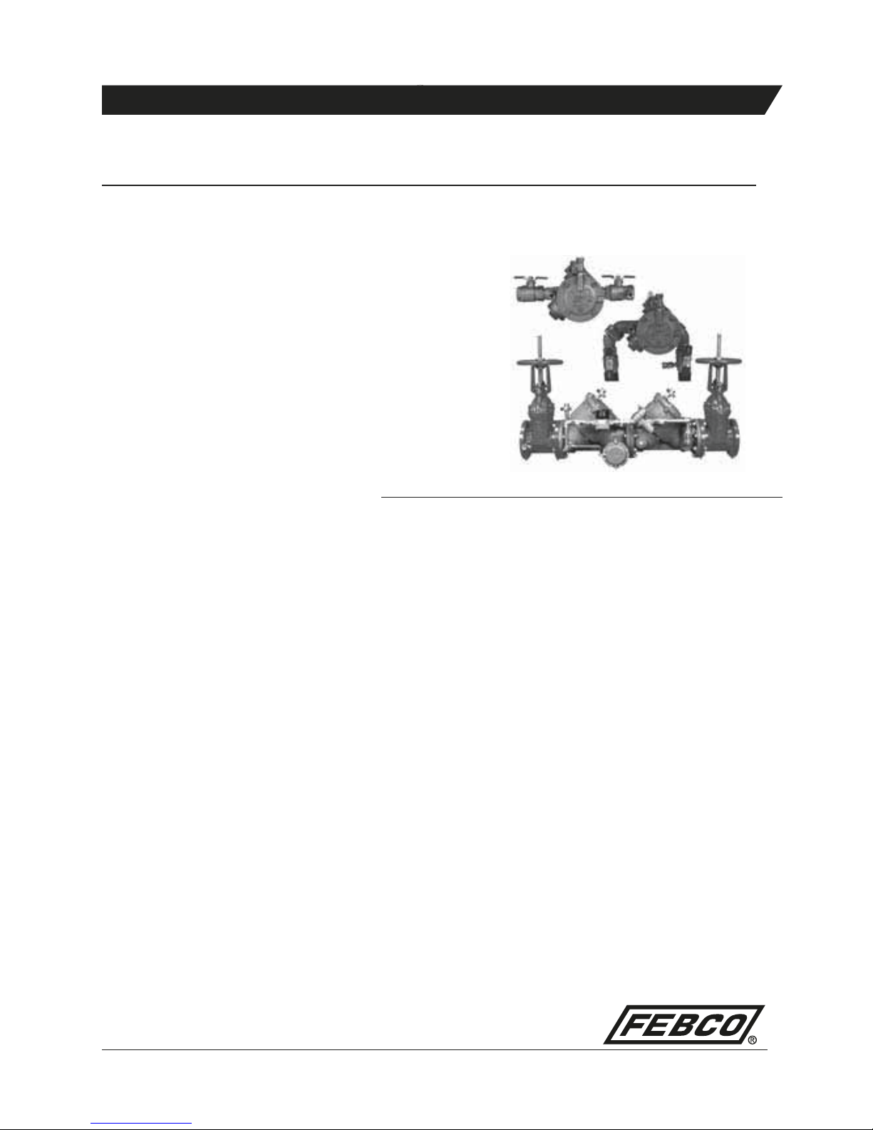
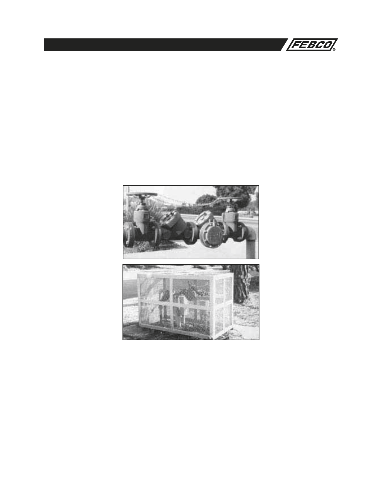
Series 825Y
Series 825YA
Series 826YD
2
MAINTENANCE MANUAL MODELS 825Y, 825YA, 825, 825D, 825YD & 826YD
Feature and Operating Procedures
FEBCO manufactures several models of Reduced Pressure Backflow
preventers. The Model 825Y and 825YA are available in sizes 3/4–2"
with bronze body and cover as standard. Other materials are avail-
able. The FEBCO Model 825 sizes 21/2–10" were manufactured with
cast iron. The FEBCO Model 825 Type D and 825 Type YD sizes
21/2"–10" are manufactured with standard body material of ductile
iron.
The FEBCO Reduced Pressure Backflow preventer assembly con-
sists of two independently operating, spring loaded check valves
with a pressure differential relief valve located between the two
checks. The pressure drop across the first check valve is approxi-
mately 6.0 psid with no flow. The relief valve consists of a hydrauli-
cally balanced diaphragm with the high pressure side hydraulically
connected to the upstream side of the first check. The low pres-
sure side is hydraulically connected to the reduced pressure zone,
thus the relief valve remains closed during normal operation. The
low pressure side of the diaphragm is spring loaded to force the
relief valve open when the pressure drop across the first check (and
across the diaphragm) reduces to approximately 2.5 psid. A com-
plete assembly includes two shut-off valves and four test cocks.
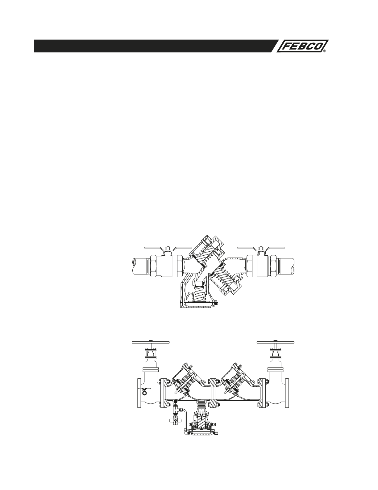
Example sectional views below show typical components and flow
passages with corresponding pressure readings (no flow conditions)
at the various locations within the assembly.
Reduced Pressure Backflow Preventer
*Relief Valve
Rotated 90º for Clarity
Model 825Y (3/4–2")
Figure No. 1
Model 825YD (21/2–10")
Figure No. 2
Inlet Shutoff Outlet Shutoff
First Check Second Check
100 PSI
93 PSI
Relief Valve*
Reduced
Pressure
Zone
*Relief Valve
Rotated 90º for Clarity
94
PSI
94 PSI
Inlet Shutoff Outlet Shutoff
First Check
Second Check
100 PSI 93 PSI
Relief Valve*
3
MAINTENANCE MANUAL MODELS 825Y, 825YA, 825, 825D, 825YD & 826YD
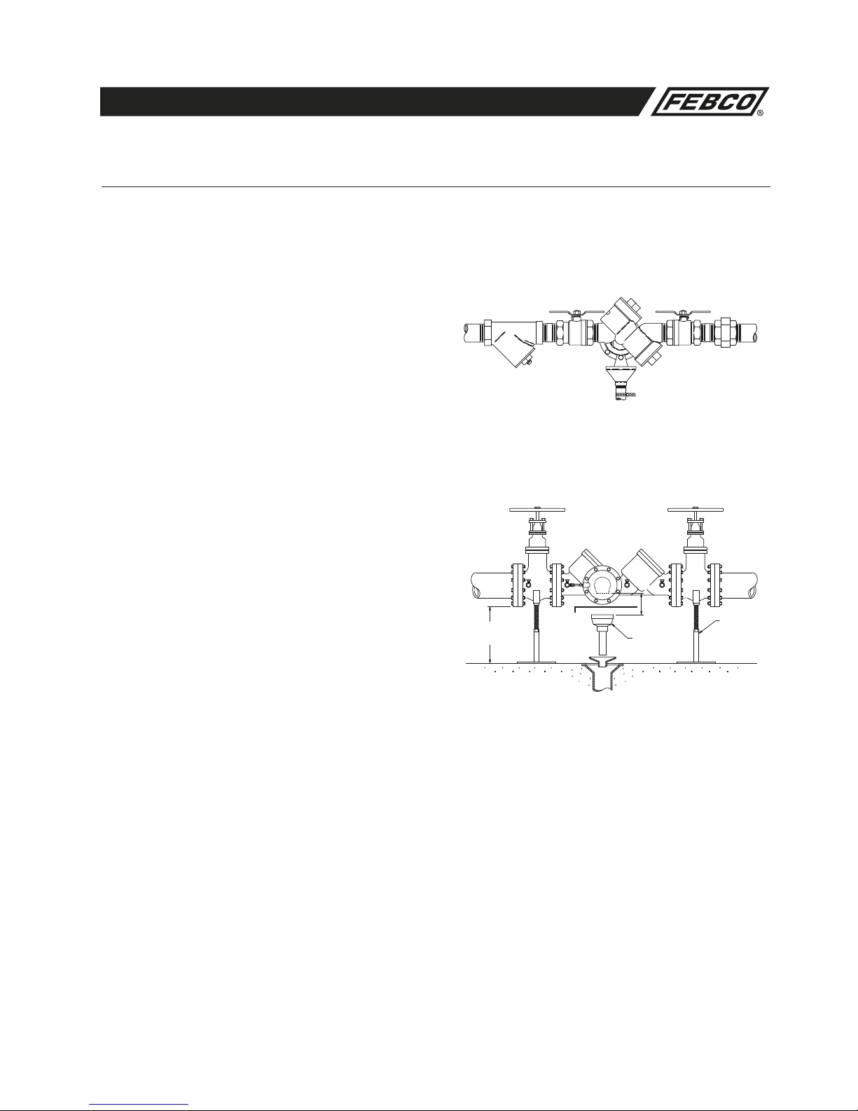
1. The assembly should be installed in a horizontal position with a
minimum clearance of 12" between the relief valve discharge
port and floor or grade, and a minimum of 18" horizontal clear-
ance around the unit for access and ease of testing and
maintenance of the relief valve.
2. Approval agencies do not recommend installation of a
Reduced Pressure Assembly in a pit. Flooding of the pit can
result in cross connection contamination. If local codes permit
installation of a Reduced Pressure Assembly in a pit, adequate
drainage must be provided to prevent the pit from flooding
under maximum discharge conditions.
3. Placement of the assembly should be planned where water
discharged from the relief port will not be objectionable or
cause damage to property and/or equipment.
4. To be approved by the University of Southern California
Foundation for Cross-Connection Control and Hydraulic
Research (USC), the assembly must be purchased and
installed with resilient seated shutoffs to ensure bubble tight
closure for more consistent results during testing. CAUTION:
Open and close resilient seated shut-offs slowly to prevent
water hammer damage to the system and assembly.
5. Since the FEBCO Reduced Pressure Assembly is designed to
be serviced while in line, the unit need not be removed from
the line during servicing.
6. Ensure the supply water pressure does not exceed the manu-
facturer’s maximum water pressure rating of the assembly to
avoid damage to the system or the assembly caused by sys-
tem pressure. In addition, protection must be provided against
thermal water expansion, extreme backpressure and/or water
hammer.
7. Most field problems occur because dirt or debris present in
the system at the time of installation becomes trapped in
the first check seating area resulting in continuous discharge
from the relief valve in a static or backflow condition. THE
SYSTEM SHOULD BE FLUSHED BEFORE THE ASSEMBLY
IS INSTALLED. However, to effectively flush the system after
the assembly has been installed, remove the internal compo-
nents of both checks and open the inlet shut-off to allow water
to flow for a sufficient time to flush debris from the line and
assembly. If debris In the water system continues to cause
fouling, a strainer can be installed upstream of the assembly.
Installation Guidelines
Proper installation of the assembly is essential to the protection of the water supply
Typical Installations
Figure No. 3
Air Gap Drain
Drain Support
Flow
Wye Strainer
Figure No. 4
Flow
30" Max.
12" Min. Air Gap
Drain
Support
3"
and
Larger
Maintain
approved
air gap
distance
Indoor Installation
4
MAINTENANCE MANUAL MODELS 825Y, 825YA, 825, 825D, 825YD & 826YD
Freeze Protection
Procedure
The reduced pressure backflow prevention assembly is subject to
damage if the internal water is allowed to freeze. It is suggested
that all assemblies be installed with resilient seated shutoffs so
that a drip tight closure can be achieved to prevent refilling of
the assembly after the freeze protection procedure is performed.
The unit must be protected from freezing by a heated enclosure,
draining, insulation using heat tape, or other suitable means.
However, the unit must always be accessible for testing and
maintenance. If the system will be shut down during freezing
weather, use the following procedure to
drain internal passages.
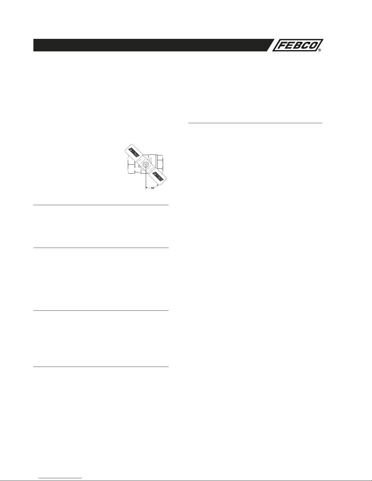
The Model 825YA can be removed from
the line as a winterizing procedure. See
Figure 5 for proper ball valve procedure.
Model 825Y (3/4–2") Reduced
Pressure Zone and Relief
Valve Freeze Protection
1. Slowly close the main shutoff valve upstream
of the assembly, which provides water to the system.
2. Drain system water upstream of the first check
by means other than through the assembly.
Check Valve Draining Procedure
3a. First check (zone) Open #2 and #3 test cocks. All water
between the first and second check valves will drain through
the relief valve port.
3b. Second check (downstream)—Remove the second check
cap, spring and disc holder. All water downstream of the
second check (that is higher than the outlet shutoff valve) will
drain through the body.
Relief Valve Draining Procedure
4a. If device is equipped with optional drain plugs, remove plugs
in the relief valve cover and body. Open #2 and #3 test cocks.
All water will drain through plug holes.
4b. For standard models (not equipped with optional drain plugs)
loosen the relief valve cover and allow water to drain from
both sides of the diaphragm.
Ball Valve ShutOff Draining Procedure
5a. If the assembly has been installed with ball valve shutoff
valves, they must also be properly drained to prevent freeze
damage. After draining procedure has been completed on the
backflow prevention assembly, position all ball valve shut-offs
and test cocks in a half open/half closed (45 degree) position.
(see Figure 5)
5b. Open the ball valve approximately 45 degrees while draining
the pipeline and assembly to allow water between the ball
and valve body to drain. Leave the ball valve in this position
for the winter to prevent freeze damage.
5c. The ball valves must be fully closed before the system is
repressurized. OPEN AND CLOSE BALL VALVES SLOWLY
TO PREVENT DAMAGE TO THE SYSTEM CAUSED BY
WATER HAMMER.
Model 825, 825D and 825YD (21/2–10")
Reduced Pressure Zone and Relief Valve
Freeze Protection
1. Slowly close supply valve within freeze protected area, open
air bleed valves on No. #1 check valve and relief valve (3
places), and open No. #2 and #3 test cocks. Water within the
zone will be drained to the lowest point of the relief valve
discharge port (relief valve seat). A minor amount of water will
remain in the bottom of the valve body, but this is not suffi-
cient to cause freezing damage.
2. With this procedure, about one-half of the relief valve will be
drained. To drain the relief valve on Models 825 and 825D,
loosen the relief valve cover bolts and allow the relief valve to
drain. Retighten bolts before repressurizing system. To drain
relief valve on Models 825YD, open the two air bleeds (one
on the body, the other on the cover), then remove drain plugs.
Replace drain plugs before repressurizing system.
3. The system design must provide a means for draining
upstream of the #1 check valve and downstream of the #2
check valve. Test cocks #1, #2, and #4 and the air bleed valve
on #2 check valve may be opened to allow air to enter to
assist in draining. Depending on system design, these sec-
tions should be able to be drained to the pipe centerline.
4. Position the assembly shutoff valves and test cocks in the
half open/half closed position to allow complete draining
of the assembly shutoff valve bodies and test cocks.
5. Some units contain a drain plug in the bottom of the second
check body. Open test cocks and remove plug to drain.
Figure No. 5
5
MAINTENANCE MANUAL MODELS 825Y, 825YA, 825, 825D, 825YD & 826YD
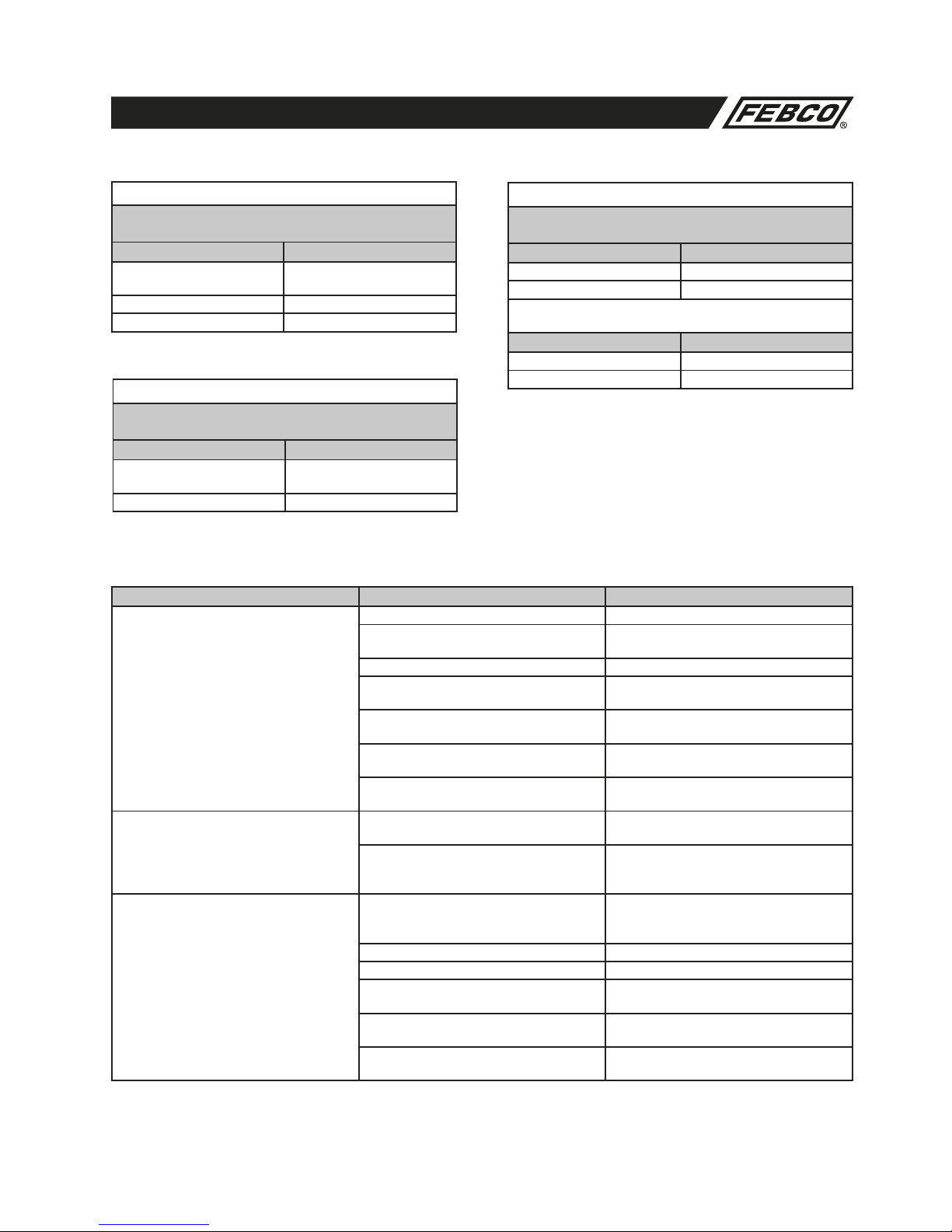
1. If the unit is installed where vandalism may be a problem, the
assembly should be protected and secured. On 3/4–2" units
the handles of shutoff valves can be removed to discourage
tampering. On 21/2–10" units a chain can be looped between
shutoffs and locked in position to prevent tampering with
shutoff valves. Test cock handles can also be removed. On
backflow prevention assemblies installed in conjunction with
fire sprinkler systems, an alarm can be placed on the OS&Y
shut-off valves that will sound if unauthorized closure should
occur.
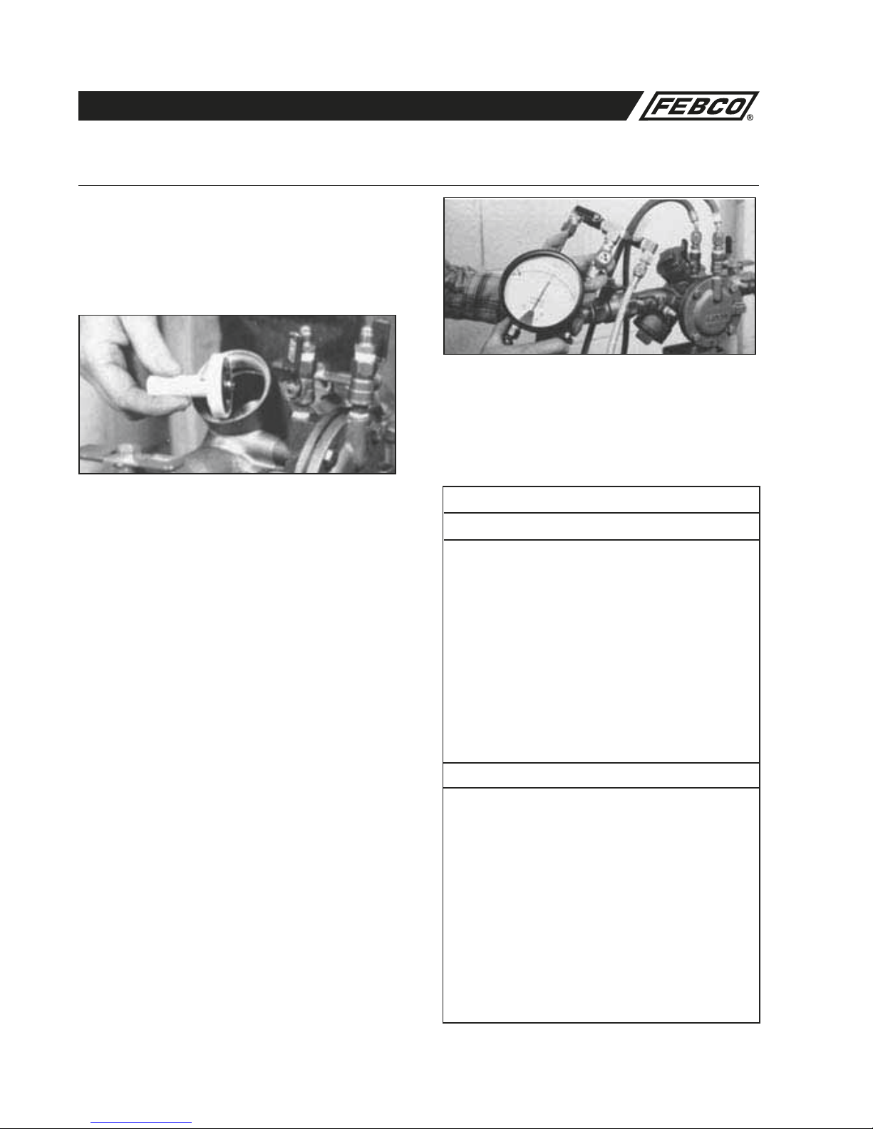
2. A protective cage can be installed over the unit to discourage
vandals. If a cage is used, it should be installed so that ade-
quate clearance is available for maintenance and testing or it
should be completely removable. Also allow for any discharge
from the relief valve to fully drain from the protective cage.
3. Some units include screw driver adjusted test cocks for vandal
resistance.
Vandalism Protection Procedure
6
MAINTENANCE MANUAL MODELS 825Y, 825YA, 825, 825D, 825YD & 826YD
1. FEBCO backflow prevention assemblies can be serviced with
commonly available tools and are designed for ease of mainte-
nance. The assemblies are designed to be serviced in line, so
the unit should not need to be removed from the line during
servicing.
2. The most common cause of check fouling and relief valve dis-
charge is dirt and debris in the seating areas. The line should
be flushed clean of debris before installation of the assembly.
To flush the line after installation of the assembly, slowly close
the inlet shutoff valve, remove the covers and internal assem-
blies of both check valves and open the inlet shutoff valve to
allow sufficient flow of water through the assembly to clear all
sand, debris, etc. from the line. If debris in the water continues
to cause fouling, a strainer may be installed upstream of the
assembly.
3. Rinse all parts with clean water before reassembly.
4. Do not use any petroleum based oil, grease, solvent or pipe
dope on any parts unless instructed to do so. Use only water
resistant lubricants that comply with FDA requirements for use
in potable water systems.
5. Carefully inspect diaphragms, seals and seating surfaces
for damage or debris. If the check valve seat disc has been
severely cut at the seat ring diameter, the assembly has been
subjected to extremely high and repeated back pressure.
Either thermal water expansion or water hammer are the most
likely causes. If back pressure persists, consider installation of
a pressure relief valve downstream of the assembly.
6. Use caution to avoid damaging any guiding surfaces while han-
dling parts. Do not force parts together. The o-ring seals used
in FEBCO assemblies require only a small tightening force to
ensure a positive seal.
7. Test unit after servicing to ensure proper operation.
General Service Procedures
General Service Instructions applicable to all models and sizes.
8. Refer to applicable parts list and figures for visual aid informa-
tion
Suggested Tool Kits
Model 825Y (3/4–2")
• 1 Crescent wrench ( 10")
• 1 Medium Phillips screwdriver
• 1 Medium straight blade screw driver
• Allen head wrench (3/16" & 1/4" size)
• 1 Thin blade knife or reamer
• 1 Socket (1/2" and 9/16" size)
• Differential pressure test kit
• FDA approved lubricant
• Needle nose pliers
Model 825, 825D and 825YD (21/2–10")
• 1 Crescent wrench (12")
• 1 Medium Phillips screw driver
• 1 Medium straight blade screw driver
• 1 Set of drive sockets (3/8" or 1/2")
• 1 Spring removal tool (see page 33)
• 1 Torque wrench
• Differential pressure test kit
• FDA approved lubricant
Figure No. 6
7
MAINTENANCE MANUAL MODELS 825Y, 825YA, 825, 825D, 825YD & 826YD
Troubleshooting Procedure
Troubleshooting Guide
With Differential Pressure Gauge
SYMPTOM NO. 1:
CHECK DIFFERENTIAL ACROSS NO. 1 CHECK VALVE
READING PROBLEM
2 to 3 PSID Leak in No. 1 or
No. 2 check valve
6 to 8 PSID and steady Malfunctioning pressure relief valve
2 to 7 PSID fluctuating Inlet pressure fluctuating
With Differential Pressure Gauge
SYMPTOM NO. 2:
CHECK DIFFERENTIAL ACROSS NO. 1 CHECK VALVE
READING PROBLEM
2 to 3 PSID Leak in No. 1 or
No. 2 check valve
6 to 8 PSID and steady Malfunctioning pressure relief valve
Without Differential Pressure Gauge
SYMPTOMS NO. 1 AND NO. 2:
A) Close Gate Valve No. 2
RESULT PROBLEM
If discharge stops Leak in No. 2 check valve
If discharge does not stop Go to "B"
B) Open No. 4 testcock to produce a flow greater than
differential relief valve discharge
RESULT PROBLEM
If discharge stops Leak in No. 1 check valve
If discharge does not stop Malfunctioning pressure relief valve
SYMPTOM: CAUSE: SOLUTION:
1. Continuous discharge from relief valve during
NO-FLOW condition (discharge stops with water
flow).
With this symptom, the pressure drop across the
No. 1 check valve would be 2 to 3 PSID.
If a flow of water (more than the discharge) is
created through the valve, the pressure drop
should increase to approximately 7 PSID.
a. Debris fouling No. 1 check valve. a. Inspect and clean.
b. Outlet pressure higher than inlet pressure and
debris fouling No. 2 check valve.
b. Inspect and clean.
c. Disc holder/stem not moving freely in guide(s). c. Inspect for dirt or other foreign material.
d. Damaged seat or seat disc. d. Inspect and replace. Seat disc can
be reversed.
e. Leakage at o-ring on the seat ring or disc holder/
stem (825, 825D, 825YD).
e. Inspect and replace o-ring.
f. Leakage under seat disc due to dirt or damage disc
holder or disc.
f. Inspect and replace or repair.
g. Leakage through diaphragm due to stretched holes
or cut (825 & 835YD).
g. Inspect and replace diaphragm.
2. Intermittent discharge from relief valve during
NO-FLOW condition. With this symptom, the
pressure drop across the No. 1 check valve would
be varying from about 2 to 7 PSID.
a. Inlet line pressure variations causing relief valve
to discharge:
a. Elimate or reduce pressure variations.
b. Pressure surges (water hammer) causing relief
valve to discharge as pressure wave passes
through "ZONE."
b. Eliminate or reduce pressure surges.
3. Continuous discharge from relief valve during
FLOW and NO-FLOW conditions.
With this symptom, the pressure drop across the
No. 1 check valve would be 7 PSID or more at all
times.
a. Seat disc dislodged from cavity in the in the main
stem (this can be caused by pressure surges
during initial filing of system lines.)
a. Reposition disc in main stem cavity. Repressurize
system slowly.
b. Debris fouling the relief valve seat. b. Inspect and clean.
c. Debris fouling the relief valve seat passage. c. Inspect and clean.
d. Dirt or scaling jamming main stem or spring
button.
d. Inspect and clean or replace.
e. Leakage at main stem or o-ring/diaphram. e. Inspect and clean or replace o-ring and/or main
stem.
f. Jammed main stem due to excessive torque on
center bolt (825 and 825D).
f. Do not exceed 15 inch-pound torque on main stem
center bolt.
8
MAINTENANCE MANUAL MODELS 825Y, 825YA, 825, 825D, 825YD & 826YD
Troubleshooting Guide (Continued)
SYMPTOM: CAUSE: SOLUTION:
4. Relief valve does not open above 2.0 psid during
field testing.
a. Outlet gate valve not closed completely. a. Check for debris blocking gate.
b. Plugged low pressure hydraulic passage
(from “ZONE” to inner diaphragm).
b. Inspect and clean.
c. Improper alignment of internal parts during
reassembly (causing high resistance to
movement).
c. Disassemble and center the button, spring and
main stem.
d. Jammed main stem due to excessive torque on
center bolt (825 and 825D only).
d. Do not exceed 15 inch-pound torque on main stem
center bolt.
5. First check pressure drop is low
(less than 5 psid) during field testing.
a. Debris fouling first check seat. a. Inspect and clean.
b. Debris fouling second check seat with
backpressure.
b. Inspect and clean.
c. Inlet pressure variations causing inaccurate gauge
reading.
c. Eliminate pressure variations.
d. Disc holder not perpendicular to stem
(therefore, disc not parallel to seat ring)
(825, 825D and 825YD).
d. Inspect and reassemble if required. NOTE: Spring
must be removed when tightening disc holder to
stem.
e. Damaged seat or seat disc. e. Inspect and replace as required.
f. Worn guide, bushings or stem. f. Inspect and replace as required.
g. Guide not properly seated in cover (825, 825D and
825YD only).
g. Inspect and reassemble.
6. Discharge from drain hole in relief valve spacer
(825 and 825D only).
a. Leakage under diaphragm retaining screw (8
places).
a. Apply thin layer of sealant around each thread,
insert on bottom and reassemble.
b. Leakage under diaphragm at main stem diameter. b. Apply thin layer of sealant
on button at the main stem
diameter. DO NOT EXCEED 15 INCH POUNDS
when tightening center bolt.
c. Hole in diaphragm. c. Replace diaphragm with fabric side towards the
button.
7. Second check fails to hold back pressure during
field testing.
a. Outlet gate valve not closed completely. a. Check for debris blocking gate.
b. Debris fouling second check seat. b. Inspect and clean.
c. Disc holder/stem not moving freely in guide(s). c. Inspect for dirt or other foreign material.
d. Disc holder not perpendicular to stem
(therefore, disc not parallel to seat ring)
(825, 825D & 825YD).
d. Inspect and reassemble if required. NOTE: SPRING
MUST BE REMOVED WHEN TIGHTENING DISC
HOLDER TO STEM.
e. Damaged seat or seat disc. e. Inspect and replace as required.
f. Worn guide, bushings or stem. f. Inspect and replace as required.
g. Guide not properly seated in cover (825, 825D &
825YD only).
g. Inspect and reassemble.
Note: If check valve seat disc has been severely cut at the seat ring diameter, the assembly is being subject to extremely
high and repeated back pressure. Either thermal water expansion or water hammer are the most likely causes.

9
MAINTENANCE MANUAL MODELS 825Y, 825YA, 825, 825D, 825YD & 826YD
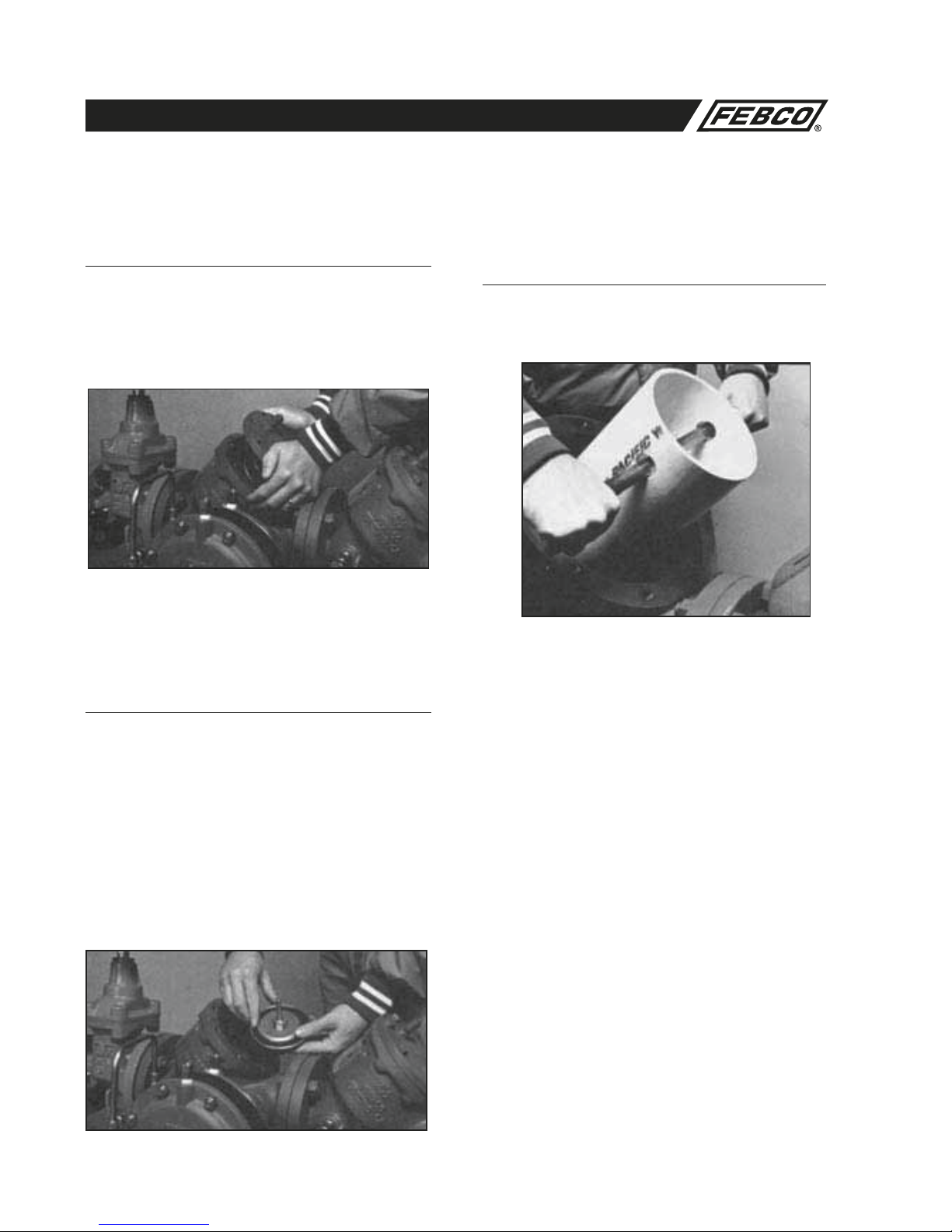
Field Testing Procedures
Purpose of Test
To test the operation of the DIFFERENTIAL PRESSURE RELIEF
VALVE and CHECK VALVE.
Equipment Required for Test
Differential Pressure Gauge test kit. Equal to the RPTK1 (shown
on page 13).
Test Differential Relief Valve
The Differential relief valve must operate to keep the zone
between the two check valves at least 2 psi less than the supply
pressure.
1. Slowly close the outlet shut-off on the discharge side of the
backflow preventer.
2. Open air bleeds and test cocks until all air from the check
valves is released.
3. Connect the “high” side of the differential pressure gauge to
test cock #2 and the “low” side to
test cock #3.
4. Open test cock #2 and test cock #3 and bleed all air from the
hose and gauge.
5. Slowly open the bypass valve needle #1 until the differential
gauge needle starts to drop. Hold the bypass in this position
and observe the reading on the gauge at the moment the first
discharge is noted from the relief valve. The differential pres-
sure at the time the relief valve opens must be no lower than
2 psi.
6. Close the bypass needle valve.
Test Check Valve 1
The check valve must be at least 3 psi more than the relief valve
opening pressure.
1. Open test cock #4 to flow a small amount of water through
the unit to restore normal pressures.
2. Observe the differential gauge with bypass valve #1 closed
and test cock #2 and #3 open. The gauge should remain at
a reading of at least 3 PSI above the relief valve. If it drops
below this, the check valve is leaking and must be serviced.
Test Check Valve 2
The check valve must be tight against reverse flow under all pres-
sure differentials.
1. Connect the “high” side of the differential pressure gauge to
test cock #4 (3rd hose).
2. Open test cock #4. With bypass needle valve #1 closed and
bypass valve #2 open, observe gauge reading. The differential
pressure should not drop to the relief valve opening point.
Restore Operation
1. Restore all valves and test cocks to their original positions.
Open and close resilient seated shut-offs slowly to prevent
damage to the system and assembly.
Figure No. 7 Figure No. 8
Differential Pressure
Gauge
Bypass
Needle
Valve #1
Test Cock
#2
Inlet
Shutoff
Value Check Valve #1 Check Valve #2
Bypass Valve #2
Test
Cock
#3
Outlet
Shutoff
Value
Test Cock #4
Relief
Valve
FEBCO Model 825YD (21/2–10")
Reduced Pressure Assembly
FEBCO Model 825Y (¾–2")
Reduced Pressure Assembly
Test Cock #4
Bypass Valve #2
Differential
Pressure Gauge
Bypass Needle Valve #1
Test Cock #2 Test Cock #3
Test Cock #1
Inlet Shutoff
Value Outlet Shutoff Value
Check
Valve #1 Check Valve #2
Test
Cock #1

10
MAINTENANCE MANUAL MODELS 825Y, 825YA, 825, 825D, 825YD & 826YD
Field Testing Procedures (Continued)
Restore Operation
After testing restore all valves to their original positions.
Note: This is a suggested typical test method. Check with your
local code for approved test procedures in your area.
Testing with the FEBCO Test Kit
The FEBCO Test Kit includes gauge, complete with hoses, fit-
tings, adapters and laminated instructions in a compact plastic
case. The FEBCO Test Kit includes a differential pressure gauge
used to test all approved Reduced Pressure Assemblies including
the FEBCO Models 825Y, 825YA, 825YD Reduced Pressure
Assemblies and the 826YD Reduced Pressure
Detector Check.
Figure No. 9
FEBCO Model 826YD (2½–10")
Reduced Pressure Assembly Figure No. 10
Test for the 826YD
This device is tested with the same procedure as the Model
825YD. However, the bypass 825Y 3/4" valve must be isolated
from the mainline valve using the 3/4" ball valves during the test
and tested separately.
Proper Bypass Operations
Flow 3 GPM through the bypass by opening the mainline test
cock #4. Use the flow meter for this measurement (1 gallon flow
in a 20 second time period). After the flow rate has been set, col-
lect the discharge flow in a container for 20 seconds. The volume
of water collected should be one gallon.
11
MAINTENANCE MANUAL MODELS 825Y, 825YA, 825, 825D, 825YD & 826YD
Service Procedure 825Y and YA (3/4–2")
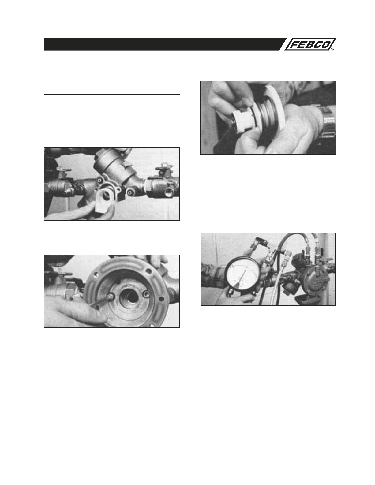
2. Check Valve Seat Replacement Model 825Y
(3/4–2") (See Figure No. 11)
a. Hold disc holder assembly in one hand and
remove screw and disc washer.
CAUTION: The use of pliers or other tools may damage the
guiding surfaces and require unnecessary replacement. Do not
scratch or mark sealing or guiding surfaces.
b. Inspect seat disc for wear or cuts remove old seat disc and
install new, or turn used disc over if new seat disc is not
available.
NOTE: The seat discs are symmetrical. It is usually possible to
turn the disc over and obtain an effective seal.
c. If the seat disc has been severely cut along the seat ring
diameter, the assembly is being subjected to extremely
high back pressure from thermal water expansion, water
hammer or other causes of excessive water pressure. Seat
discs damaged in such a manner should be replaced and not
turned over to be reused.
3. Check Valve Reassembly Model 825Y (3/4–2")
(See Figure No. 11)
a. Position the disc in the cleaned holder and retain with disc
washer and screw. CAUTION: DO NOT OVERTIGHTEN
SCREW, SECURE WITH APPROXIMATELY 12 INCH-LBS.
b. Position the spring around the centering ring of the disc
holder and reinsert the disc holder assembly into the check
body.
NOTE: Ensure the heavy check spring is installed in the No. 1
check valve or the valve will not operate properly and a con-
tinuous discharge may occur.
c. Apply a thin coating of FDA approved lubricant on the o-ring
in the cap and thread cap onto the check valve body using
the appropriate sized wrench.
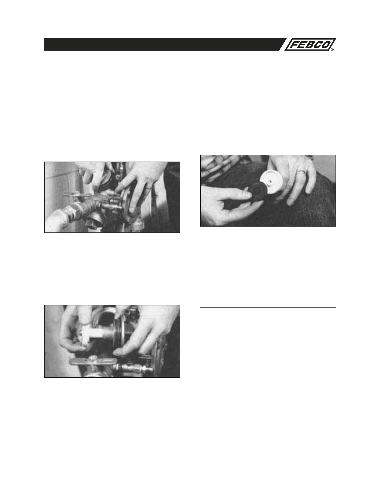
1. Check Valve Inspection/Repair Model 825Y
(¾–2") (See Figure No. 11)
a. Close inlet and outlet shut-off valves. Bleed residual pres-
sure by opening first the #4 test cock, then the #3 and #2
test cocks. See Figure No. 7 for test cock locations
b. Unscrew Cap using appropriate size wrench.
CAUTION: Cap is spring loaded. First check spring force on
3/4" to 11/2" is 10 lb. First check spring force on 11/2" to 2" is
28 lb. Retain cap with appropriate amount of hand force to
avoid injury. Second check spring force is approximately 1/4of
the first check spring.
c. Remove the spring and disc holder assembly.
d. Inspect guiding bore of the cap and poppet stem for any
buildup of calcium or other mineral deposits. If this condition
exists, it may be removed with the careful use of an appro-
priate size reamer or a thin blade knife. 3/4–11/4" cap —5/8"
(.6250) reamer 11/2–2" cap—7/8" (.8750) reamer.
e. Check disc holder and stem movement in the guide to
ensure they move freely. Debris can inhibit proper move-
ment.

12
MAINTENANCE MANUAL MODELS 825Y, 825YA, 825, 825D, 825YD & 826YD
5. Relief Valve Seat Removal Model 825Y
(3/4–2")
Standard only on units manufactured after October of 1988 with
serial numbers higher than listed below. See Figure No. 11 for
exploded view of this relief valve.
Serial #‘s of new Model 825Y
with replaceable valve seat ring:
1/4" Serial No. S6528 and above
1" Serial No. S6163 and above
1
1/2" Serial No. S5710 and above
2" Serial No. S5089 and above
a. While relief valve is disassembled, remove the two Allen
head socket capscrews using the appropriate sized Allen
head wrench. (3/16" Allen head wrench for 3/4" and 1" assem-
blies, and 1/4" Allen head wrench for 11/2" and 2" assemblies.)
b. Pull the relief valve body from the main valve body. Pull the
discharge shield from the seat ring
c. Remove seat ring with the appropriate sized socket or
needle nose pliers. Use care to avoid damage to the seat
edge. Replaceable relief valve seat is standard only on units
manufactured after October of 1988.
d. Inspect seat ring, o-rings, bushings, and gasket seals for
damage. Rinse all parts with clean water before reassembly.
d. Close the #4, #3, and #2 test cocks and slowly open first
the inlet and then outlet shutoff valves and return the
assembly to service. See Figure No. 7 for test cock loca-
tions.
e. Test the assembly to ensure it is operating properly.
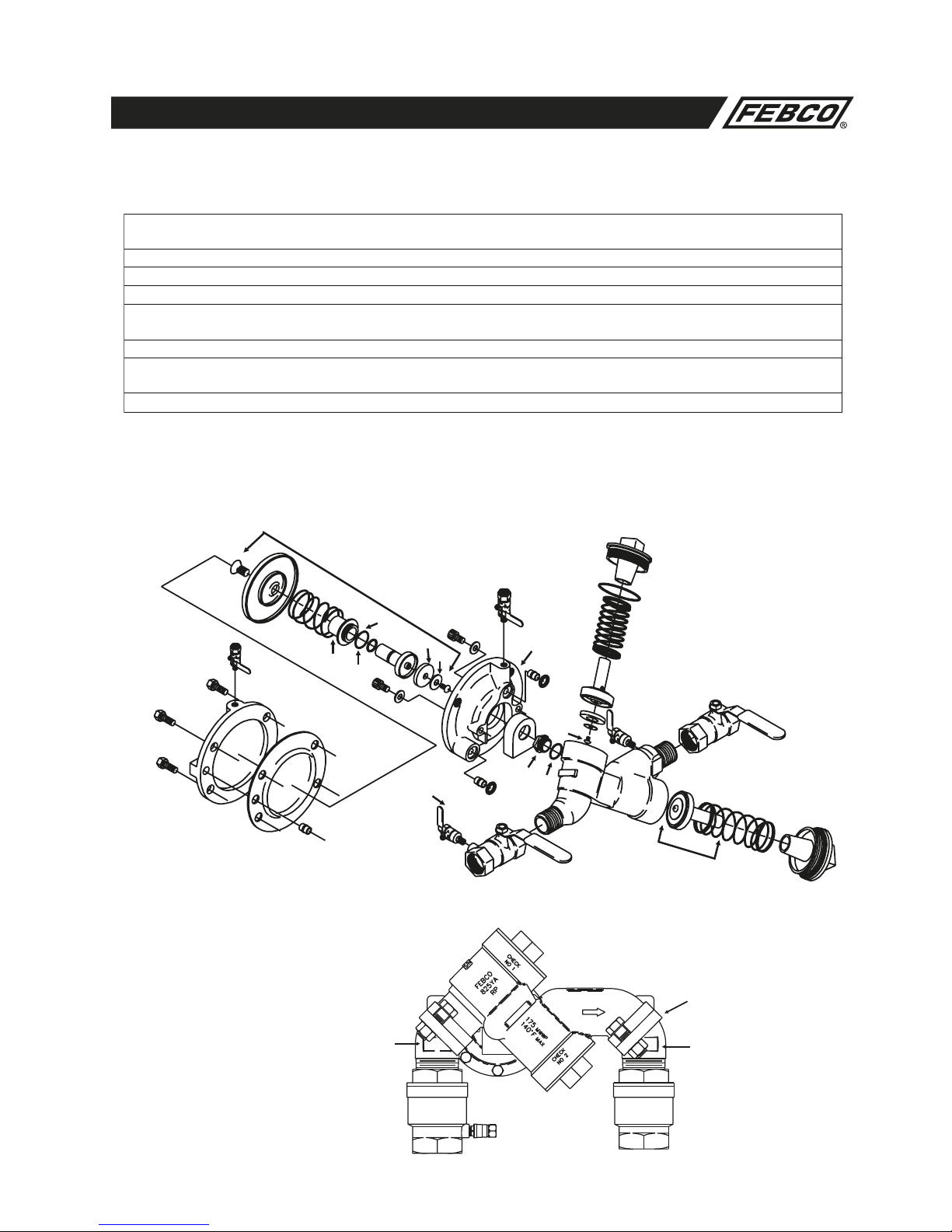
4. Relief Valve Inspection/Repair Model 825Y
(3/4–2") (See Figure No. 11)
a. Slowly close the inlet and outlet shutoff valves and bleed off
the residual pressure by opening first test cocks # 4, then #
3 and # 2. See Figure No. 7 for test cock locations.
b. Remove capscrews, diaphragm cover, diaphragm and port
bushing of relief valve.
c. Remove the integral relief valve assembly by pulling straight
out of the body to remove the internal assembly.
d. Remove the disc washer and seat disc by unthreading the
screw.
e. To remove spring and/or main stem from the guide, keep
unit compressed and remove the screw (item 18) located in
the center of the button. Push the main stem through the
guide and remove the o-ring from the main stem. Inspect
and clean or replace o-ring and seat disc as required. Clean
all parts thoroughly with clean water before reassembly.
Service Procedure 825Y and YA (3/4–2") (Continued)
13
MAINTENANCE MANUAL MODELS 825Y, 825YA, 825, 825D, 825YD & 826YD
6. Relief Valve Reassembly Model 825Y (3/4–2")
(See Figure No. 11)
a. Lubricate the seat ring o-ring with FDA approved lubricant
and thread seat ring into the valve body until seated. Do not
over tighten. (Replaceable relief valve seat ring standard on
units manufactured after October of 1988.)
b. Position the discharge shield over the seat ring diameter
and, taking care not to damage the two flow passages, rein-
stall o-rings and guide bushings.
c. Carefully place the relief valve body over the bushing and
tighten the two capscrews to retain the relief valve body to
the main valve body. New capscrew sealing washers should
be installed to avoid leakage.
d. Lubricate the o-rings and main stem using FDA approved
lubricant. Place the main stem and spring into the guide and
replace the flat head screw located at the center button.
e. Place the disc washer and seat disc in position and retain
with machine screw. Depress the diaphragm button to
ensure it is free moving.
f. Place the relief valve module into the relief valve body and
mount the diaphragm. Be careful to position the diaphragm
over the port bushing. Replace the relief valve cover and
tighten the capscrews.
g. After completing reassembly by, slowly open the inlet shut-
off valve. Then bleed air from each chamber and from the
relief valve cover by opening test cocks # 4, # 3, and # 2.
See Figure No. 7 for test cock locations. Slowly open outlet
shut-off valve and return the valve to service.
h. Test the assembly to ensure it is operating properly.
Service Procedure 825Y and YA (3/4–2") (Cont.)

14
MAINTENANCE MANUAL MODELS 825Y, 825YA, 825, 825D, 825YD & 826YD
ITEM
NO. DESCRIPTION QTY.* SIZE
¾"
SIZE
1"
SIZE
1¼"
SIZE
1½"
SIZE
2"
29 Ball Valve (Inlet) 1 781-053 781-054 781-055 781-056 781-057
29A Ball Valve (Outlet) 1 781-048 781-049 781-050 781-051 781-052
30 Testcock 4 781-074 781-074 781-075 781-075 781-075
Shutoffs: Model 825Y & YA
ITEM
NO. DESCRIPTION QTY.* SIZE
¾"
SIZE
1"
SIZE
1¼"
SIZE
1½"
SIZE
2"
3 Bushing 3 500-290 500-290 500-290 500-290 500-290
4 O-ring 2 398-202-72 398-202-72 398-202-72 398-202-72 398-202-72
5 Gasket 2 340-078 340-078 340-078 340-079 340-079
6 Capscrew 2 515-513-05 515-513-05 515-513-05 515-514-06 515-514-06
7Cap 2 101-134 101-134 101-134 101-135 101-135
8 O-ring 2 398-226-72 398-226-72 398-226-72 398-235-72 398-235-72
9 Disc Holder 2 500-270 500-270 500-270 500-278 500-278
10 Seat Disc 2 400-099 400-099 400-099 400-103 400-103
11 Washer2 300-084 300-084 300-084 300-108 300-108
12 Screw 2 516-543-03 516-543-03 516-543-03 516-543-03 516-543-03
13 Spring (Inlet) 1 630-125 630-125 630-125 630-137 630-137
14 Spring (Outlet) 1 630-115 630-115 630-115 630-118 630-118
15 Bolt 4 511-514-06 511-514-06 511-514-06 ----- -----
15 Bolt 8 ----- ----- ----- 511-515-07 511-515-07
16 Cover 1 101-029 101-029 101-046 101-035 101-035
17 Diaphragm 1 400-101 400-101 400-101 400-104 400-104
18 Screw 1 700-107 700-107 700-107 519-513-03 519-513-03
19 Button1 500-284 500-284 500-284 300-107 300-107
20 Spring 1 630-126 630-126 630-126 630-138 630-138
21 Mainstem 1 500-273 500-273 500-273 500-280 500-280
22 O-ring 1 398-113-72 398-113-72 398-113-72 398-120-72 398-120-72
23 Guide 1 500-277 500-277 500-277 500-281 500-281
24 O-ring 1 398-022-72 398-022-72 398-022-72 398-127-72 398-127-7
2
25 Seat Disc 1 400-102 400-102 400-102 400-105 400-105
26 Washer1 300-104 300-104 300-104 300-105 300-105
27 Screw 1 700-137 700-137 700-137 519-513-03 519-513-03
101 Seat Ring (Relief Valve) 1 200-779 200-779 ----- 200-780 200-780
102 O-ring (Relief Valve) 1 398-019-72 398-019-72 ----- 398-026-72 398-026-72
103 Elbow (YA only) 2 101-194 101-195 ----- 101-189 101-190
104 O-ring (YA only) 2 398-223-72 398-223-72 ----- 398-230-72 398-230-72
Model 825Y & YA Part Numbers (Sizes ¾–2”)
Model 825Y and YA (3/4–2") Parts
* Quantity required per valve.
* Quantity required per valve.
15
MAINTENANCE MANUAL MODELS 825Y, 825YA, 825, 825D, 825YD & 826YD
DESCRIPTION QTY. * SIZE
3
/
4
"
SIZE
1"
SIZE
1
1
/
4
"
SIZE
1
1
/
2
"
SIZE
2"
Check Valve Rubber Kit (2 ea. 8, 10) 1 Kit 905-042 905-042 905-042 905-053 905-053
Relief Valve Rubber ( 1 ea. 17, 22, 24, 25) 1 Kit 905-043 905-043 905-043 905-054 905-054
825YR Seat Ring Repair Kit (35, 36) 1 Kit 905-280 905-280 ----- 905-281 905-281
Check Valve Assembly (1 ea. 8, 9, 10, 11, 12) 2 Assy. 905-044 905-044 905-044 905-055 905-055
Relief Valve Assembly (1 ea. 17, 18, 19, 20, 21, 22, 23,
24, 25, 26, 27) 1 Assy.905-045 905-045 905-045 905-056 905-056
RV Seat Ring Kit (101, 102) 1 Kit 905-1
13 905-113 ----- 905-1
14 905-1
14
Complete Rubber Parts Kit (3, 4, 5, 8, 10, 17, 22, 24,
25, 102) 1 Ki
t905-111 905-111 905-111 905-112 905-112
Assemblies / Kits: Model 825Y & YA
Model 825YA (3/4–2")
Figure No. 12
Model 825Y, 825YR and YA (3/4–2") Parts (Cont.)
103
104 (O-ring)
103
* Quantity required per valve.
Model 825Y (3/4–2")
Figure No. 11
* Denotes Commercial Parts Available (see pages 31-33).
Unit is shown with ball valve shutoffs.
Some parts are sold in kits only. Consult Parts Price List for specifics.
16
15*
20
102
101
30* 4
24*
17
22
19
25
26
23
21
18*
29
Washer
3
Relief Valve Body
30*
6
4
Discharge
Shield 10
12
7
8*
13
9
8*
1
Check Assembly
29A
14
7
11
6
27
Relief Valve Assembly
16
MAINTENANCE MANUAL MODELS 825Y, 825YA, 825, 825D, 825YD & 826YD
Service Procedures 825, 825D, 825YD and 826YD
(21/2–3")
3a. Valve Seat Removal (Sizes 2½–3")
Threaded-in Seat Ring Type Models
Model 825 (See Figure No. 13)
1. Remove seat ring by un-threading in counterclockwise
direction being careful not to damage the internal epoxy
coating in valve. A tool to aid in this process is described in
Figure No. 21 on page 30.
2. Remove bushing and bushing nut (item 2A & 2B).
3. Remove o-ring.
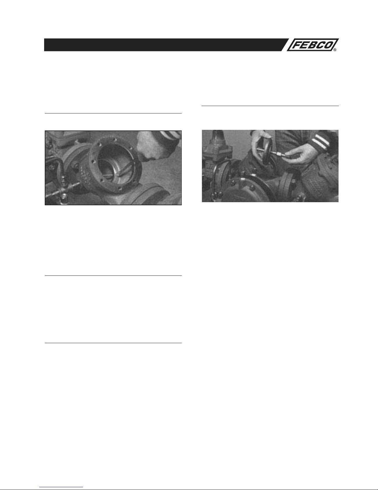
1. Check Valve Disassembly Models 825, 825D
and 825YD (Sizes 21/2–3") (See Figure No. 13)
a. Slowly close outlet shutoff valve and inlet shutoff valve.
Bleed residual pressure by opening #4, #3 and # 2 test
cocks. See Figure No. 8 for test cock location.
b. Remove cover bolts uniformly while holding cover in place.
Remove cover.
CAUTION: Spring is retained in body by cover.
c. Lift check assembly from body being careful not to damage
internal epoxy coating.
d. If necessary, un-thread bushing (item 4A) from cover.
2. Check Assembly Repair Models 825 825D
and 825YD (Sizes 21/2–3") (See Figures
No. 15 & 16)
a. Un-thread nut on stem and remove disc washer and seat
disc.
b. Inspect seat disc for wear or damage. Replace with new
seat disc or turn used disc over if new disc is not available.
NOTE: The discs are symmetrical. It is usually possible to turn
the disc over and obtain an effective seal.
c. If the seat disc has been severely cut along the seat disc
ring diameter, the assembly is being subjected to extremely
high back pressure from thermal water expansion, water
hammer, or other causes of excessive water pressure. A
disc damaged in such a manner should be replaced and not
turned over to be reused.
17
MAINTENANCE MANUAL MODELS 825Y, 825YA, 825, 825D, 825YD & 826YD
Service Procedures 825, 825D, 825YD and 826YD
(21/2–3") (Continued)
3b. Valve Seat Removal (Sizes 2½–3") Bolted in
Seat Ring Type Models 825D & 825YD
(See Figure No. 14)
1. Remove the three capscrews and washers
retaining the seat ring.
2. Pull the seat ring from the valve body being
careful not to damage the internal epoxy coating of valve.
3. If necessary, un-thread the bushing (Item 2A) from the seat
ring.
4. Remove the o-ring.
4a. Valve Seat Reassembly (Sizes 2½–3')
Threaded-in Seat Ring Type Models
Model 825 (See Figure No. 13)
1. Lubricate o-ring with FDA approved lubricant and replace on
seat ring.
2. Reinsert bushing into seat ring center.
3. Thread seat ring into valve body in clockwise direction being
careful not to damage the internal epoxy coating of valve.
4b. Valve Seat Reassembly (Sizes 2½–3")
Bolted-in Seat Ring Type Models
Model 825D & 825YD (See Figure No. 14)
1. Lubricate o-ring with FDA approved lubricant and replace in
seat ring.
2. Thread bushing into seat ring.
3. Place the seat ring carefully into body and retain with three
capscrews and washers being careful not to damage the
internal epoxy coating of valve.
5. Check Valve Reassembly (Sizes 2½–3")
(See Figures No. 15 & 16)
a. Position the disc in the cleaned holder and retain with disc
washer. Insert stem into disc holder, replace the nut on
stem and tighten.
NOTE: On older Model 825 valves, the disc holder is sealed
to the stem with a sealant. If the seal is broken, the stem
and holder must be cleaned and new sealant applied. Newer
valves, Models 825D and 825YD, use an o-ring so a sealant is
not required.
b. Thread bushing into cover.
c. Carefully place stem of check assembly into seat ring bush-
ing. Replace spring centering diameter on the disc washer.
NOTE: Be sure the heavier spring (6 psi) is placed in first check
and lighter spring (2 psi) is placed in second check or the unit
will not operate properly and discharge from the relief valve
could occur. The wire diameter is visibly thicker on the heavier
spring and thinner on the lighter spring. Care should be taken
to avoid damaging internal epoxy coating of valve.
d. Place cover on check body securing spring and stem into
cover.
e. Bolt cover onto check body while holding cover in place
with appropriate hand force. Spring will be retained in body
by cover.
f. Slowly open inlet shutoff valve. Bleed air from valve by
opening first the # 4 test cock, then the
# 3, # 2 and # 1 test cocks and air bleeds on all
covers. See Figure No. 8 for test cock locations.
g. Slowly open outlet shutoff valve and return the valve to ser-
vice.
h. Test the assembly to ensure it is operating properly.
18
MAINTENANCE MANUAL MODELS 825Y, 825YA, 825, 825D, 825YD & 826YD
Service Procedures 825, 825D and 825YD (4–10")
b. Inspect seat disc for wear or damage. Replace with new
seat disc or turn used disc over if new disc is not available.
NOTE: The discs are symmetrical. It is usually possible to turn
the disc over and obtain an effective seal.
c. If the seat disc has been severely cut along the seat disc
ring diameter, the assembly is being subjected to extremely
high back pressure from thermal water expansion, water
hammer, or other causes of excessive water pressure. A
seat disc damaged in this manner should be replaced and
not turned over for reuse.
d. Remove disc holder from stem.
NOTE: On older Model 825 valves, the disc holder is sealed
to the stem with a sealant. If the seal is broken, the stem
and holder must be cleaned and new sealant applied. Newer
valves, Models 825D and 825YD use an o-ring so a sealant is
not required.
3. Spring Removal (Sizes 4–10")
(See Figures No. 15 & 16)
CAUTION: TO AVOID POSSIBLE INJURY, DO NOT ATTEMPT
TO REMOVE SPRING TENSION WITHOUT THE USE OF
THE SPRING REMOVAL TOOL SHOWN IN FIGURE NO.
20 ON PAGE 30. ON OLDER MODEL 825 VALVES, IT IS
NECESSARY TO REMOVE THE SPRING BEFORE THE
RUBBER SEAT DISC CAN BE REMOVED.
a. Leave check assembly in body.
b. Install long studs in body 180 degrees apart.
c. Place spring removal tool over stud and retain with nuts.
(See Figure No. 20 for dimensions.)
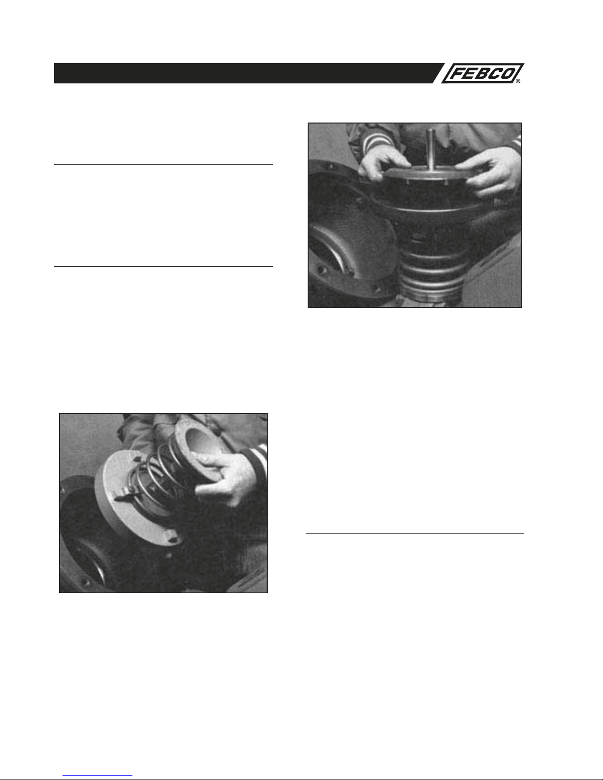
1. Check Valve Disassembly (Sizes 4–10")
(See Figures No. 15 & 16)
a. Slowly close outlet gate valve then slowly close inlet gate
valve. Bleed residual pressure by opening first the #4 test
cock, then #3, and #2 test cocks. See Figure No. 8 for test
cock locations.
b. Remove cover bolts and cover. Unscrew bolts uniformly to
avoid binding of the cover. The spring will push the cover
approximately 1/2inch off the top of the valve body.
2. Seat Disc Removal (Sizes 4–10')
CAUTION: The newer model 825 cast iron units have
threaded disc holders with four (4) cast lugs, (6 lugs on 10"
assemblies), 1/2" high located on back side, outside the spring
diameter. If the Model 825 you are servicing does not have
these lugs, SPRING TENSION MUST BE RELEASED BY
USING THE SPRING REMOVAL TOOL BEFORE FURTHER
DISASSEMBLY. DO NOT ATTEMPT TO REMOVE SPRING
TENSION ON OLDER MODEL 825s WITHOUT THE USE
OF THIS TOOL. SEE SPRING REMOVAL INSTRUCTIONS.
Newer Models 825, 825D and 825YD assemblies have the
disc holder threaded on the stem. Therefore, the seat disc can
be removed without releasing spring tension on these newer
models.
a. Un-thread retaining nut from stem and remove disc washer
and seat disc.

19
MAINTENANCE MANUAL MODELS 825Y, 825YA, 825, 825D, 825YD & 826YD
d. Un-thread capscrew (Item 7A) using 9/16" hex socket.
e. Release spring tension by un-threading nuts on long studs.
Use alternating turns to keep tool parallel to valve body.
f. Remove spring guide and stem assembly.
g. Remove guide bushing by un-threading.
4a. Valve Seat Removal (Sizes 4–10")
Threaded-in Seat Ring Type Model 825
(See Figure No. 13)
1. Remove check valve as described above.
2. Remove seat ring by un-threading in the counterclockwise
direction. For ease of removal, Figure No. 21 on page 30
defines a simple tool for this purpose.
3. Remove bushing and bushing nut if used (bushing and nut
is used on older Model 825).
4. Remove o-ring.
4b. Valve Seat Removal (Sizes 4–10") Bolted
in Seat Ring Type Model 825D and 825YD
(See Figure No. 14)
1. Remove check valve as described above.
2. Remove the three capscrews and washers
retaining the seat ring.
3. Pull the seat ring from the valve body.
4. Un-thread the bushing (Item 2A) from the
seat ring.
5. Remove the o-ring.
5a. Valve Seat Reassembly (Sizes 4–10")
Threaded-in Seat Ring Type Models
Model 825 (See Figure No. 13)
1. Lubricate o-ring with FDA approved lubricant. Reposition the
o-ring in the seat ring groove.
2. Replace the bushing and bushing nut (if used) in the seat
ring (the bushing and nut is used on older Model 825).
3. Thread the seat ring into the seating area in a clockwise
direction. Be careful not to damage internal epoxy coated
surfaces.
5b. Valve Seat Reassembly (Sizes 4–10")
Bolted-in Seat Ring Type Models
Model 825D and 825YD
(See Figure No. 14)
1. Lubricate o-ring with FDA approved lubricant. Reposition the
o-ring in the seat ring groove.
2. Thread the bushing into the seat ring.
3. Place the seat ring carefully into the valve body and retain
with three capscrews and washers being careful not to
damage the internal expoxy coated surfaces.
6. Check Valve Reassembly
Models 825, 825D and 825YD
a. Use reverse procedure for assembly.
b. Make sure the o-ring is properly placed in the groove. Do
not force the cover into the body.
c. Do not damage epoxy coated surfaces.
d. Test unit to ensure proper operation.
Service Procedures 825, 825D and 825YD (4–10") (Continued)

20
MAINTENANCE MANUAL MODELS 825Y, 825YA, 825, 825D, 825YD & 826YD
ITEM
NO. DESCRIPTION QTY.* SIZE
2½"
SIZE
3"
SIZE
4"
SIZE
6"
SIZE
8"
SIZE
10"
42 Resilient Sealed NRS (Inlet) 2 781-005 781-006 781-007 781-008 781-009 781-010
42 Resilient Sealed OS&Y (Inlet) 2 780-891 780-893 780-895 780-897 780-899 780-901
42A Resilient Sealed NRS (Outlet) 2 781-011 781-012 781-013 781-014 781-015 781-016
42A Resilient Sealed OS&Y (Outlet) 2 780-890 780-892 780-894 780-896 780-898 780-900
Shutoffs: Model 825
ITEM
NO. DESCRIPTION QTY.* SIZE
2½"
SIZE
3"
SIZE
4"
SIZE
6"
SIZE
8"
SIZE
10"
2 Seat Ring 2 780-273 780-274 780-275 780-276 780-277 780-278
2A Bushing 2 780-280 780-280 780-281 780-281 780-282 780-282
3 Guide 2 ----- ----- 190-001 190-002 190-003 190-004
4 Cover 2 780-306 780-307 780-308 780-309 780-310 780-311
4A Bushing 2 780-312 780-312 780-313 780-313 780-313 780-313
5 Disc Holder 2 190-013 190-014 190-005 190-006 190-007 190-008
6 Disc Washer 2 190-016 190-017 190-009 190-010 190-011 190-012
7 Stem 2 780-332 780-333 780-334 780-335 780-336 780-337
7A Screw 2 ----- ----- 511-515-08 511-515-08 511-515-08 511-515-08
7B Washer 2 ----- ----- 780-338 780-338 780-338 780-338
9 Spring (Outlet) 780-341 780-342 780-343 780-344 780-345 780-346
10 Spring (Inlet) 780-349 780-350 780-351 780-352 780-353 780-354
11 Seat Disc2 780-357 780-358 780-359 780-360 780-361 780-362
12 O-ring 2 398-238-72 398-246-72 398-254-72 398-264-72 398-273-72 780-095
13 Capscrew 16 511-516-08 511-516-08 511-517-08 511-519-12 511-520-12
13 Capscrew 24 ----- ----- ----- ----- ----- 511-520-14
14 O-ring 2 398-244-72 398-252-72 398-263-72 398-272-72 398-451-72 740-102
15 Locknut 2 521-547-00 521-547-00 521-550-00 521-550-00 521-551-00 521-551-00
16 Gasket 3 780-365 780-366 780-367 780-368 780-369 780-370
17 Bolt12 511-019-18 511-019-20 ----- ----- ----- -----
17 Bolt24 ----- ----- 521-019-22 521-020-26 521-020-28 -----
17 Bolt36 ----- ----- ----- ----- ----- 511-021-30
17A Nut 12 521-019-00 521-019-00 ----- ----- ----- -----
17A Nut 24 ----- ----- 521-019-00 521-020-00 521-020-00 -----
17A Nut 36 ----- ----- ----- ----- ----- 521-021-00
40 Plug Cock4 781-047 781-047 781-047 781-048 781-048 781-048
41 Nipple4 571-181-44 571-181-44 571-181-44 571-181-55 571-181-55 571-181-55
50 Air Bleed 4 9594A110 9594A110 9594A110 9594A110 9594A1
10 9594A110
51 O-ring 2 398-014-72 398-014-72 398-116-72 398-116-72 398-118-72 398-118-72
121 Relief Valve Assem. 1 902-440L 902-440L 902-446L 902-446L 902-446L 902-446L
Check Valve Body: Model 825
Model 825 (21/2–10") Parts
* Quantity required per valve.
* Quantity required per valve.
Other manuals for 825YA
2
This manual suits for next models
5
Table of contents
Popular Water System manuals by other brands


Trane
Trane Axiom GEH006 manual

Marlo Incorporated
Marlo Incorporated RO-14C Installation, operation & service manual

Sterling
Sterling SGM-250A product manual

flamco
flamco Flamcomat MP G4 Remote Installation and operating instruction

Everpure
Everpure XC Filter Cartridge EV9613-09 Specification sheet

Condair
Condair RO Series Quick starting guide