Osmonics E4H Series Installation guide

E4H-SERIES
WATER PURIFICATION MACHINES
14,400 GPD TO 43,200 GPD
OPERATION AND
MAINTENANCE MANUAL
q
Permeate
Carrier
Membrane
Membrane
Backing
Adhesive
Bond

2

E4H-SERIES WATER PURIFICATION MACHINES
14, 400 GPD – 43, 200 GPD
OPERATION AND MAINTENANCE MANUAL
TABLE OF CONTENTS
Page
1.0 DESCRIPTION........................................................................................................................................... 1
1.1 General Information and Principles of Operation.................................................................. 1
1.2 Machine Nomenclature................................................................................................................. 4
1.3 Machine Permeate Quality........................................................................................................... 5
1.4 Economy (ECN) Model and Deluxe (DLX) Model Option................................................. 5
1.5 Specifications for E-Series Machines .......................................................................................... 6
2.0 INSTALLATION........................................................................................................................................ 9
2.1 Mounting........................................................................................................................................... 9
2.2 Piping ................................................................................................................................................. 9
2.3 Electrical............................................................................................................................................ 10
3.0 PREPARATION AND START-UP ........................................................................................................ 10
3.1 Pretreatment for Water Purification......................................................................................... 10
3.2 Start-Up ............................................................................................................................................ 11
4.0 OPERATION AND MAINTENANCE ................................................................................................. 15
4.1 Daily Log Sheets ............................................................................................................................. 15
4.2 Pre-Filter........................................................................................................................................... 15
4.3 Flushing.............................................................................................................................................. 16
4.4 Cleaning ............................................................................................................................................ 16
4.5 Draining Machine for Shipment................................................................................................... 18
4.6 Sepralator Installation.................................................................................................................... 18
4.7 Sepralator Replacement................................................................................................................ 20
5.0 OPTIONAL ACCESSORIES ................................................................................................................... 20
5.1 Level Controls................................................................................................................................. 20
5.2 Filters and Water Softeners ........................................................................................................ 20
5.3 Storage Tanks.................................................................................................................................. 20
6.0 TROUBLESHOOTING............................................................................................................................ 22
7.0 SPARE PARTS LIST................................................................................................................................... 25
8.0 RETURN GOODS AUTHORIZATION (RGA) PROCEDURE..................................................... 27

8.0 WARRANTY/GUARANTEE .................................................................................................................. 28
9.0 START-UP DATA ..................................................................................................................................... 29
10.0 DAILY LOG FOR E4H MACHINES..................................................................................................... 30
LIST OF FIGURES
Figure Title
1 Normal vs. Crossflow Filtration............................................................ 1
2 Membrane Sepralator with Interconnectors...................................... 2
3 Cross-Sectional View of Sepralator...................................................... 2
4 Principles of Operation............................................................................ 3
5 Typical Membrane Rejections/Passages ............................................... 8
DWG # 1159330 ECN Electrical Diagram..........................................................Attached
DWG # 1163858 ECN Flow Diagram..................................................................Attached
LIST OF TABLES
Table Title
1 Machine Recovery..................................................................................... 14
2 Dry Chemical Cleaners ........................................................................... 17

1.0 DESCRIPTION
1.1 General Information and Principles of Operation
Your E-Series reverse osmosis (RO) machine is a durable piece of equipment which, with
proper care, will last for many years. These instructions give operating and maintenance
details vital to the sustained performance of the machine.
RO is the separation of one component of a solution from another component by
means of pressures exerted on a semipermeable membrane. Removal of ionic, organic
and suspended / dissolved impurities occurs during the RO process. Unlike a filter, which
separates by “normal” filtration, the Osmo®sepralator separates using a process called
crossflow filtration. Feedwater solution is separated into two streams, permeate and
concentrate, and collected from both sides of the membrane. A semipermeable RO
membrane, under sufficient pressure, allows passage of purified water while rejecting
and concentrating dissolved and suspended solids.
Figure 1 - Normal vs. Crossflow Filtration
Osmonics manufactures a patented spiral-wound membrane package, with a turbulent flow
design. This membrane module, called a sepralator, collects the purified water within a cen-
tral tube, the permeate tube (see Figures 2 and 3).
1

Figure 2 - Membrane Sepralator with Interconnectors
Figure 3 - Cross-Sectional View of Sepralator
2

Some operating definitions are provided to help you further understand your machine:
Permeate Rate [Product Water Rate (Qp)] is the flow rate of purified water which
has passed through the membrane and out of the sepralator; expressed in gal/min (gpm) or
gal/hr (gph) [in metric, liter/min (Lpm) or cubic meters/hour (m3/h)]. Specified permeate
rates are normally at 77ºF (25ºC).
Concentrate Rate [Waste Water Rate (Qc)] is the flow rate of water containing
rejected solids to drain in gpm or gph (Lpm or m3/h).
Feed Rate (Qf)is the flow rate of incoming water in gpm or gph (Lpm or m3/h).
Feedwater rate equals permeate rate plus concentrate rate.
Recovery equals permeate rate divided by feed rate and is expressed as a percentage. For
example, 33% recovery means that out of a given feed rate, 33% is produced as purified
water (permeate).
Concentration equals the Total Dissolved Solids (TDS) concentration of a solution
expressed as milligrams per liter (mg/L) or conductivity (microSiemens/cm).
Cf = Feed Concentration
Cp= Permeate Concentration
Cc= Concentrate Concentration
Cavg = Average Concentration in Machine
Salt (Ionic) Rejection equals the percent of dissolved salt rejected by the membrane,
calculated from an average concentration over the membrane.
Salt (Ionic) Passage equals (100% - rejection) or the percent of dissolved salts passed
through the membrane.
An example of how to calculate salt rejection and recovery is given below:
Figure 4 - Principles of Operation
3

Given the system case in Figure 4:
Average Concentration (Cavg) = (Cf) 100 mg/L + (Cc) 146.9 mg/L
2
(Cavg) = 123.5 mg/L TDS
Rejection = (Cavg) 123.5 - (Cp) 6.2 x 100 = 95%
(Cavg) 123.5
Passage = (Cp) = 6.2 x 100 = 5.0%
(Cavg) 123.5
Recovery = (Qp) 2 gpm x 100 = 33%
(Qf) 6 gpm
Flow Description - The feedwater passes through a replaceable 5-micron cartridge filter
which removes bulk suspended solids. Filtered water then flows to the inlet control valve.
This solenoid-controlled diaphragm valve is wired to the on/off switch and opens when the
machine is turned on, allowing water to flow to the pump inlet. When the machine is
turned off, the valve closes, preventing non-turbulent flow through the sepralators, which
would lead to shortened membrane life.
The pump feeds water to the sepralator housings arranged in parallel and serial combina-
tions. The direction of water flow is indicated by an arrow on each sepralator housing.
Water is separated by the membrane within the sepralators and leaves the sepralator hous-
ings in two streams: permeate and concentrate.
Permeate from each sepralator housing is collected in a common manifold. The permeate
then flows through a flow meter and to the outlet point of the machine.
The concentrate leaves the last sepralator housing and flows to the flow control center
(recycle/concentrate manifold). At this point, the recycle valve channels a predetermined
amount of concentrate into the pump inlet. Recycle increases recovery while maintaining
adequate crossflow through the sepralators. The other two ports of the flow control cen-
ter lead to the concentrate valve and final pressure gauge. The concentrate valve has three
functions: It controls the amount of concentrate flowing to the drain; it controls the pres-
sure within the machine; and it helps control the system recovery. An autoflush solenoid is
added to the flow control center with an additional tee. The concentrate then flows
through a flow meter and to the outlet point of the machine.
1.2 Machine Nomenclature
E-Series water purification machines are numbered in such a way as to indicate the perme-
ate flow and quality you can expect from the machine:
Example: E4H-21K/ECN, 230, 6, 50-75
• E4H indicates the machine series
• H indicates horizontal membrane element housing configuration
4

• 21K indicates the rated permeate flow in thousands of gallons per day @
77ºF (25ºC), i.e., 21K = 21,000 gallons per day
• ECN indicates Economy Model and DLX indicates the Deluxe Model
• 230 indicates 230 VAC, three-phase voltage to starter
• 6 indicates 60 Hz operation, whereas 5 indicates 50 Hz operation
• 50 - 75 indicates 50% to 75% recovery
1.3 Machine Permeate Quality
The permeate rejection performances are as follows:
E4H machines use high rejection Osmo 415 - HR(PA) membrane elements, providing the
ultimate in high purity water.
1.4 Economy (ECN) Model and Deluxe (DLX) Model Option
1.4.1ECN Model
E-Series ECN model water purification machines have all the features
necessary for safe, continuous production of high purity water. This
assumes good quality feedwater, adequate pretreatment and regular operator
maintenance, each shift or daily, to the operation of the system.
• 50% to 75% recovery
• Multi-stage centrifugal pump, SS construction (stainless steel castings
with Noryl* stages)
• Base model electrical package includes NEMA-1 enclosure with a 110
VAC, 60 Hz or 220 VAC, 50 Hz single-phase control circuit; applies to all
ECN models
• Automatic inlet shutoff valve
• Pre-filter housing and 5-micron cartridge filter
• Pre-filter, post-filter, primary and final pressure gauges
• Digital concentrate and permeate flow meters
• Digital conductivity monitor, panel-mounted, for permeate quality monitor-
ing
• Autoflush System - programmable, automated high-velocity membrane
flushing for the longest membrane life; set at the factory and adjustable in
the field
* Noryl is a trademark of General Electric Company.
5

• Gauges, valves and rigid piping of stainless steel or plastic
• Sepralator housings, all 304 stainless steel, with Noryl end caps
• 316 stainless steel concentrate and recycle valves
• All components in contact with the purified water (permeate) are either
FDA-acceptable plastic (nylon, Noryl, polypropylene, PVC) or stainless
steel materials.
• All high pressure fittings are 304 stainless steel.
• Alarms included: low inlet pressure and high amp draw
1.4.2 DLX Model Option
The DLX package contains all of the above ECN standard features along
with a PLC control system.
• Multi-stage centrifugal pump, SS construction (316 stainless steel end
castings and other wetted parts, Noryl internals)
• Autoflush System - programmable, automated high-velocity membrane
flushing for the longest membrane life; set at the factory and adjustable in
the field
• All high pressure fittings are 304 stainless steel.
• Special electrical upgrade package includes PLC controller with alarm
delay shutdown for low inlet pressure condition to prevent pump damage
should pressure fall below 15 psig (1 bar)
• Clean-In-Place (CIP) system
• Digital flow meter and conductivity controller
• Digital pH controller
• Alarms included: low inlet pressure, high amp draw, high / low pH
1.5 Specifications for E-Series Machines
1.5.1 Feedwater Specifications
Temperature 35-77°F (2-25°C) [Not to exceed
85°F (29°C) unless specifically
designed for higher temperatures]
Inlet Pressure Minimum 30 psig (2.1 bar); Maximum
60 psig (4.1 bar)
Chlorine (continuous feed) For Osmo HR(PA) membranes 0 ppm
6

Operating pH For soft water [less than 1 grain per
gallon (gpg) or 17 mg/L hardness],
acceptable pH is 3.0 -10.0. For
unsoftened water (contact factory
with water analysis), acceptable pH
is 5.5 - 6.0.
Pre-Filter 5-micron Hytrex®cartridge (See
machine label for part number.)
Inlet Connections 1.5-inch FNPT
1.5.2 Permeate (Product Water) Flow Rate
Stated on the serial number label (assumes no permeate backpressure,
2000 mg/L TDS maximum feed concentration, and rated temperature)
To estimate permeate output with backpressure, use the formula below:
Permeate Flow on Label x Operating pressure - (Permeate backpressure)
Operating Pressure
Permeate Backpressure Maximum - 80 psig (5.5 bar)
Permeate Outlet 1-inch FNPT
1.5.3 Concentrate Flow Rate
Factory-set as stated on serial number label
Concentrate Outlet 1-inch FNPT
1.5.4 Typical Pure Water
Recovery: 50 - 75%
1.5.5 Operating Final Pressure: Minimum - 200 psig (13.8 bar)
Maximum - 235 psig (16.2 bar)
1.5.6 Pump
Multi-stage centrifugal; approximate primary operating pressure of 190 psig
(13.1 bar) excluding line pressure
1.5.7 RO Membrane Rejection - (See Figure 4)
Osmo HR(PA)
Typical Ionic Rejection 95 - 98%
Average Molecular Weight (MW) Cutoff * 150 MW *
* The MW cutoff is based on the pore size of the membranes and the
nature (size/shape) of the organic molecule.
7

8
SALTS
CATIONS
Percent Maximum
Percent Passage Concentration
Name Symbol Rejection (Avg) Percent
Sodium Na+94-96 5 5-10
Calcium Ca+2 96-98 3 *
Magnesium Mg+2 96-98 3 *
Potassium K+1 94-96 5 5-10
Iron Fe+2 98-99 2 *
Manganese Mn+2 98-99 2 *
Aluminum Al+3 99+ 1 10-20
Ammonium NH4+1 88-95 8 3-8
Copper Cu+2 98-99 1 10-20
Nickel Ni+2 98-99 1 10-20
Zinc Zn+2 98-99 1 10-20
Strontium Sr+2 96-99 3 -
Hardness Ca & Mg 96-98 3 *
Cadmium Cd+2 96-98 3 10-20
Silver Ag+1 94-96 5 *
Mercury Hg+2 96-98 3 -
ANIONS
Chloride Cl-1 94-95 4 5-8
Bicarbonate HCO3-1 95-96 4 5-10
Sulfate SO4-2 99+ 1 5-15
Nitrate NO3-1 85-95 10 3-6
Fluoride F-1 94-96 5 5-8
Silicate SiO2-2 80-95 10 -
Phosphate PO4-3 99+ 1 10-20
Bromide Br-1 94-96 5 5-8
Borate B4O7-2 35-70** - -
Chromate CrO4-2 90-98 6 8-12
Cyanide CN-1 90-95** - 4-12
Sulfite SO3-2 98-99 1 5-15
Thiosulfate S2O3-2 99+ 1 10-20
Ferrocyanide Fe(CN)6-3 99+ 1 10-20
ORGANICS
Maximum
Molecular Percent Concentration
Weight Rejection Percent
Sucrose Sugar 34299.9 30-35
Lactose Sugar 360 99.9 30-35
Protein 10,000 Up 99.9 50-80
Glucose 180 99.0 15-20
Phenol 94 *** -
Acetic Acid 60 *** -
Formaldehyde 30 *** -
Dyes 400 to 900 99.9 -
Biochemical
Oxygen Demand (BOD) 90.0-99.9
Chemical -
Oxygen Demand (COD) 99.9
Urea 60 40-60 Reacts similar to
a salt
Bacteria & Virus 50,000 to 99.9+
500,000 -
Pyrogen 1,000 99.9+ -
to 5,000
*** Permeate is enriched in material due to preferential passage
through the membrane.
GASES, DISSOLVED
Carbon Dioxide CO230-50%
Oxygen O2Enriched in permeate
Chlorine Cl230-70%
To estimate passage of salts for membranes other than SEPA-HR, take the
passage for the SEPA-HR and multiply by the factor for the passage for the
particular membrane. The factors are:
SEPA-SR is 1.6 times SEPA-HR passage
SEPA-PR is 2.5 times SEPA-HR passage
Operation of the SEPA-HR membrane at pressures over 400 psig (27.6 bar)
will reduce salt passage slightly. Operation at 200 psig (13.8 bar) will increase
the passage of monovalent ions by approximately 2.0 times and the passage of
multivalent ions will increase by 1.5 times the 400 psig (27.6 bar) passage.
For SEPA membranes with larger pores than the SEPA-PR it is recommended
that actual tests be run prior to estimating the permeate quality.
The maximum concentrations given in the table are the approximate
concentrations resulting in an osmotic pressure of 500 psi (34.5 bar) for the
solution.
Compounds such as CaSO4which have specific solubility limits can be
controlled with proper addition of dispersants. Check with the factory for
more information on Osmonics’ special line of dispersants.
* Must watch for precipitation; other ion controls maximum
concentration
** Extremely dependent on pH; tends to be an exception to the
rule
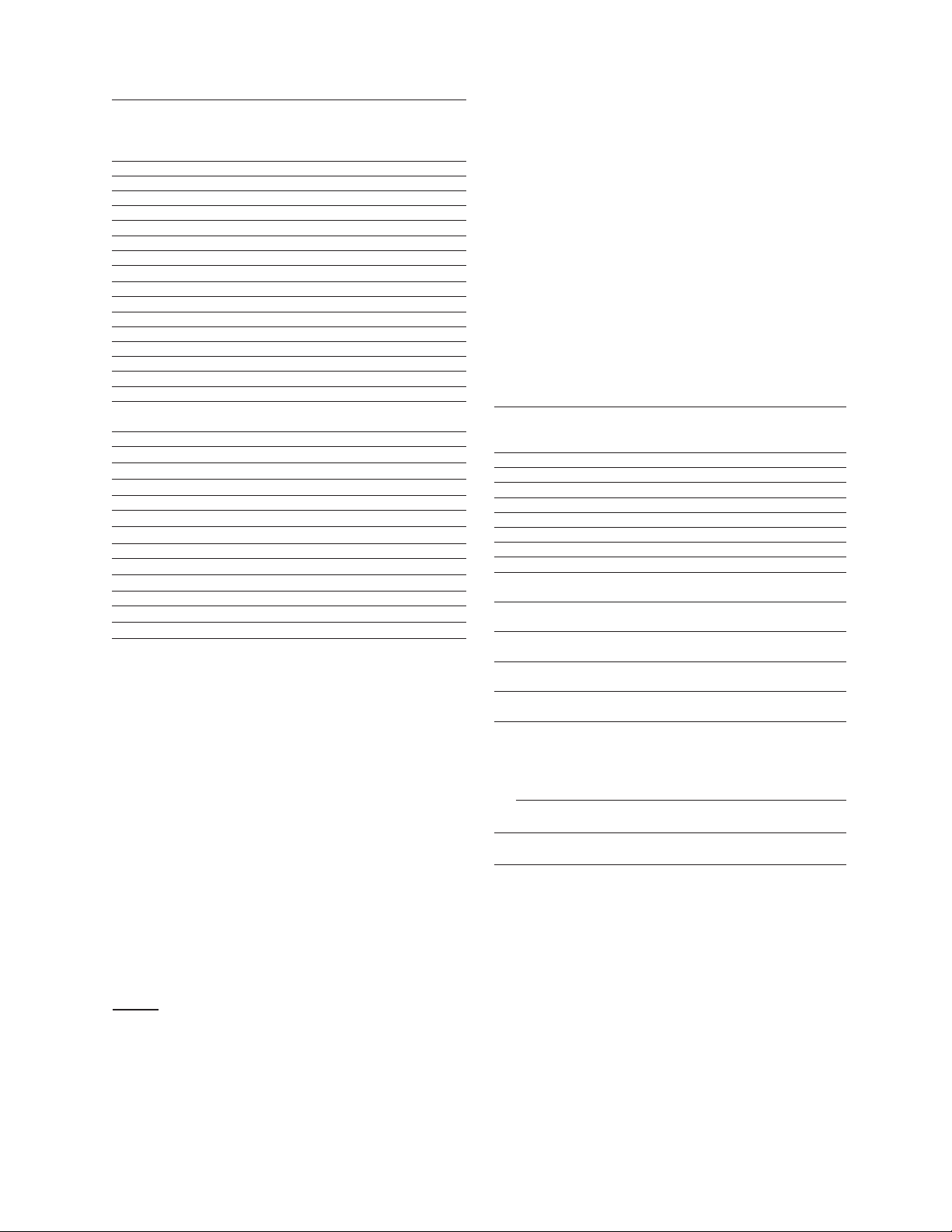
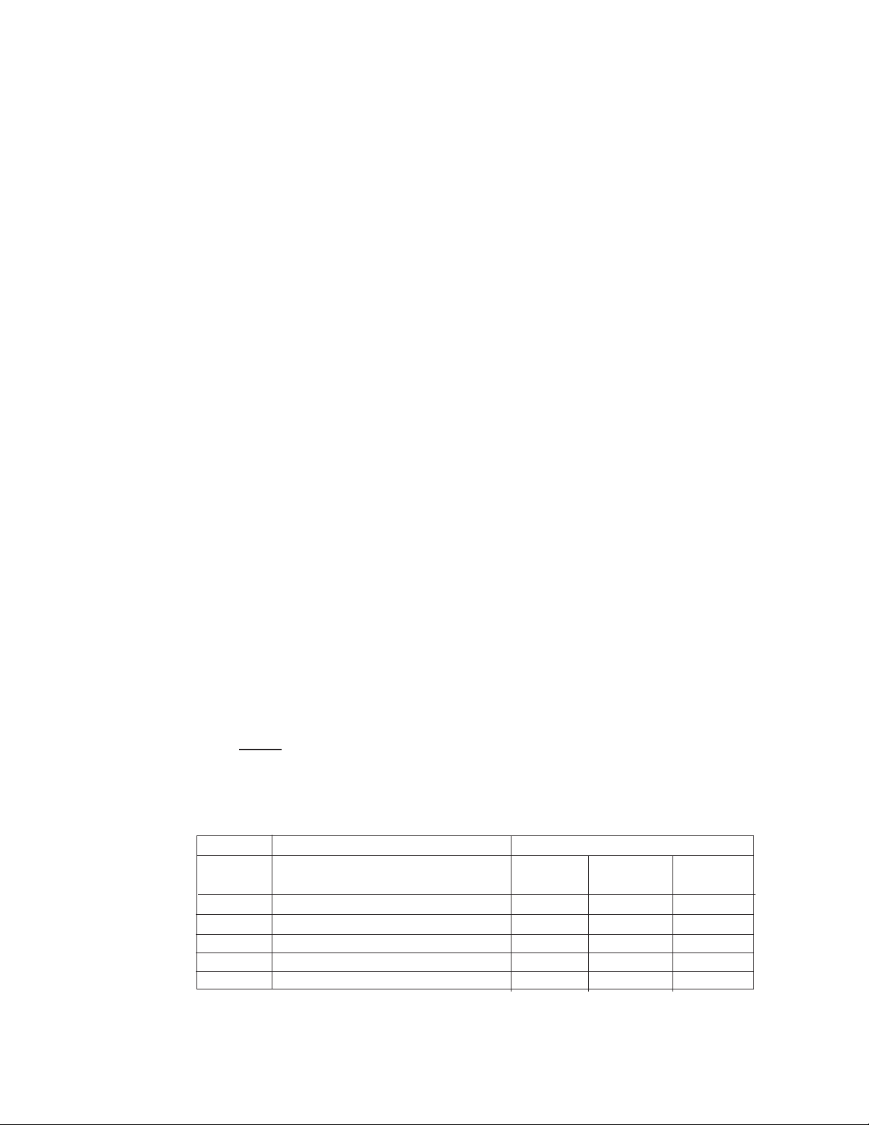
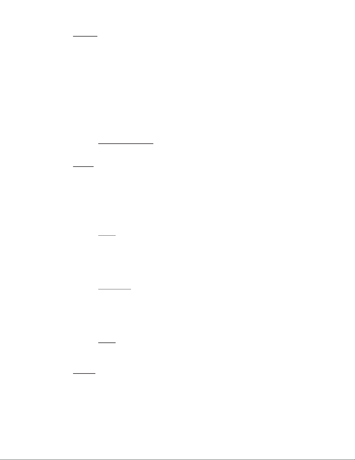
The following are typical rejections and passages for various salts and organics
using the SEPA®-HR membrane at 400 psig (27.6 bar) operating pressure.
Modules made with this membrane, such as the OSMO®-HR, can be expected
to give these same passages. As can be seen, multivalent ions tend to have
less passage than do monovalent ions. If monovalent ions are combined with
multivalent ions to form a salt, the passage will be controlled by the multiva-
lent ion. In RO all ions must be combined as the salt form before passages can
be considered.
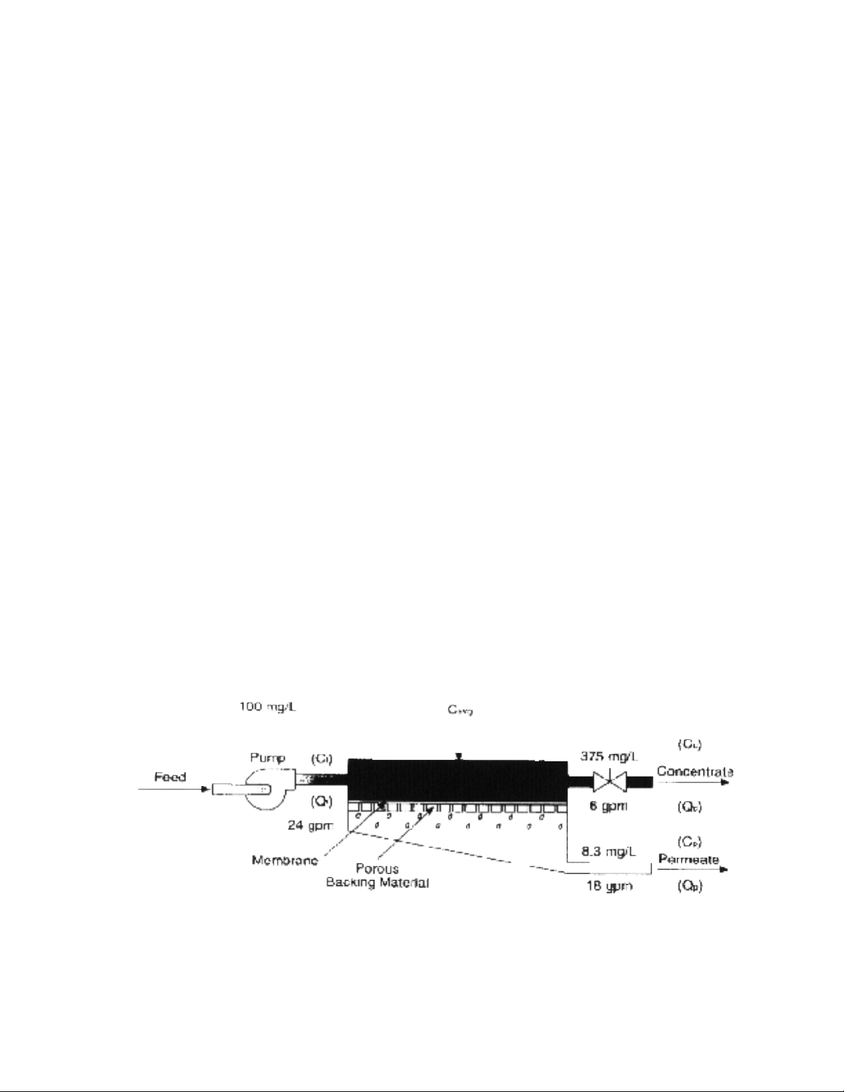
For estimating purposes, to obtain the expected permeate quality when han-
dling a solution of salts, take a simple average of the feed concentration and
the
concentrate concentration and multiply this figure by the average percent pas-
sage to calculate the average concentration of the permeate.Salts or organics
that are complexed with organics of large molecular weights will tend to act
like the organics with which they are complexed.
NOTE: The actual permeate water quality will vary with the inlet water quality and can only be veri-
fied by actual analysis of the permeate stream.
Figure 5 - Typical Membrane Rejections/Passages

2.0 INSTALLATION
2.1 Mounting
E4H machines are equipped with a stand alone frame, 61-inch (155-cm) H x 132-inch (335-
cm) W x 34-inch (86-cm) D, which supports the machine. At least 45 inches (114 cm) of
space should be allowed on each end of the sepralator housings for removal and loading of
sepralators. If 45 inches (114 cm) are not available, the entire sepralator housing may need
to be removed for sepralator changes.
2.2 Piping
2.2.1 Inlet Piping
The feedwater source is piped to the inlet using 1.5-inch NPT fittings. A CIP
system is supplied with the DLX Model E4H. FOR ECN MODEL: To install a
CIP system, remove plug and install valves on the E-Series machine as
described in Section 2.2.2. If the inlet pressure is in excess of 60 psig
(4.1bar) or fluctuates by more than 5 psig (0.4 bar), a pressure regulator should
be installed ahead of the CIP tee.
2.2.2 Valves Required for CIP, ECN Models Only
IMPORTANT NOTE: Osmonics has installed a plugged pipe tee in the inlet
line of the E4H units. This plug, when removed, will
facilitate cleaning of the unit. A tee with (two) two-way
valves or a single three-way valve should also be
installed on the permeate and concentrate outlets to
allow flow back to the cleaning tank. Never operate
the machine with the concentrate or permeate lines
blocked. Severe damage to the unit may result.
(Refer to the attached drawing # 1163858 for a
system flow schematic.)
2.2.3 Concentrate Outlet Connection
Install the CIP valve on the concentrate outlet tee, connect a 1-inch hose or
pipe, and run it to an open drain. To avoid drainage from the machine while
not in use, the concentrate outlet piping should be placed at a height at least equal
to the height of the machine. A siphon break may also be installed in the concen-
trate line for added protection. The concentrate outlet hose can be any length, and
the diameter should match the outlet on the machine. [Maximum backpressure is
60 psig (4.1 bar).]
2.2.4 Permeate Outlet Connection
Install the CIP valve on the permeate outlet tee. The pure water (permeate)
should be transported to the point of use via noncorroding-type tubing, pipe,
or hose. Examples are: food-grade flexible nylon tubing, stainless steel
tubing, or PVC hose. The permeate outlet is 1-inch FNPT.
9

2.3 Electrical
The DLX and ECN E-Series models are supplied with a single-phase, 110 VAC 60 Hz or
220 VAC 50 Hz control circuit and 8-foot cord which plugs into a three-prong
grounded receptacle. For 220 VAC, 50 Hz units, plug must be customer-supplied. A
20 amp dedicated service circuit is required for proper operation.
For each model, the motor is wired at the factory to an overload protection magnetic
motor starter which is controlled by a panel-mounted manual switch.
The electrical system control circuit is separate from the motor voltage. Therefore,
electrical wiring required in the field needs two supply voltages, the control circuit
voltage and a separate three-phase motor voltage. All field wiring must comply with
applicable local and national electric codes.
2.3.1 ECN Electrical System
2.3.1.1 Connect the control circuit power cord to 115 VAC, 60 Hz, or 220
VAC, 50 Hz, single-phase power.
2.3.1.2 Connect the magnetic motor starter 230/460 VAC or 220/380 VAC,
three-phase power to match the motor voltage and phase. Check
the tag (located on the motor starter) that indicates the factory
wiring. A separate, fused disconnect for the motor wiring is
required, with proper protection for the Hp and amp draw of the
motor.
(See attached drawing #1164309 for the ECN electrical diagram). The ECN circuit has
a timing relay for delayed machine shutdown.
2.3.2 DLX Electrical System
2.3.2.1 Connect the control circuit power cord to 115 VAC, 60 Hz, or
230 VAC, 50 Hz, single-phase power.
2.3.2.2 Connect the magnetic motor starter 230/460 VAC or 220/380 VAC,
three-phase power to match the motor voltage and phase. Check
the tag (located on the motor starter) that indicates the factory
wiring. A separate, fused disconnect for the motor wiring is
required, with proper protection for the Hp and amp draw of the
motor.
3.0 PREPARATION AND START-UP
3.1 Pretreatment for Water Purification
All systems will operate most efficiently on filtered water with a pH of less than 6.5 and a
Silt Density Index (SDI) of 5 or below. If the machine is operated on higher pH water,
other forms of pretreatment may be necessary. A water analysis prior to start-up of the
machine is required. To minimize the chances of calcium carbonate, calcium sulfate, or
10

other salt precipitation on the membrane, Osmonics evaluates each application and water
condition and makes specific recommendations to ensure continuity of the membrane
sepralator warranty. Data from the water analysis is processed with a computer program
analysis to determine if potential problems exist. If the machine is to be run at a different
location than was originally intended, a new water analysis is required for warranty consid-
eration and should be sent to Osmonics for review and recommendations for operation of
the machine.
Before entering the machine, the feedwater must be filtered to 5 microns.
TLC membrane feedwater must not contain the following chemicals or permanent loss of
rejection and/or permeate flow may result:
•free chlorine
•formalin (until after a sepralator has been run for 24 hours; thereafter, 0.5% formalde-
hyde may be used as a biocide)
•iodine compounds
•quaternary germicides
•cationic surfactants
•detergents containing non-ionic surfactants
•cleaners not approved by Osmonics
CAUTION: A water softener should not regenerate while the machine is run-
ning unless safeguards are used to be sure the machine is operat-
ed on softened water during regeneration.
3.2 Start-Up
NOTE: If your machine is provided with the sepralators installed in the housings, proceed
to 3.2.1. If your machine is provided with the sepralators in shipping boxes, you
must load the sepralators in the housings prior to starting the machine. For
sepralator loading instructions, skip to 4.6. Upon completion of sepralator instal-
lation, return to section 3.2.1 to continue your start-up procedure.
3.2.1 Re-check the function and integrity of your pretreatment equipment. Ensure
that your water softener, activated carbon filters and iron filters (where
applicable) have been leak-checked, backwashed, and thoroughly rinsed for
service before starting up your RO unit.
3.2.2 Attach the feedwater pipe to the inlet of the machine.
3.2.3 Check for leaks at all connection points.
11

3.2.4 Turn on the feedwater gradually and check for leaks in the inlet piping. No
flow should go through the machine while the power is off and the inlet sole-
noid is in the closed position.
NOTE: When the machine is off, there should never be flow through the
machine. Flow through the machine when it is off can ruin the
sepralators, and the inlet solenoid must be repaired.
3.2.5 Attach tubing from permeate and concentrate outlet points, and run the
tubing to drain.
3.2.6 Ensure that you have made provisions for both voltages required to operate
your machine. The machine requires two power sources: (1) the high volt-
age for the motor operation, and (2) the control circuit power supply. The
factory provides the 110 VAC (or 220 VAC 50 Hz) power cord needed for the
control circuit. The motor electrical service must be field-wired directly into
the motor starter on the machine. Bring your motor service to terminals
labeled “T” on the motor starter. Check the voltage label to ensure that you
have brought the correct voltage to the starter.
3.2.7 Be sure the power to the motor starter is de-energized.
3.2.8 With the machine ON/OFF switch in the OFF position, plug in the factory-
supplied 110 VAC (or 220 VAC 50 Hz) power cord.
3.2.9 Open your concentrate and recycle flow control valves two complete turns.
These valves are positioned on the flow control center of the machine. This
piping is located on the left section of the machine, near the sepralator
housings. The flow control center features a concentrate flow control valve,
a recycle flow control valve, and a pressure gauge sensor point piped into
the panel-mounted pressure gauge.
NOTE: The autoflush valve is positioned in this flow control center.
The proper adjustment of these valves is critical to the operation of the RO
machine. The concentrate valve determines the amount of rejected water
leaving the machine, and creates the operating pressure shown on the pres-
sure gauge. The recycle valve returns unused reject flow back into the inlet
stream to the RO pump. It is important to balance the operating pressure
and the respective flows of these valves to ensure that your machine is
operating correctly. It is also important to understand the relationship of
these two valves, the pressure gauge, and your RO pump. The pump has a
fixed amount of flow produced, and the valves are the control devices to dis-
tribute this fixed flow amount. The pressure gauge is an indicator of applied
membrane pressure, at the flows set by the valves.
3.2.10 Turn the ON/OFF switch to the ON position. Water will begin to flow through
the machine at this point but the pump will not start. Allow the machine to
operate in this manner for 10 minutes, to purge the air out of the machine.
Verify alarm set-points in the Lakewood 2450 Reverse Osmosis controller.
12

Consult the Lakewood Model 2450 Installation and Operation Manual (P/N
1109695) for operating instructions. The factory alarm setpoints are as
follows:
Low Inlet Pressure 12 psig
Low pH 2.0
High pH 8.0
pH Control 5.6-6.2
High Temperature 120ÞF (39ÞC)
NOTE: The high-pressure pump should not be operating at this time.
3.2.11 As your machine is filling check for leaks and repair as needed.
3.2.12 Turn the ON/OFF switch to the OFF position.
3.2.13 Energize the power source to the motor starter. The pump should not oper-
ate at this point.
3.2.14 Check the rotation of the high pressure pump by briefly turning the ON/OFF
switch to the ON position. Watch the motor, or coupling shaft, for direction
of rotation. The motor should rotate clockwise as one looks at the motor end
of the high pressure pump. If the motor is not rotating clockwise, change any
two of the three leads (for three-phase) in the motor starter and recheck
rotation. Always turn the power off to change any wiring.
CAUTION: Operation of the pump backwards for even a short time
can cause damage to the pump.
3.2.15 Turn the ON/OFF switch to the ON position. The high-pressure pump will
operate and the machine will begin to build pressure. As you are operating,
be sure to watch the pressure gauge on the instrument panel. The machine
is designed to operate at 220 psi (15.2 bar).
NOTE: Do not allow the pressure to exceed 250 psi (17.3 bar). If the pres-
sure exceeds 250 psi (17.3 bar), open the concentrate flow control
valve until the pressure gauge shows 250 psi (17.3 bar) or less.
As the machine purges the air and fills with water, the pressure will gradually
increase. You should see water flowing through the permeate and concen-
trate flow meters. If you do not see flow, turn the machine off and return to
Section 3.2.1.
NEVER ALLOW THE MACHINE TO OPERATE WITHOUT ADEQUATE
WATER PRESSURE. THIS CAN CAUSE SEVERE DAMAGE TO THE
HIGH-PRESSURE PUMP
.
3.2.16 Gradually close the concentrate flow control valve. As you close the valve,
watch the pressure gauge and your concentrate flow meter. Close the valve
until your concentrate flow meter displays your design flow, and you do not
13

exceed 250 psi (17.3 bar). If you reach 250 psi (17.3 bar) before the valve is
completely closed, open the recycle flow control valve one full turn, then
continue to close the concentrate flow control valve. Continue to close the
concentrate flow control valve until it is completely closed and your pressure
is below 250 psi (17.3 bar).
The concentrate flow control valve has a drilled orifice to ensure a predeter-
mined amount of flow and pressure in the closed position. This orifice is
sized to operate the machine at 75% recovery.
3.2.17 With the concentrate flow control valve fully closed and the pressure below
250 psi (17.3 bar), gradually close the recycle flow control valve until the
pressure reaches 250 psi (17.3 bar).
Your machine is now operating at the design pressure and flow rates, in a
75% recovery configuration. Your specific needs or conditions may dictate
the need to operate the machine at a lower recovery. If you wish to operate
in a recovery configuration lower than 75%, Section 3.2.18 will explain the neces-
sary steps.
3.2.18 Your machine is equipped with flow meters and a pressure gauge that will
assist you in setting alternate flow rates for variable recoveries. If you wish
to operate at a recovery lower than 75% you must ensure that the flow rates
for the permeate and concentrate are at desired levels. Some minor adjust-
ments in the concentrate and recycle flow control valves may be necessary.
See Table 1 below for specified flow rates for various machine recoveries.
When you have selected your desired flow rate, gradually adjust the concen-
trate flow control valve to achieve desired flow and use the recycle valve to
bring the operating pressure up to 250 psi (17.3 bar).
Once the desired flow rate is achieved [250 psi (17.3 bar) operating pres-
sure] no further valve adjustment is needed.
The table below shows flow rates at 50%, 66% and 75% recovery for the
E4H models. Use this table in adjusting flow rates.
NOTE: Permeate flow rates are dependent upon temperature and condit-
ions at your site. Contact your dealer if you have any questions.
Table 1 - Machine Recovery
Permeate Flow (gpm) Concentrate Flow (gpm)
Model at 50%, 66%, and 75% Recovery at 50% at 66% at 75%
Recovery Recovery Recovery
E4H-16K 11.25 11.25 5.80 3.75
E4H-21K 15.00 15.00 7.73 5.00
E4H-27K 18.75 18.75 9.66 6.25
E4H-38K 26.25 26.25 13.52 8.75
E4H-43K 30.00 30.00 15.45 10.00
14

3.2.19 The system is now operational.
3.2.20 Before putting the machine into final operation, continue to run the permeate
and concentrate streams to drain for at least 30 minutes. This is done to
ensure that all of the bactericide has been removed from the sepralators.
3.2.21 Connect the permeate line to the point of use of the permeate. Check for
leaks and ensure that you have no kinks in hoses, or blockage of any piping
on the permeate and concentrate outlet lines.
3.2.22 Make any necessary final adjustments to flows and pressure according to
Section 3.2.18.
NOTE: The sepralator(s) in your machine are rated for certain flow rates at
77ºF (25ºC). Maximum flow rates are achieved when the seprala-
tors have been completely rinsed and on-line for at least 24 hours.
3.2.23 A daily log sheet which includes general operating conditions (pressures,
flows, concentrations, pH, and pretreatment conditions), and routine or
special maintenance (flushing or cleaning as needed) must be kept. This log
sheet will be required by Osmonics if a warranty question arises.
4.0 OPERATION AND MAINTENANCE
The operation and maintenance of your Osmonics E4H Machine is relatively simple but requires
regular data recording and routine preventative maintenance. We cannot emphasize too strongly
the importance of filling out the daily log sheet during each operating shift. A data sheet was filled
out upon start-up containing pertinent facts on the operation of your machine. These two
records are invaluable in diagnosing the performance of the equipment and must be kept for refer-
ence. If you have questions concerning the operation of your machine or the method of data
recording, contact the Osmonics Application Engineering Department.
The three preventative maintenance procedures which must be done on a regular basis are as fol-
lows:
1. Change the pre-filter cartridge.
2. Flush the machine daily.
3. Clean the machine with approved Osmonics cleaners.
See the following sections for specific maintenance procedures.
4.1 Daily Log Sheets
A daily log sheet which includes general operating conditions (pressures, flows and
concentrations) and routine or special maintenance (pre-filter changes, flushing, cleaning,
etc.) must be kept. Copies of the log can be made from the template. A copy of this log
sheet will be required by Osmonics if a warranty question arises.
15

4.2 Pre-Filter
4.2.1 A 5-micron pre-filter is factory-installed to protect the sepralators and valves
from particles which may be in the feedwater. The pre-filter uses two
20-inch (50.8-cm) diameter, 5-micron nominal rated cartridges. To order
replacements, see the standard parts list.
4.2.2 The filter cartridges must be replaced, at a minimum, once per week or after
every 100 hours of operation, whichever comes first. A pressure drop of 8
psig (0.6 bar) across the filter or more during operation indicates one or
more cartridges need changing. Use only Osmonics approved filters rated
for 5 microns or less. Do not attempt to clean used filters - install new
replacements.
IMPORTANT NOTE: Failure to change the filter according to these
requirements will void the warranty.
4.3 Flushing
The machine should be flushed at least daily to remove sediment from membrane surfaces.
To flush the unit:
4.3.1 Open the concentrate valve until the pressure gauge indicates the minimum
pressure designated on the nameplate. This increases the flushing action
on the membrane.
NOTE: If pressure will not decrease to designated pressure, or if the con-
centrate rate does not increase when the valve is opened, the
valve may be plugged.
4.3.2 Operate the machine at the designated minimum pressure for 10 to 20
minutes.
CAUTION: Do not operate the machine below the designated pres-
sure without approval from Osmonics. Operation below
the stated pressure may be detrimental to the pump.
4.3.3 Close the concentrate valve and ensure that the proper concentrate flow
rate is going to the drain (see the nameplate on the panel).
NOTE: The Autoflush (AUF) system, available in DLX packages, automati-
cally flushes the machine and eliminates the need for frequent
manual flushing.
4.4 Cleaning
Cleaning the E-Series machine on a regular basis is vital. Over time, contaminants build up
to form a layer on membrane surfaces, reducing the permeate flow and quality. If this build-
up is not removed from the membrane, it may cause permanent chemical damage and
reduce sepralator life. A decrease in permeate flow and/or rejection of salts, or an
16
This manual suits for next models
5
Table of contents