OSO SC 150 User manual

11002265-146015-07 - 02-2023
Manufactured by OSO Hotwater AS
Industriveien 1 - 3300 Hokksund - Norway
www.osohotwater.com
Saga Coil - SC
150-200-300 l.
EN
SAFETY INFORMATION
O&M INFORMATION
INSTALLATION MANUAL
TDS - TECHNICAL DATA SHEET

2
CONTENTS
1. Safety instructions....................................................... 3
1.1 General information........................................... 3
1.2 Safety instructions for users........................... 4
1.3 Safety instructions for installers................... 4
2. Product description.................................................... 5
2.1. Product identification........................................ 5
2.2. Intended use......................................................... 5
2.3 CE marking............................................................. 5
2.4 Technical data ....................................................... 5
2.5. ErP data (TDS)........................................................ 5
3. Installation instructions........................................... 6
3.1. Products covered by these instructions.. 6
3.2. Included in delivery............................................ 6
3.3. Product dimensions......................................... .. 6
3.4. Requirements for installation location ... 7
3.5. Pipe installation .................................................... 8
3.6. Electrical installation......................................... 10
4. Initial commissioning................................................ 12
4.1. Filling with water................................................ 12
4.2. Turning on the power..................................... 12
4.3. Setting the mixer valve................................... 12
4.4 Control points...................................................... 12
4.5. Emptying of water............................................. 12
4.6. Handover to end-user.................................... 12
5. User Guide....................................................................... 13
5.1. Settings ................................................................... 13
5.2. Maintenance........................................................ 13
6. Troubleshooting......................................................... 14
6.1. Faults and fixes.................................................... 14
7. Warranty conditions................................................ 15
7.1. Warranty and registration............................. 15
7.2. Customer service............................................... 15
8. Removing the product........................................... 15
8.1. Removal.................................................................. 15
8.2. Returns scheme.................................................. 15

3
1. SAFETY INSTRUCTIONS
1.1 General information
• Read the following safety instructions
carefully before installing, maintaining or
adjusting the water heater.
• Personal injury or material damage may
result if the product is not installed or
used in the intended manner.
• Keep this manual and other relevant doc-
uments where they are accessible for fu-
ture reference.
• The manufacturer assumes compliance
(by the end-user) with the safety, oper-
ating and maintenance instructions sup-
plied and (by the installer) with the fitting
manual and relevant standards and regu-
lations in effect at the date of installation.
Symbols used in this manual:
!
WARNING Could cause serious injury or death
!
CAUTION Could cause minor or moderate injury or damage to property
DO NOT
!
DO
!
This document should be kept in a suitable place where it is accessible for future reference.
!
4
1.3 Safety instructions for installers
!
WARNING
The overflow from the safety valve must NOT be sealed or plugged.
!
Any overflow pipe from the safety valve shall be in a suitable dimension and must be
uninterruptable, undamaged and frost-free with a fall to a suitable drain or gulley.
!
Fixed electric fittings should be used for installation in new homes or when changing an
existing electrical setup in accordance with regulations. A mains cable with plug for wall
socket can be used when replacing the product without changing the electrical setup.
!
The mains cable should withstand 90°C. A strain reliever must be fitted.
!
The product should be filled with water before the power is switched on.
!
The relevant regulations and standards, and this installation manual, must be followed.
1.2 Safety instructions for users
!
WARNING
The overflow from the safety valve must NOT be sealed or plugged.
The product must NOT be covered over the cover on the front.
The product must NOT be modified or changed from its original state.
Children must NOT play with the product or go near it without supervision.
!
The product should be filled with water before the power is switched on.
!
Maintenance/settings should only be carried out by persons over 18 years of age, with sufficient
understanding
!
CAUTION
The product must not be exposed to frost, over-pressure, over-voltage or chlorine treatment.
See warranty provisions.
Maintenance/settings should not be carried out by persons of diminished physical or mental capac-
ity, unless they have been instructed in the correct use by someone responsible for their safety.
!
CAUTION
!
The product should be placed in a room with a gully/drain, in accordance with current local
regulations. Alternatively, fit an automatic stop valve with sensor and overflow from safety
valve to drain. Liability for consequential damage will only apply if this is followed.
!
The product should be properly aligned vertically and horizontally, on a floor or wall suitable for
the total weight of the product when in operation. See type plate.
!
The product must have a clearance for servicing of 40 cm in front of the cover / 10 cm over the
highest point.

5
2.4 Technical data
2.5 ErP data - Technical Data Sheet
NRF no. Product code: Capacity
persons Weight
kg. Dia. x Height
mm. Freight
vol. m³ Heating time
hours Dt 65°C Heat
loss W
8000962 SC 150 - 3 kW/1x230V+HX 0.8m² 3.0 34 ø570 x 1010 0.37 -52
8000963 SC 200 - 3 kW/1x230V+HX 1.0m² 3.5 42 ø570 x 1260 0.47 -64
8000964 SC 300 - 3 kW/1x230V+HX 1.1m² 5.5 54 ø570 x 1710 0.62 -84
Brand Model-no. Model name ErP
profile
ErP
Rating
Energy
eff. % AEC - kWh/a
Thermo-
stat set-
ting °C
Volume
40°C
water
OSO Hotwater AS
11009722
Saga Coil - SC 150 - B - - 75 251
OSO Hotwater AS
11009723
Saga Coil - SC 200 - C - - 75 355
OSO Hotwater AS
11009724
Saga Coil - SC 300 - C - - 75 539
Regulation: 2017/1369/EU - Regulation: EU 812/2013 Directive: 2009/125/EC - Regulation: EU 814/2013
Heat loss tested acc. to standard: EN 12897
2. PRODUCT DESCRIPTION
2.1 Product identification
Identification details for your product can be found
on the type plate fixed to the product. The type
plate contains details of the product in accordance
with EN 12897:2016 and EN 60335-2-21, as well as
other useful data. See Declaration of Conformity at
www.osohotwater.com for more information.
OSO products are designed and manufactured in
accordance with:
• Pressure vessel standard EN 12897:2016
• Safety standard EN 60335-2-21
• Welding standard EN ISO 3834-2
OSO Hotwater AS is certified for
• Quality ISO 9001
• Environment ISO 14001
• Work environment ISO 45001
2.2 Intended use
Saga Coil is designed to supply homes with hot
running water. The product can be used with alter-
native energy sources.
2.3 CE marking
The CE mark shows that the product complies
with the relevant Directives. See Declaration of
Conformity at www.osohotwater.com for more
information.
The product complies with Directives for:
• Low voltage LVD 2014/35/EU
• Electromagnetic compatibility EMC 2014/30/EU
• Pressurised equipment PED 2014/68/EU
Any safety valve(s) used should be CE-marked
and comply with the PED 2014/68/EU.
This product has IP classification IP21

6
3.3 Product dimensions
All dimensions in mm.
Product AB C D E ø
SC 150 0-40 1010 960 125 655 570
SC 200 0-40 1260 1210 125 655 570
SC 300 0-40 1710 1660 125 655 570
Tolerance +/- 5 mm (not dimension A).
3. INSTALLATION INSTRUCTIONS
3.1 Products covered by these instructions
800 0962 Saga Coil - SC 150
800 0963 Saga Coil - SC 200
800 0964 Saga Coil - SC 300
3.2 Included in delivery
Ref no. Antall Beskrivelse
1 1 Insulated top cover (factory-fitted)
2 1 Mixer valve (factory-fitted)
3 2 Elbow brass for coil (included)
4 1 Tube for temperature sensor
5 1 Safety valve PT (factory-fitted)
6 1 Installation manual (this document)
7 1 Hot water heater with built-in coil
8 1 Thermostat
9 1 Heating element 3 kW 1x230V
10 1Drain valve (factory-fitted)
11 3Feet (factory-fitted)
AD
B C
ø
E
6
2
3
5
4
1
7
10
8
9
11

7
3.3.1 Delivery
The product should be transported carefully as
shown, with packaging. Use the handles in the
box.
!
CAUTION
Pipe stubs, valves etc. should not be used to lift
the product as this could cause malfunctions.
3.4 Requirements for installation location and
positioning
!
CAUTION
!
The product should be placed in a room with a gully/drain, in accordance with current local
regulations. Alternatively, fit an automatic stop valve with sensor and overflow from safety
valve to drain.
!
The product should be placed in a dry and permanently frost-free position.
!
The product should be placed on a floor or wall suitable for the total weight of the product
when in operation. See type plate.
!
The product must have a clearance for servicing of 40 cm in front of the cover / 10 cm over the
highest point.
!
The product should be easily accessible in the home for servicing and maintenance.
Min. 10 cm
Min. 40 cm
Min.
40 cm
8
Component
Torque
Ring clamp connection to CW/HW (ø15)
40 Nm (+/- 3)
Ring clamp connection to cylinder (ø22)
60 Nm (+/- 5)
Product CW HW Overflow
(2) Sensor
(3) Coil
(4)
SC 150 - 300 1/2” / ø15
mm ring
clamp
1/2” / ø15
mm ring
clamp
1/2” / ø15
mm ring
clamp
ø10 / 1/2”
internal ø22
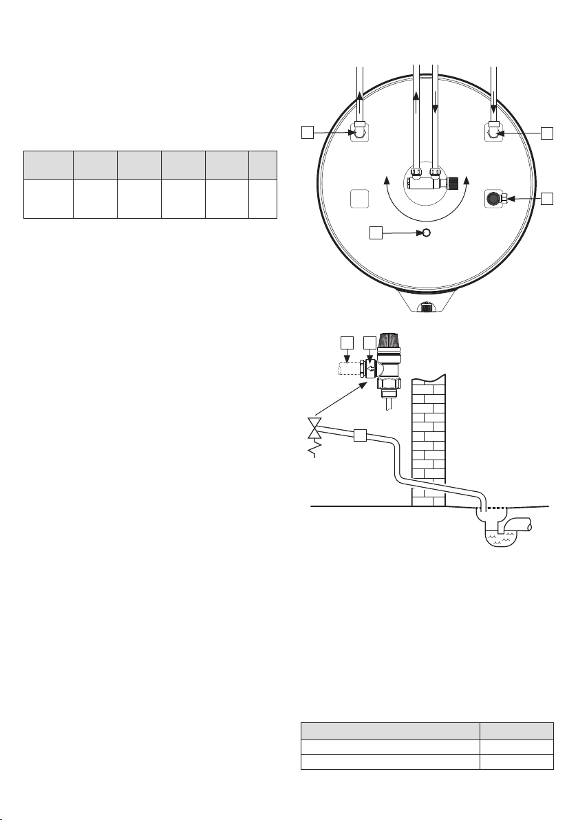
3.5.5 Torque settings
3.5 Pipe installation
3.5.1 Incoming water pressure
The efficiency of the product depends on the in-
coming cold water pressure. The water pressure
should be min. 2 bar and max. 6 bar throughout
the day. Excessive water pressure can be adjusted
by installing a pressure reduction valve.
3.5.2 Fitting cold and hot water pipes (CW-HW)
and overflow pipes
A) Turn the mixer valve to the desired position.
• Tighten ring clamp to the cylinder (see
3.5.3)
B) CW/HW pipes of suitable size run to mixer
valve and tightened (see 3.5.3)
• With larger pipes, a reducer with 1/2"
internal thread may be used.
C) Overflow pipe (1) in a suitable dimension
can be run to safety valve
• Connects to the 1/2” / ø15 mm outlet (2)
on the safety valve
• Must be fitted uninterruptable, undamaged
and frost-free with a fall to the drain.
3.5.3 Connection to coil
The product is equipped with pipe elbow con-
nectors to the coil (4). The elbows has a 3/4”
ring clamp connection for flow/return pipes.
Fit pipes of suitable material/quality and tight-
en the ring clamps.
3.5.4 Connection to solar heating/hot water/
HW circulation/sensor tube
SC comes with a sensor tube (ø10 mm internal)
factory-fitted (3). This is intended for a tem-
perature sensor to control any external heat
source connected to the coil. The sensor slot
can be removed if the connector is to be used
for a different function.
The product is designed to be permanently con-
nected to the mains water supply. Approved pipes
of the correct size should be used for installation.
The relevant standards and regulations must be
followed.
The product can be heated with water from
solar collectors. OSO can supply a kit to utilise
alternative energy sources, which prioritises
solar heat over the electric heating element.
The product is equipped with a factory fitted
P&T 10 bar/90-95°C pressure and temperature
valve (5).
360°
4
3
5
4
1
1 2

9
RECOMMENDATION
-Allow clearance to the floor. Screw the feet out a minimum of 15 mm from the bottom of the
product.
-Mains cable for wall socket (2) should be hidden under the channels in the bottom of the
product.
-If a non-return valve is fitted a reduction valve and expansion vessel should be fitted (to stop
dripping from the safety valve).
-If the maximum water pressure exceeds 6 bar in a 24-hour period, a reduction valve and expansion
vessel shall be fitted.
-
For installation in a rooms which does not conform to the wetroom standard, a watertight
drip tray with overflow pipe > 18 mm. inside diameter should be fitted under the product, in
addition to an automatic stop cock with sensor. This will prevent possible material damage.
3.5.6 Fitting instructions
3.5.7 Installation recommendation
!
CAUTION
!
The product shall be placed in a room with a gully/drain, in accordance with current local
regulations. Alternatively, fit an automatic stop valve with sensor and overflow from safety
valve to drain.
!
The product shall be properly aligned vertically and horizontally, on a floor or wall suitable for
the total weight of the product when in operation. See type plate.
!
The product must have a clearance for servicing of 40 cm in front of the cover / 10 cm over the
highest point.
!
WARNING
!
The product shall be filled with water before the power is switched on.
!
Any overflow pipe from the safety valve shall be in a suitable dimension and must be
uninterruptable, undamaged and frost-free with a fall to a suitable drain or gulley.
2
3.5.8 Pressure drop table coil
Product information:
Pressure drop (mbar) at volume flow: Cw value (m³/t):
Product
Coil sur-
face m²
540 L/h
(0,15L/s)
900 L/h
(0,25 L/s)
1800 L/h
(0,50 L/s)
2700 L/h
(0,75 L/s)
3600 L/h
(1,00L/s)
4500 L/h
(1,25 L/s)
5400 L/h
(1,50 L/s)
Volume flow @
1 bar pressure drop
SC 150 0.8 26 65 220 457 775 1160 1620 4.15
SC 200 1.0 35 82 283 586 1000 1520 2130 3.60
SC 300 1.1 37 91 284 590 1015 1530 2140 3.59
10
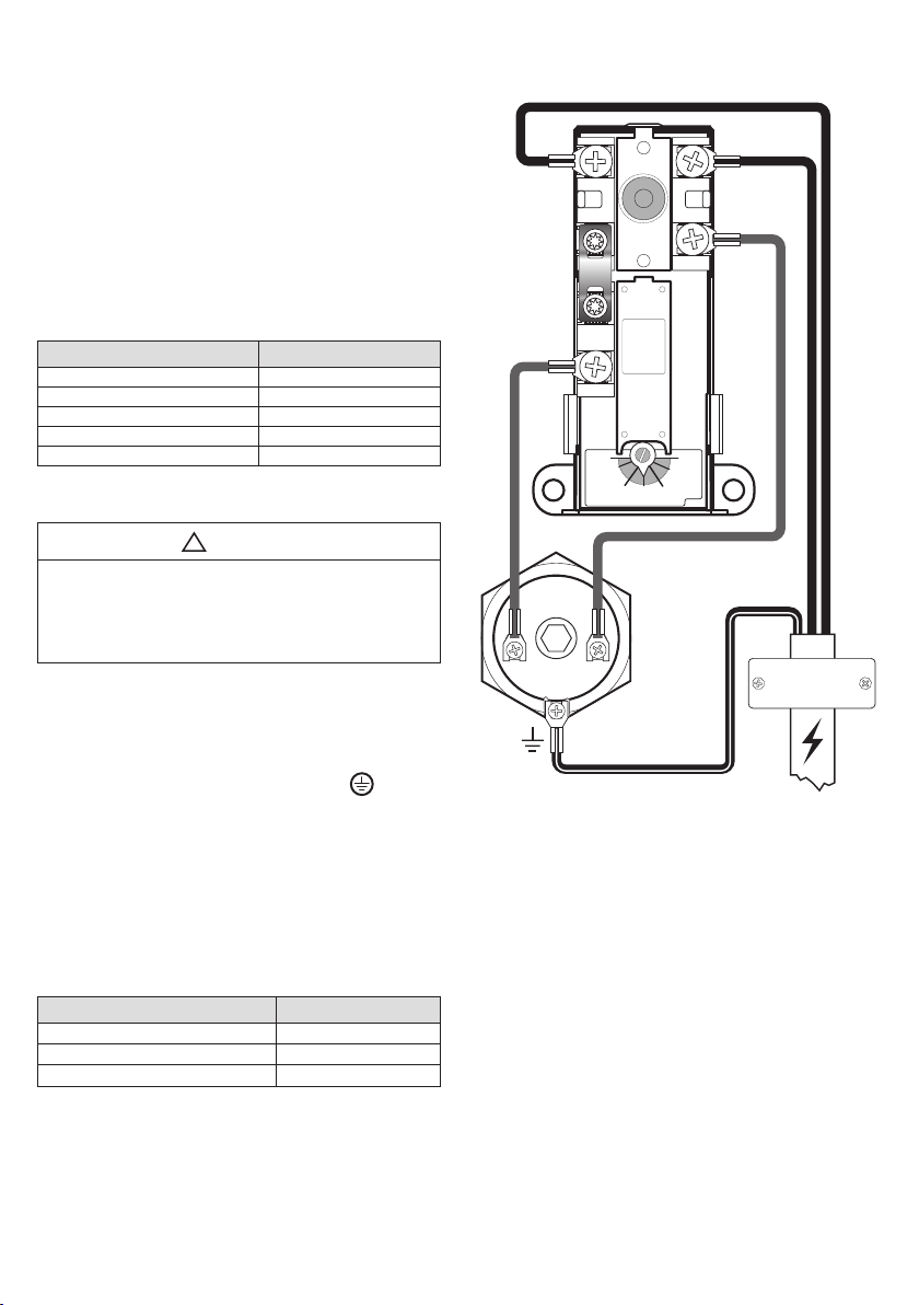
3.6.3 Torque settings
!
WARNING
Constant voltage present at terminals L and N.
Before any electrical work is done, the power
supply must be disconnected and secured
against activation while the work is in progress.
Component Torque
G1 1/4” heating element 60 Nm (+/- 5)
Thermostat screws 2 Nm (+/- 0.1)
Screw on the element head 2 Nm (+/- 0.1)
A) Live wire (L) connected to point ‘1’ on the
safety thermostat.
B) Neutral wire (N) connected to point ‘3’ on the
security thermostat.
C) Earth, yellow wire with green stripe
connected to terminal on the heating element
(hexagonal brass)
D) Internal wires from the element to the ther-
mostat are connected to point ‘4’ on the
safety thermostat and point ‘2’ on the work
thermostat. See illustration.
3.6 Electrical installation
3.6.1 Electrical components
Component Note
Safety thermostat 85°C thermal cut-out
Work thermostat 50-75°C adjustable
Heating element 2,8 kW 1-phase 230 V
Mains cable with plug Heat-resistant
Internal wires Heat-resistant
Fixed electric fittings should be used for installa-
tion in new homes or when changing an existing
electrical setup in accordance with regulations. A
mains cable with plug for wall socket can be used
when replacing the product without changing the
electrical setup. Any fixed electric fittings must be
installed by an authorised electrician. The relevant
standards and regulations must be followed.
3.6.2 Electrical connections in the junction box
Electrical connection, diagram
R
E
S
E
T
R
E
S
E
T
M2
1
2
3
4
THERM-O-DISC
60°C90°C
80°C 70°C
1
2
L N

11
RECOMMENDATION
-The mains cable supplied should be used with fixed electric fittings by removing the plug for the
wall socket. (Heat-resistant)
-Mains cable for wall socket/wall box should be hidden under one of the channels in the bottom of
the product.
-For products with ≤ 2kW capacity, a > 10A fuse / > 1.5# wire should be used*.
For products with ≤ 3kW capacity, a > 15A fuse / > 2.5# wire should be used (230V).
3.6.4 Fitting instructions
3.6.5 Fitting recommendation
!
WARNING
!
The product should be filled with water before the power is switched on.
!
Fixed electric fittings should be used for installation in new homes or when changing an existing
electrical setup in accordance with local regulations. A mains cable with plug for wall socket can
be used when replacing the product without changing the electrical setup.
!
The mains cable should withstand 90°C. A strain reliever must be fitted.
!
CAUTION
!
The product must have a clearance for servicing of 40 cm in front of the cover / 10 cm over the
highest point.
!
In case of damage to the mains cable and plug, it should be replaced with a specially adapted
mains cable from the manufacturer.
12
4.1 Filling with water
First check that all pipes are connected correctly.
Then proceed as follows:
A) Open a hot tap – leave it open
B) Turn the adjustable knob on the mixer valve all
the way to ‘+’.
C) Open the cold water supply to the product.
Check that the water from the open hot water tap is
flowing freely, without any air locks. Close hot tap.
Filling/emptying coil:
Follow the instructions for an
external heat source.
4.2 Turning on the power
When the cylinder has been filled with water, the
power can be switched on.
A) Insert plug into specified wall socket or turn on
on switch/fuse.
4.3 Setting the mixer valve
The outgoing hot water temperature from the
product to the taps in the home can be adjusted
with the knob on the mixer valve. Adjusting the
mixer valve does not affect the temperature of the
hot water in the product.
To adjust the temperature:
A) Turn the adjustable knob (1) all the way to ‘+’
B) Then turn the knob towards ‘-’ to the desired
temperature.
4.6 Handover to end-user
4. INITIAL COMMISSIONING
THE INSTALLER MUST:
Brief the end-user on safety and maintenance
instructions.
Brief the end-user on settings and emptying the
product.
Hand this installation manual over to the end-
user.
Enter contact details on the type plate on the
product.
4.4 Control points
A) Check that all pipe connections to/from the
product are tight and not leaking.
B) Check that the power supply to the product is
not at risk of exposure to mechanical, thermal
or chemical damage.
C) Check that any overflow pipe from the safety
valve is clear, undamaged and frost-free with
a fall to the drain.
D) Check that the product is standing firmly
vertically and horizontally.
!
WARNING
The water temperature in the product is 70°C and
could cause scalding. Before emptying, a hot tap
should be opened to the max. pressure/temper-
ature for min. 3 minutes.
After emptying, close the drain valve. Close all
open taps. Adjust the mixer valve to its original
setting. Refit the drain valve cover (2).
Turns Temperature
0 Approx. 70°C
1/4 Approx. 60°C
1/2 Approx. 50°C
3/4 Approx. 40°C
1
2
3
5
4
A) Disconnect the power supply.
B) Shut off incoming cold water supply.
C) Open a hot tap to the maximum
– leave open (prevents vacuum).
D) Open the mixer valve all the way to ‘+’.
E) Remove the cover over the drain valve (2) by
loosening the screw (5).
F) Open the drain valve (3). The product
empties.
4.5 Emptying of water

13
!
WARNING
Constant voltage present in the junction box. Be-
fore any electrical work is done, the power supply
must be disconnected and secured against acti-
vation while the work is in progress.
Turns Temperature
0 Approx. 70°C
1/4 Approx. 60°C
1/2 Approx. 50°C
3/4 Approx. 40°C
1
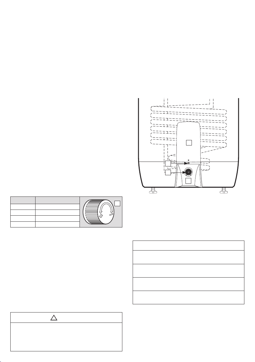
5.2 Maintenance
5.1 Settings
5.1.1 Thermostat setting
The thermostat on the product is adjustable from
50-75°C. The thermostat should not be set lower
than 65°C to prevent bacteria growth. To adjust
the temperature:
A) Disconnect the power supply.
B) Remove the cover (4) low down on the front of
the tank with a screwdriver.
C) Adjust the temperature on the thermostat (7)
with a screwdriver.
Fit the cover (4) before connecting the power
supply. Changing the temperature setting on the
thermostat only changes the temperature of the
water in the tank. Temperature to the taps is ad-
justed on the mixer valve.
5.1.2 Resetting the safety thermostat
The safety thermostat on the product cuts out
when there is a risk of overheating. This is reset
by removing the cover (4) and pressing the red
‘RESET’ button (6). If the thermostat cuts out re-
peatedly, contact the installer.
5.1.3 Adjusting the feet
The product is equipped with three factory-fit-
ted feet, adjustable from 0-40 mm. Screw the
feet out a minimum of 15 mm from the bottom
of the product. Adjust the feet individually un-
til the product is standing firmly vertically and
horizontally.
5.1.4 Setting the mixer valve
The outgoing hot water temperature from the
product to the taps in the home can be adjusted
with the knob on the mixer valve. To adjust the
temperature:
A) Turn the adjustable knob (1) all the way to ‘+’
B) Then turn the knob towards ‘-’ to the desired
temperature.
5. USER GUIDE
MAINTENANCE INSTRUCTIONS
!
Maintenance should be carried out by persons over 18 years of age, with suf-
ficient understanding.
!
Annual inspection of safety valve:
-Open valve for 1 min. by turning the knob (3) approx. 90 degrees to the open
position.
-Visually check that the water is flowing freely to the drain.
-YES = OK. Close the valve by turning the knob (3) a further 90 degrees to the
closed position.
-NO = NOT OK. Disconnect power supply / shut off water supply. Contact in-
staller.
60°C90°C
80°C 70°C
2
R
E
S
E
T
R
E
S
E
T
M2
1
2
3
4
1
7
6
3
14
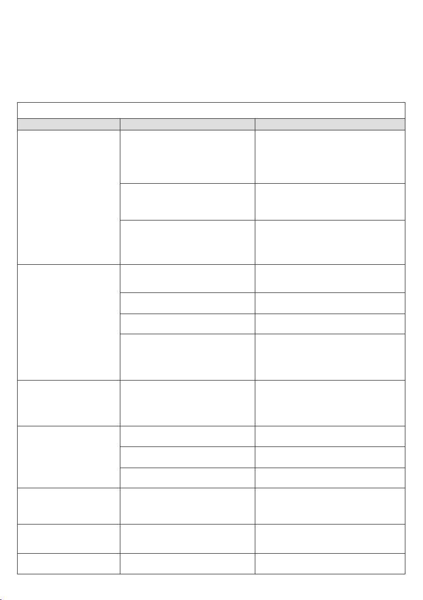
6.1 Faults and fixes
If problems arise when the product is in use,
check for possible faults and fixes in the table. If
the problem is not shown in the troubleshoot-
6. TROUBLESHOOTING
ing table or you are unsure what is wrong, con-
tact the installer (see type plate on the product)
or OSO Hotwater AS - see section 7.2.
TROUBLESHOOTING
Problem Possible cause of fault Possible solution
There is leakage/dripping
from the safety valve/
there is often water on the
floor by the cylinder in the
morning
Pressure reduction valve, water meter or
blocked non-return valve on the water
intake.
Water pressure into the home is too
high.
Fit AX expansion vessel with absorbs expan-
sion during heating, and fit pressure reduc-
tion valve for stable water pressure inside
the home. The pressure reduction valve is
adjusted in according to the pressure in the
expansion vessel. Contact auth. installer.
The safety valve is worn or there are par-
ticles stuck between the membrane and
the valve seat because the water is dirty
Try to flush with water through the safety
valve. Open valve for approx. 1 minute. See
section 5.2. If the valve still leaks, it must be
replaced. Contact auth. installer.
Leak from heating element.
Verify as follows: a) cut the electric supply, b)
unscrew the cover, c) visually check whether
there is a leak from the heating element. If so,
replace the gasket/heating element. Contact
auth. installer.
No hot water
Power supply interrupted. Verify that the fuse is on / the plug is
plugged in to the wall contact / the earth
breaker has not tripped.
Thermostat has cut out. Press the ‘RESET’ button on the safety ther-
mostat; see ‘User guide’.
Heating element is defective. Replace heating element. Contact auth. in-
staller.
Leak in hot water pipe
Verify as follows: a) close the mixer valve,
b) wait 2-3 hours, c) feel the mixer valve to
see whether it is hot. If so, there is a leak
in the hot water pipe or elsewhere. Contact
auth. installer.
Not enough hot water High consumption in the home.
Raise the temperature on the thermostat to
85°C; see ‘User guide’.
Switch to a larger OSO water heater. Con-
tact auth. installer.
Not high enough tem-
perature
The mixer valve is set for low tempera-
tures. Raise the temperature on the mixer valve;
see ‘User guide’.
The thermostat is set for low tempera-
tures. Raise the temperature on the thermostat to
85°C; see ‘User guide’.
Change from cold to hot water in taps. Contact auth. installer.
Fuse/earth breaker trips
repeatedly
Possible fault in the heater’s electrical
system.
Verify as follows: a) cut the electric supply, b)
unscrew the cover, c) visually check the junc-
tion box for any problems. If so, contact auth.
installer to check. Fit the cover.
Long time before the
water reaches the tap
Long stretch of pipe from water heater
to tap.
Fit circulation wire or heating cable to HW
pipe. Or fit an auxiliary heater by the tap.
Contact auth. installer.
Knocking in the pipes
when the hot tap is closed
Large pressure increase when the tap
is closed quickly. Completely normal. Fit AX expansion ves-
sel if troublesome. Contact auth. installer.

15
7.1 Customer service
In case of problems that cannot be resolved
with the aid of the troubleshooting guide in
this installation manual, contact either:
7. WARRANTY CONDITIONS
8. REMOVING THE PRODUCT
8.1 Removal
A) Disconnect the power supply.
B) Shut off incoming cold water supply.
C) Empty the product of water – see section 4.4.
D) Disconnect all pipes.
E) The product can now be removed.
1. Scope
OSO Hotwater AS (hereinafter called OSO) warrants for 2 years
from the date of purchase, that the Product will: i) conform to
OSO specication, ii) be free from defects in materials and
workmanship, subject to conditions below. All components carry
a 2-year warranty.
The warranty is voluntarily extended by OSO to 5 years for the
stainless steel inner tank. This extended warranty only applies
to Products purchased by a consumer, that has been installed
for private use and that has been distributed by OSO or by a
distributor where the Products have been originally sold by OSO.
The extended warranty does not apply to Products purchased by
commercial entities or for Products that have been installed for
commercial use. These shall be subject only to the mandatory
provisions of the law. The conditions and limitations set out below
shall apply.
2. Coverage
If a defect arises and a valid claim is received within the statutory
warranty period, at its option and to the extent permitted by law,
OSO shall either; i) repair the defect, or; ii) replace the product
with a product that is identical or similar in function, or; iii) refund
the purchase price.
If a defect arises and a valid claim is received after the statutory
warranty period has expired, but within the extended warranty
period, OSO will supply a product that is identical or similar in
function. OSO will in such cases not cover any other associated
costs.
Any exchanged Product or component will become the legal
property of OSO. Any valid claim or service does not extend the
original warranty. The replacement Product or part does not carry
a new warranty.
3. Conditions
The Product is manufactured to suit most public water supplies.
However, there are certain water chemistries (outlined below)
that can have a detrimental eect on the Product and its life
expectancy. If there are uncertainties regarding water quality, the
local water supply authority can supply the necessary data.
The warranty applies only if the conditions set out below are met
in full:
• The Product has been installed by a professional installer,
in accordance with the instructions in the installation
manual and all relevant Codes of Practice and Regulations
in force at the time of installation.
• The Product has not been modied in any way, tampered
with or subjected to misuse and no factory tted parts have
been removed for unauthorized repair or replacement.
• The Product has only been connected to a domestic mains
water supply in compliance with the European Drinking
Water Directive EN 98/83 EC, or latest version. The water
should not be aggressive, i.e. the water chemistry shall
comply with the following:
- Chloride < 250 mg / L
- Electric Conductivity (EC) @25°C < 750 uS / cm
- Saturation Index (LSI) @80°C > - 1,0 / < 0,8
- pH level > 6,0 / < 9,5
• The immersion heater has not been exposed to hardness
levels exceeding 10°dH (180 ppm CaCO3). A water
softener is recommended in such cases.
• Any disinfection has been carried out without aecting
the Product in any way whatsoever. The Product shall be
isolated from any system chlorination.
• The Product has been in regular use from the date of
installation. If the Product is not intended to be used for 60
days or more, it must be drained.
• Service and/or repair shall be done according to the
installation manual and all relevant codes of practice. Any
replacement parts used shall be original OSO spare parts.
• Any third-party costs associated with any claim has been
authorized in advance by OSO in writing.
• The purchase invoice and/or installation invoice, a water
sample as well as the defective product is made available
to OSO upon request.
Failure to follow these instructions and conditions may result in
product failure, and water escaping from the Product.
4. Limitations
The warranty does not cover:
• Any fault or costs arising from incorrect installation,
incorrect application, lack of regular maintenance
in accordance with the installation manual, neglect,
accidental or malicious damage, misuse, any alteration,
tampering or repair carried out by a non-professional, any
fault arising from the tampering with or removal of any
factory tted safety components or measures.
• Any consequential damage or any indirect loss caused by
any failure or malfunction of the Product whatsoever.
• Any pipework or any equipment connected to the Product.
• The eects of frost, lightning, voltage variation, lack
of water, dry boiling, excess pressure or chlorination
procedures.
• The eects of stagnant (de-aerated) water if the Product
has been left unused for more than 60 days consecutively.
• Damage caused during transportation. Buyer shall give the
carrier notice of such damage.
• Costs arising if the Product is not immediately accessible
for servicing.
These warranties do not aect the Buyer’s statutory rights.
8.2 Returns scheme
This product is recyclable and should be taken
to the environmental recycling centre. If the
product is to be replaced with a new one, the
installer can take the old cylinder away for re-
cycling.
A) The installer who supplied the product.
B) OSO Hotwater AS: Tel.: +47 32 25 00 00

OSO Hotwater AS
Industriveien 1
3300 Hokksund - Norway
Tel: + 47 32 25 00 00
www.osohotwater.com
© This installation manual and all its content is protected by copyright and
may be reproduced or distributed only with written consent from the manufacturer.
We reserve the right to make changes without notice.
This manual suits for next models
5
Table of contents
Other OSO Water Heater manuals


Popular Water Heater manuals by other brands


State Water Heaters
State Water Heaters 184671-000 instruction manual

Airxcel
Airxcel SW5EA Operating, installation and service manual

3P Technik
3P Technik 3P Barrique instruction sheet

GE
GE 50T06AAG Energy guide

Bradford White
Bradford White ECO-DEFENDER U130T*FRN Service manual

HTP
HTP SSU-10DB Installation, operation, maintenance, & troubleshooting

Bradford White
Bradford White Magnum D75T125E3N Installation & operation manual

Drazice
Drazice OKHE ONE20 OPERATING AND INSTALLATION Manual

onsen
onsen 14L manual

Modena
Modena EI 3D Series manual

Argo
Argo Technibel TANK 200L Usage and maintenance manual

ThermoBar
ThermoBar 130 Installation, user instructions and care