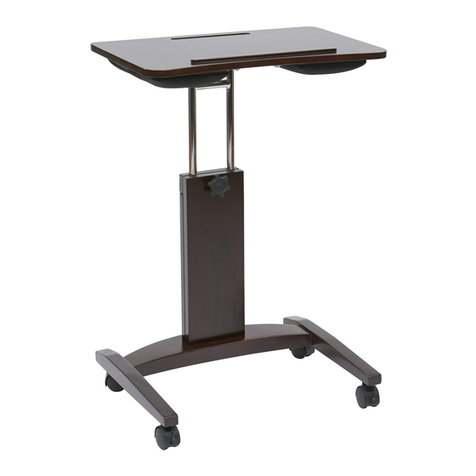
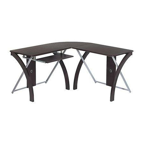
OSP Designs XT25L User manual
Other OSP Designs Indoor Furnishing manuals
OSP Designs
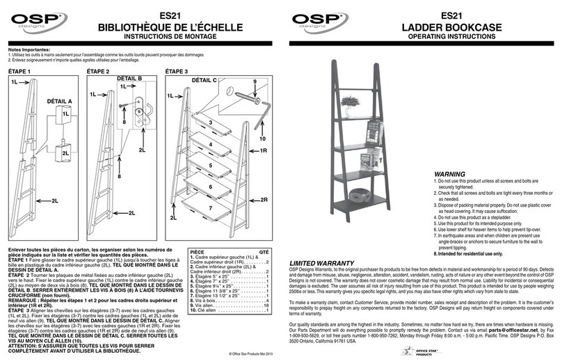
OSP Designs ES21 User manual

OSP Designs
OSP Designs Sierra SRA25 User manual
OSP Designs
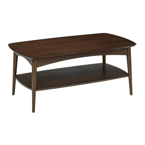
OSP Designs COPENHAGEN CPH12 User manual
OSP Designs
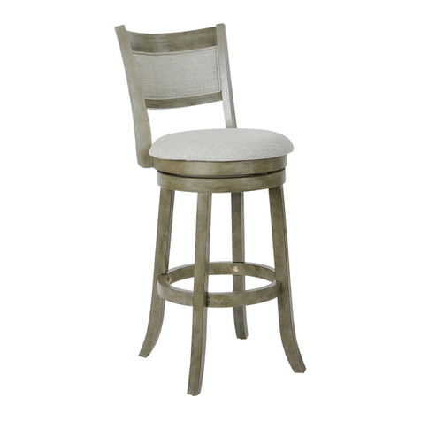
OSP Designs MET12430 User manual

OSP Designs
OSP Designs COSMO CSM2624-ES User manual

OSP Designs
OSP Designs SANTA CRUZ STCZ08 User manual

OSP Designs
OSP Designs ES21 User manual

OSP Designs
OSP Designs ASHLAND ASHCSL User manual
OSP Designs
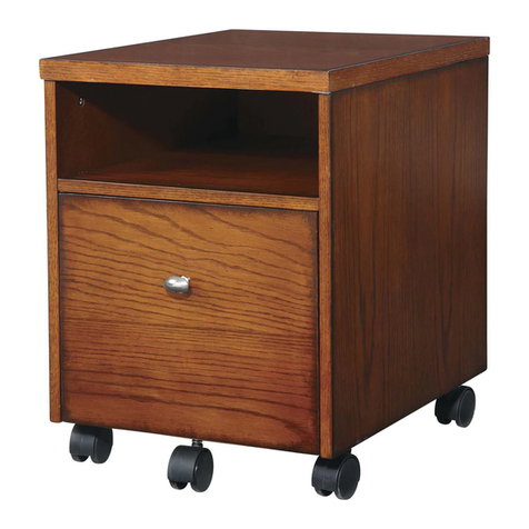
OSP Designs AURORA AR30 User manual

OSP Designs
OSP Designs QTN297 User manual

OSP Designs
OSP Designs SANTA CRUZ STCZ09 User manual
OSP Designs
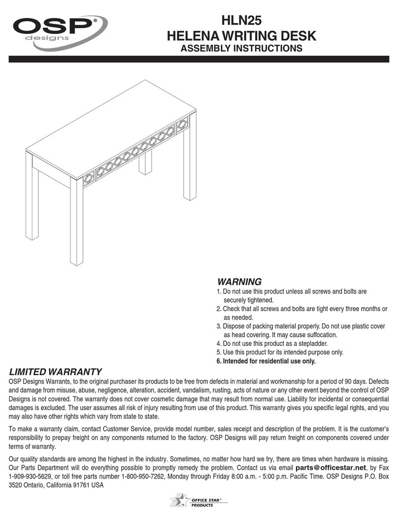
OSP Designs HELENA HLN25 User manual
OSP Designs
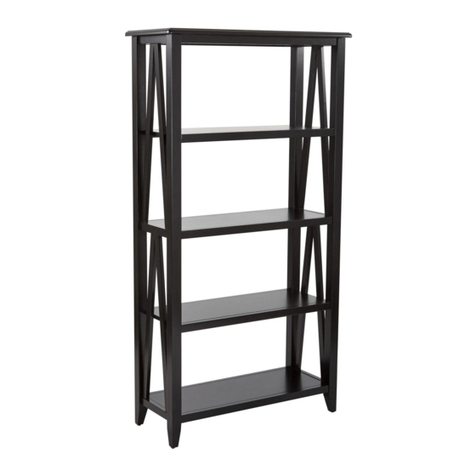
OSP Designs STCZ275 User manual

OSP Designs
OSP Designs EM39800 User manual

OSP Designs
OSP Designs HELENA HLN19 User manual
OSP Designs
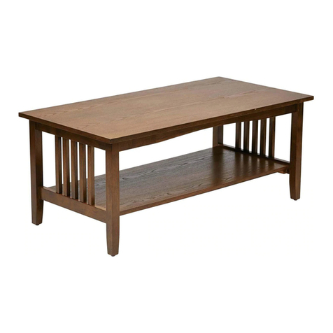
OSP Designs SIERRA COFFEE TABLE SRA12 User manual
OSP Designs
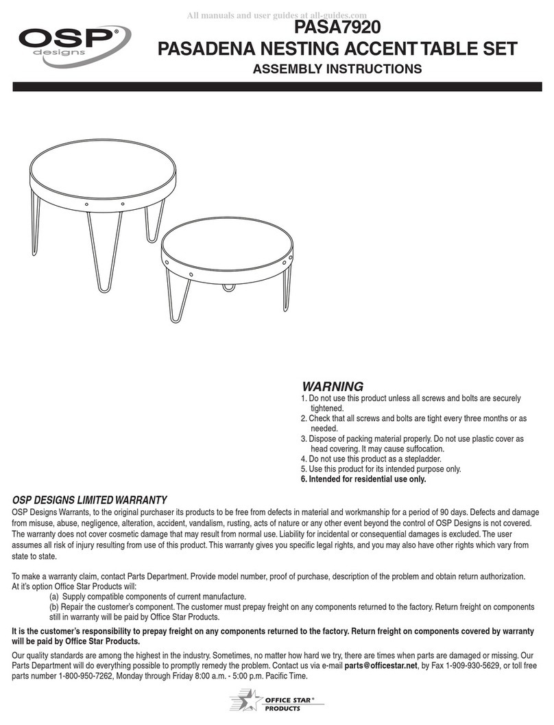
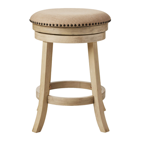
OSP Designs PASADENA NESTING PASA7920 User manual
OSP Designs
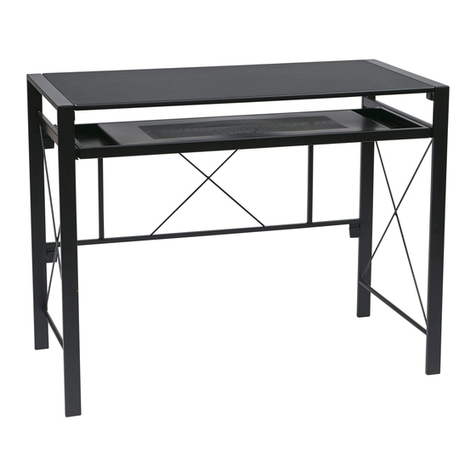
OSP Designs MET17824 User manual
OSP Designs
OSP Designs CRS25 User manual

OSP Designs
OSP Designs KNT686 User manual
Popular Indoor Furnishing manuals by other brands

FMD Furniture
FMD Furniture MADAGASKAR 3 806-003 Assembly instructions
Jofran
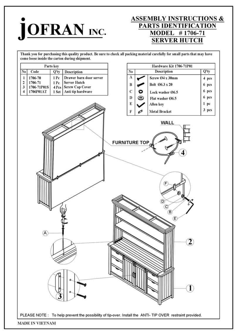
Jofran 1706-71 quick start guide
Julian Bowen
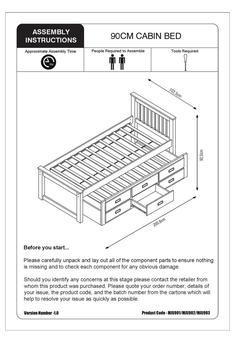
Julian Bowen MAI901 Assembly instructions

The Land of Nod
The Land of Nod Hampshire Daybed Assembly instructions
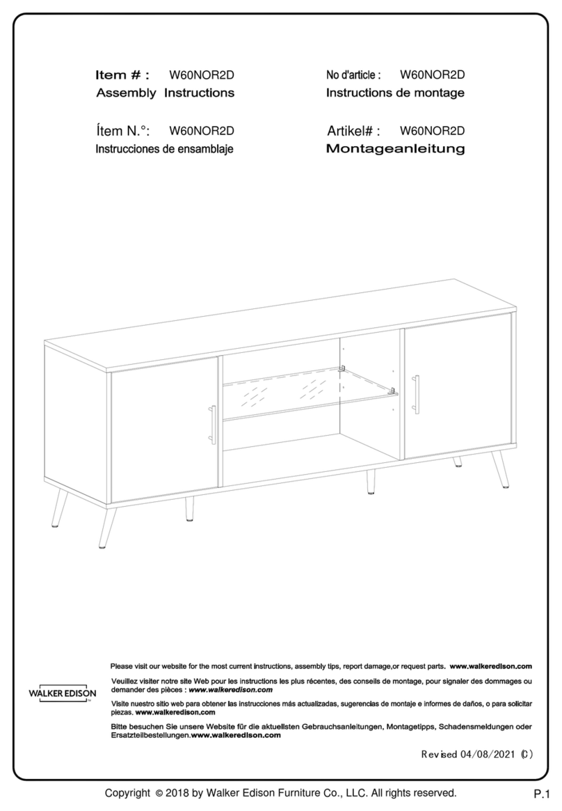
Walker Edison
Walker Edison W60NOR2D Assembly instructions

Walker Edison
Walker Edison KOCL8K Assembly instructions
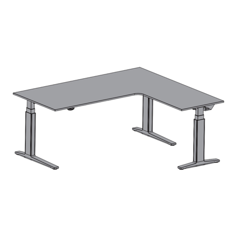
TRADINGZONE
TRADINGZONE SMARTLINE SITTING/STANDING CORNER TABLE... Assembly and operating instructions
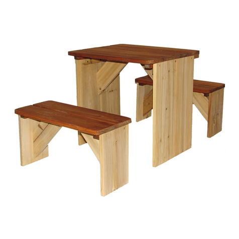
AXI.COM
AXI.COM Zidzed user manual
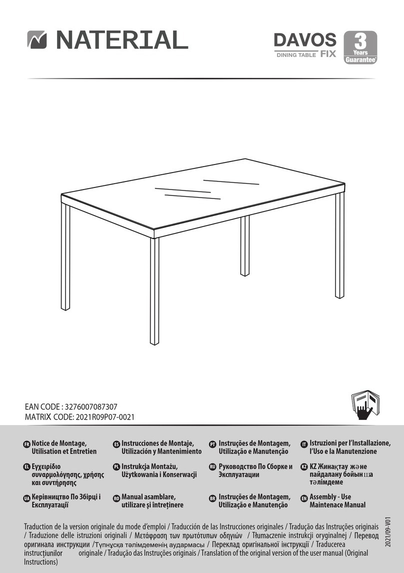
Naterial
Naterial DAVOS 2021R09P07-0021 Assembly- Use Maintenace Manual

Grandinroad
Grandinroad 181520 Assembly instructions

Steve Silver
Steve Silver AH850C quick start guide

Forte
Forte Tempra T2KR70 Assembling Instruction


