ET1111 Series Installation & Operation Manual
www.ot-systems.com 6
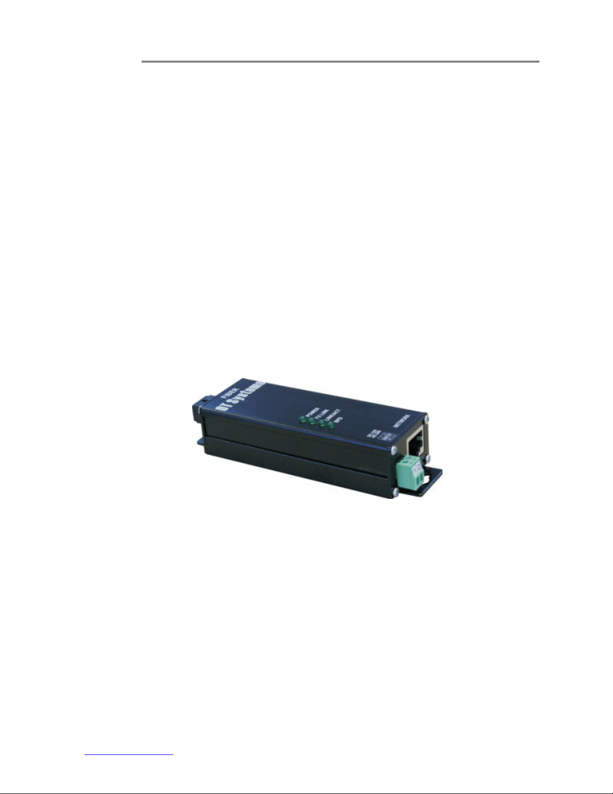
3.3 Selecting a site for the Media Converter
As with any electric device, you should place the Media Converter where it will not be
subjected to extreme temperatures, humidity, or electromagnetic interference. Specifically,
the site you select should meet the following requirements:
- The ambient temperature should be between -10 to +60 degrees Celsius.
- The relative humidity should be less than 95 percent, non-condensing.
- Surrounding electrical devices should not exceed the electromagnetic field (RFC)
standards.
- Make sure that the Media Converter receives adequate ventilation.
- The power outlet should be within 1.8 meters of the Media Converter.
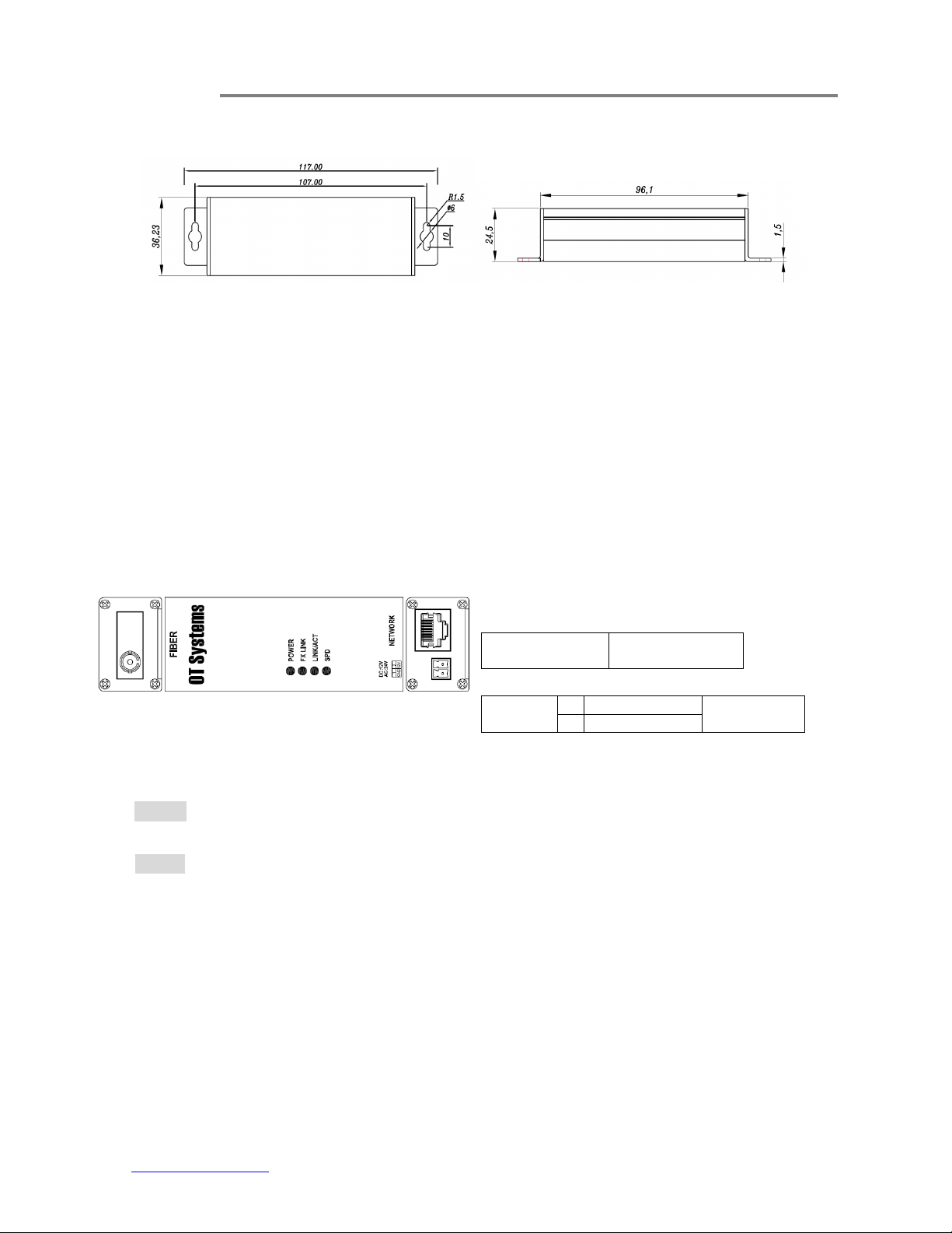
3.4 Installation
This chapter gives step-by-step instructions about how to install the Media Converter:
a) Mount the ET1111 onto a fixture or camera housings, e.g. a plank, (either on the
wall or on a flat surface) with two screws through the holes on the mounting
frame to secure it in position.
b) The power supply should also be mounted on the same fixture or in the proximity
for connection of the supply cables to the unit, provided that an AC power supply
socket is nearby for powering the adaptor.
c) Connect all the signal inputs and outputs at the unit with appropriate cables: fiber
optic cable for optical link and UTP/STP Cat 5 cable for Ethernet. Please refer to
Section 4.1 for the details.
d) Once the unit is powered up, check that the POWER LED on the unit is lit. If not,
check the power supply cable connections between the unit and the power
supply socket.
e) With all the signals available at the physical ports, check the status of LEDs
located on the unit. With correct status of each LED, installation is now completed
[for LEDs status, see Operational Guides on this manual’s Section (5)].