www.ot-systems.com 6
(3) Installation
3.1 General
All OT Systems products are thoroughly inspected, tested and securely packed before
delivery to ensure a stable, intact and trouble-free service. Please check the equipment upon
receipt for any visible damage which may have been caused during transit.
The FT100 Series standalone units (Fig. 3.1) can be either horizontally or vertically
wall-mounted, or mounted on any fixtures, etc. The Standalone unit works with an external power
adaptor FT-PA/12V powered by a local residential power supply outlet.
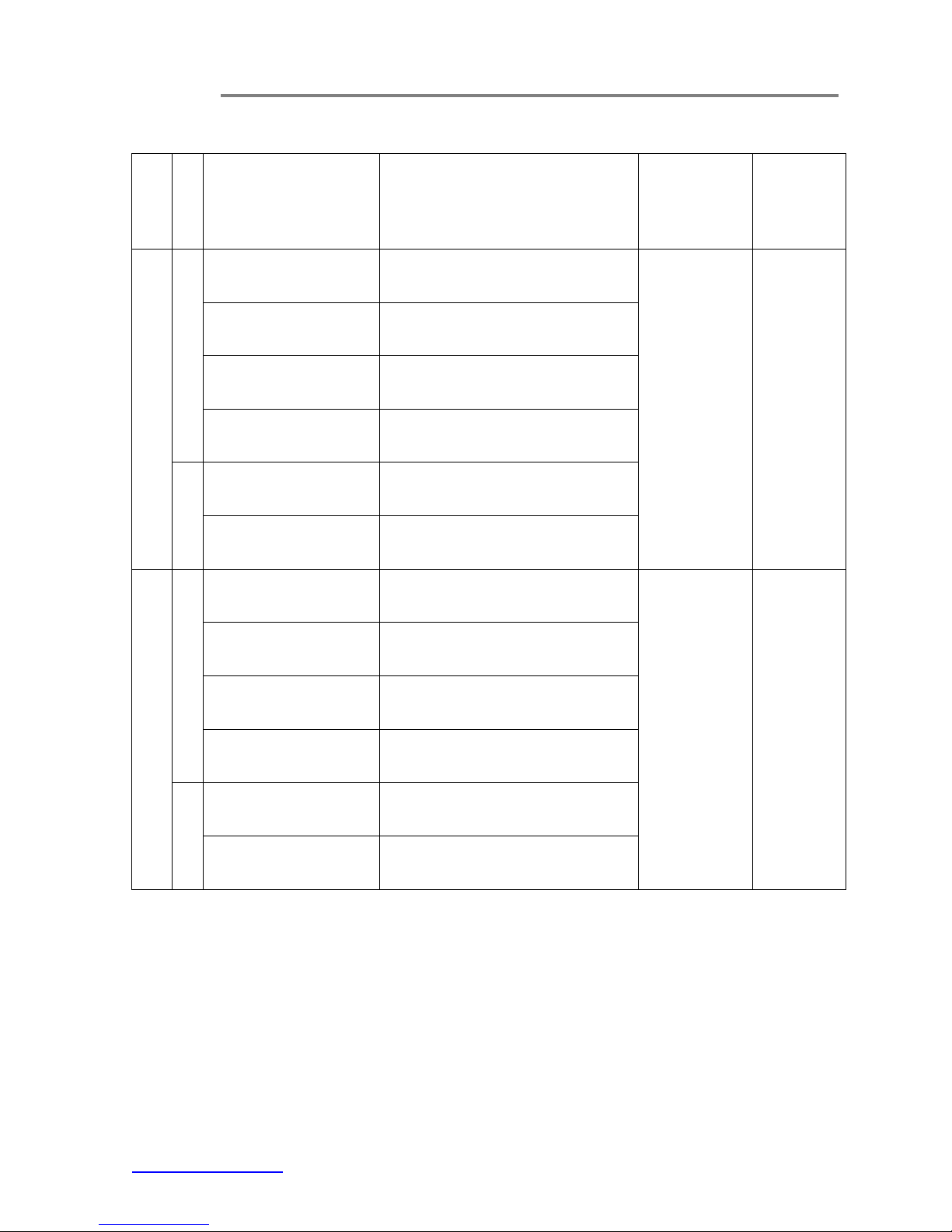
The FT100 Series card modules are housed inside the FT-C18 rack-mount chassis (Fig. 3.2)
with an included power supply unit. The whole chassis is powered by a local residential power
supply outlet. FT-C18 is a standard 19” (483mm) rack-mount chassis which occupies 4 rack units
space (177.8mm) in height. Each FT100 card module occupies one slot space inside and a total
of 18 cards can be housed inside the chassis.
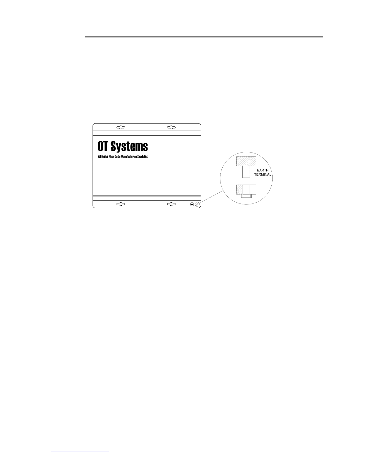
3.2 Standalone unit installation
a) Mount the standalone unit onto a fixture, e.g. a plank, (either on the wall or on a flat surface)
with four screws piercing through the holes on the mounting frame to secure it in position.
b) The provided power adaptor should also be mounted on the same fixture or in the proximity
for connection of the supply cables to the unit, provided that an AC power supply socket is
nearby for powering the adaptor.
c) Once the unit is powered up, check that the red POWER LED on the unit is lit. If not, check
the power supply cable connections between the unit and the power supply socket.
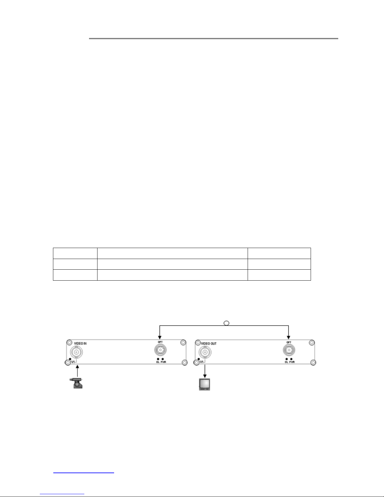
d) Connect all the signal inputs and outputs at the back of the unit with appropriate cables:
fiber optic cable for optical link and BNC cable for video input/output (Tx/Rx).
e) With all the signals available at the input and output ports, check the status of LEDs located
on the unit. With correct status of each LED, installation is now completed [for LEDs status, see
Operational Guides on this manual’s section (5)].
Fig. 3.1 Standalone unit Fig. 3.2 FT-C18 chassis