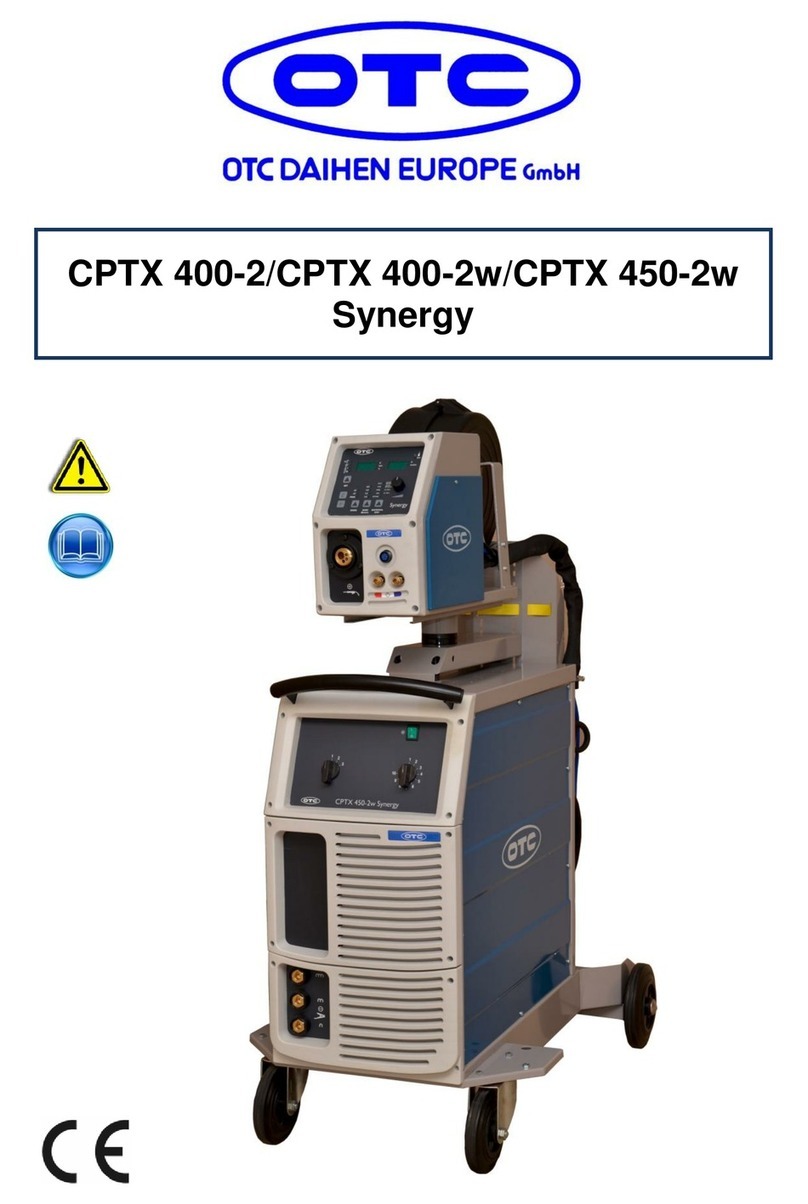
OTC DTX-2200 AC/DC User manual

DTX-2200 AC/DC
DTX-3000 AC/DC
User Manual

Contents
2
DTX-2200-3000 AC/DC
1 Contents
1Contents ........................................................................................................................................................... 2
2Foreword .......................................................................................................................................................... 4
3Regulations for the prevention of accidents...................................................................................................... 6
3.1Connection of the power source............................................................................................................. 6
3.2Operator protection ................................................................................................................................ 7
3.3Prevention of fire and slag ..................................................................................................................... 7
3.4Risk of poisoning.................................................................................................................................... 8
3.5Installation of the power source.............................................................................................................. 8
3.6Transport of the power source ............................................................................................................... 9
3.7Safety measures .................................................................................................................................... 9
4Description ..................................................................................................................................................... 11
5Features ......................................................................................................................................................... 11
6Technical Data ............................................................................................................................................... 13
7Usage Limits (IEC 60974-1) ........................................................................................................................... 14
8Open the packing ........................................................................................................................................... 14
9
Serial number
................................................................................................................................................ 14
10
How to lift up the machine
...................................................................................................................... 15
11
Installation
............................................................................................................................................... 15
12
Prepare the machine for welding
.......................................................................................................... 16
12.1Connection to the electrical supply....................................................................................................... 16
13Outer view of the DTX-202 TIG ................................................................................................................ 17
14Operation.................................................................................................................................................. 18
14.1TIG-welding.......................................................................................................................................... 18
14.1.1Part to be welded............................................................................................................................. 20
14.1.2Welding Parameters ........................................................................................................................ 20
14.2Electrode welding (MMA) ..................................................................................................................... 21
14.2.1Part to be welded............................................................................................................................. 21
14.2.2Welding Parameters ........................................................................................................................ 22
14.3Control panel MTA22 / MTA30............................................................................................................. 23
14.3.1Panel surface................................................................................................................................... 23
14.3.2
Displaying the Software version installed
.................................................................................. 29
14.3.3
Electrode welding (MMA)
.............................................................................................................. 30
14.3.4
TIG “AC” welding
............................................................................................................................ 31
14.3.5
TIG „DC“ -welding
........................................................................................................................... 37
14.3.6
TIG “AC and LIFT DC” welding with the SPOT WELDING function ON...................................... 38
14.3.7
TIG HF DC welding with TACK function active and single ColdTack point ................................. 39
14.3.8
TIG HF DC welding with TACK function active and multi ColdTack point ................................... 40
14.3.9
TIG-welding – Welding parameters............................................................................................... 42
14.3.10
Editing the maximum and
minimum
limits for welding parameters........................................... 54
14.3.11
Creating and memorising automatic welding points
............................................................ 55
14.3.12PROGRAMMED and/or MANUAL welding.................................................................................. 56
14.3.13
Calling up saved programs
....................................................................................................... 57
14.3.14
Viewing the p
arameters set
...................................................................................................... 58
14.3.15
Activating the VRD-device
......................................................................................................... 58
14.3.16
Auxiliary functions
.................................................................................................................... 59
14.3.17Factory default............................................................................................................................. 59
14.3.18
Error and protection conditions
................................................................................................. 60
15Optional .................................................................................................................................................... 62
15.1MANUAL REMOTE CONTROL ........................................................................................................... 62
15.2
FOOT SWITCH
.................................................................................................................................... 62

Contents
3
DTX-2200-3000 AC/DC
15.3AIR AND/OR WATER-COOLED TORCH UP/DOWN .......................................................................... 62
15.4Interfacing accessories (optional)......................................................................................................... 63
16Maintenance............................................................................................................................................. 64
16.1Daily ..................................................................................................................................................... 64
16.2Weekly ................................................................................................................................................. 64
16.3All six months ....................................................................................................................................... 64
17TROUBLESHOOTING ............................................................................................................................. 65
17.1
DIGITAL INTERFACE PCB REPLACEMENT
................................................................................ 65
17.2
Adjustment
of
electronic circuit
board
............................................................................................. 65
17.3
MEANING OF GRAPHIC SYMBOLS ON THE MACHINE
............................................................. 66
18WIRING DIAGRAM .................................................................................................................................. 67
18.1Key to the electrical diagram................................................................................................................ 67
18.2Colour key............................................................................................................................................ 68
19Spare parts list ......................................................................................................................................... 73
19.1Ordering spare parts ............................................................................................................................ 79

Foreword
4
DTX-2200-3000 AC/DC
2 Foreword
Thank you for choosing our product. Your new welding equipment from OTC DAIHEN EUROPE GmbH offers you
the highest quality and latest technology.
To exploit the full capabilities of this device and to enjoy it for many years, please read these instructions carefully
before connecting and commissioning the device. It’s very important to operate your device as instructed.
The reliability and functionality of the device can only be guaranteed if you follow the general safety and accident
prevention Instructions in this manual. We assume no liability for damages caused by improper use or incorrect
operation.
Important
Please ensure that all persons who operate with the device have red and understood the operating instructions in
this manual. If you don’t have sufficient knowledge and experience concerning the operation and the safe use of
this machine, please contact our staff.
If you have any questions about the installation, the connection or the use of this device you can always contact
the manufacturer (customer service department).
Please keep this manual at a safe place in case of need to be
able to access it at any time!
Warning
The arc welding equipments from the company OTC DAIHEN EUROPE GmbH correspond to the "EN 50199
standard" for electromagnetic compatibility. The operators are required to operate according to manufacturer's
instructions when installing and handling the device.
In case of electromagnetic interference, the operators have to contact the manufacturer and search a solution.

Foreword
5
DTX-2200-3000 AC/DC
Electric and Magnetic Fields
During the operations of the welding machine an electromagnetic field (EMF) can be created and may
caused health problems.
The operator is responsible for the proper installation and use of the device according to the manufacturer’s
instructions. In case of electromagnetic interference, it’s in the responsibility of the user to remove these
(technical support can be requested).
Before the installation and commissioning of the equipment, the user has to consider potential
electromagnetic interference in its environment.
The following should be considered:
Other supply, control, signal and telephone cables over, under and in the adjacent area of the
welding machine.
Radio, television sets and receivers.
Computer and other control devices.
Security and surveillance equipment.
The health status of all attendant persons, especially people with heart pacemakers, hearing aids,
etc.
Instruments and equipment used for the calibration.
The protection of the other devices in the vicinity of the welding unit. These must be compatible.
Additional precautions may be necessary.
The time of day in which the welding or other work will be performed.
Recommendation to reduce the electromagnetic interference
Installation of a filter on the supply.
Use of cables with protective wrapping.
Proper maintenance of the system.
The housing must be closed during the operation.
The weld cables as short as possible.
Grounding of the work piece.

Regulations for the prevention of accidents
6
DTX-2200-3000 AC/DC
3 Regulations for the prevention of accidents
The use of welding equipment and welding itself are always associated with a certain safety risk. Therefore each
set up and operation of the device assumes that the instruction manual is understood and complied. The properly
used welding machine grants a high degree of operational security but can, in case of improper handling, lead to
property and personal damage.
Be sure that you observe the following safety rules:
3.1 Connection of the power source
The installation and maintenance of the system must be carried out in accordance with the general
safety and accident prevention regulations of the legislature.
The state of the power cord and plug must be checked and any damage eliminated. The
electrical equipment must be tested at regular intervals. Use cables of sufficient diameter.
The ground cable must be fastened as close as possible to the work area of the work piece be. Is it
connected directly to the building design or too far away from the work area, this can lead to energy
loss or discharging.
The system may not be used in damp areas and in no case encounter water or other liquids.
Direct contact with hands or with wet clothing to components that might be under tension is to be
avoided. Make sure that your gloves and protective clothing are dry.
When working in damp rooms or on metal surfaces, use protective gloves and work shoes with
rubber soles.
The system has to be cut off at each interruption, even at sudden loss of power. Accidental ground
contact can lead to overheating of the system and cause a fire. The system must therefore never
be turned on without supervision.

Regulations for the prevention of accidents
7
DTX-2200-3000 AC/DC
3.2 Operator protection
All people must be protected during the welding process, with appropriate measures against UV
radiation, noise, heat and gas pollutants emitted during welding. Never expose yourself to the influences
of arc and the hot metal slag without a protective mask and appropriate protection. Welding work without
consideration of these standards could cause serious health problems.
Always wear protective clothing: gloves (fire resistant), shirts with long sleeves, long pants
without cuffs and high closed shoes. Protective clothing protects the skin from the arc and
the hot metal.
Wearing a cap or a helmet is required!
Protect your eyes with safety glasses and adequate protection level (at least NR10 or
more). The same goes for the ears, face and skin. All people must be informed of the
dangers.
In the workroom, all people have to wear earmuffs!
When you manually remove the hot metal slag wearing safety glasses with side flaps is required.
Present persons have to keep their distance!
The entire welding area must be secured with a fireproof bulkhead, in order to protect present
persons from the created radiation, slag and sparks.
3.3 Prevention of fire and slag
The glowing slag and the resulting spark can ignite a fire at any time. Explosions or the outbreak of fire
can be prevented if you meet the following requirements:
Remove all flammable objects in the vicinity of the welding machine or cover them with refractory
materials.
These flammable objects include the following: wood, saw dust, clothing, paints and solvents, gasoline,
fuel oil, natural gas, acetylene, propane, etc.
Even after emptying the collection vessels and pipes is caution while welding very important.
A fire extinguisher, sand or water must always be present in the workplace in order to be able to react quickly in
case of fire.
Never weld at adjoining tanks or piping. Do not weld in open containers or pipes that may contain flammable
substances.

Regulations for the prevention of accidents
8
DTX-2200-3000 AC/DC
3.4 Risk of poisoning
Gases and fumes that are harmful when inhaled for a longer time can be released while
welding.
Because of this, the following safety guidelines have to be observed:
Ensure that you have adequate ventilation for the work area.
During the processing of materials such as, beryllium, potassium, zinc, or galvanized and painted
pieces, you must set up forced ventilation.
The operator has to protect his airway with appropriate equipment.
Wherever a sufficient air supply is ensured, you must use respirators and additional air supply.
In small rooms (in boilers, in the ditch, etc.), the welders have to be backed up by another person.
Provided that all requirements are met to prevent accidents.
Weld never near degreasing and painting, because there may be released bleach-water, which
transform under the influence of heat into phosgene, a highly toxic gas.
The signs of inadequate ventilation or a possible poisoning are charms in the eyes, nose and
throat. In this case, you have to interrupt the welding work and ventilate the work area. If you feel
uncomfortable anyway stop the welding work.
3.5 Installation of the power source
When setting up the welding machine the following requirements have to be obeyed:
All switch ports and devices must be accessible.
Thus, the source can be adequately ventilated, never set up the device in a narrow space. Avoid
dirty and dusty areas, so the device can absorb no foreign body.
The unit including all cables should not impede the ability to work and the passage to other rooms.
The unit must be secured against falling down.
Setting up objects higher, increases the risk that it may fall off during the work.

Regulations for the prevention of accidents
9
DTX-2200-3000 AC/DC
3.6 Transport of the power source
The unit is generally suitable for transport.
The following requirements must be made to ensure an ease transport:
The device may only be lifted and transported with the provided handle.
Before lifting or transportation all connectors and cables have to be removed.
Never pull this device on the cables or plug.
3.7 Safety measures
Before using the machine, the following rules have to be observed:
Ensure the appropriate working conditions for the welder. At the work area no inflammable
substances may be presented. Reconciliation of dust and other substances that prevent the
isolation of the device must be removed.
Back up the welder properly when working outdoors.
If you notice any overheating or smoke, fire, find strange sounds and unusual vibrations, you have
to switch off the machine immediately and disconnect it from power. In such cases the device has
to be inspected by an expert.
In the event of a power outage, or when you realize power on the housing of the device, switch off
the machine immediately and disconnect it from power. The same applies in the case of
mechanical damage.
Too high humidity in the work area can reduce the insulation class and cause a short circuit.
During welding some parts of the machine exceeds 100 °C. Therefore these parts are protected
with a thermostat. Whenever you will notice any overheating, you have to turn off the power
immediately.
Use environment:
The device is not suitable for bathrooms, showers, swimming pools or similar areas. If it’s
necessary to work in these environments, you have to ensure that water can’t damage the
machine. The welding equipment isn’t suitable for use in rain or snow!
The welding equipment can’t be used in areas, where it is exposed to shock or vibration. Areas that
should be avoided necessarily are for example, road-, rail- and cable handling equipment, aircraft,
water crafts, cranes and parts of machine tools.

Regulations for the prevention of accidents
10
DTX-2200-3000 AC/DC
Dust and cooling system:
The device has to be positioned in a way that sufficient air can flow through the cooling fins and the
cooling channels. The unit adjusts the cooling system automatically! Please pay attention, that no
metal dust can be sucked.
Stability:
The unit can be installed on up to 15° tilted planes. If the plane is tilted steeply, the welding
equipment can overturn!

Description
11
DTX-2200-3000 AC/DC
4 Description
DTX-2200 AC/DC
Powerful, compact, and light weight, the DTX-2200 AC/DC units represent the most innovative, high
performance, and technically advanced single-phase inverter generators for TIG welding to be found. The PFC
(Power Factor Correction) device fitted optimises absorption of energy from the mains, means that these high
power generators can be connected to power supply systems with 16A fuses without any problem. The user
friendly digital control and advanced functions ensure complete stability of all welding parameters, guaranteeing
high quality TIG welding for all metals, aluminium, and its alloys, as well as MMA welding with any type of
electrode. The DTX-2200 AC/DC units are the ideal solution for all professional welding applications and for
maintenance work that calls for power and portability.
DTX-3000 AC/DC
Using the most modern IGBT based inverter technology, the three-phase TIG generator with high frequency
DTX-3000 AC/DC ignition, comes with an innovative digital control for all welding parameters.
Technologically cutting-edge, robust, easy to use with both direct and alternating current, fitted with high potential
digital control, this generator can be used for high quality TIG welding of all metals including aluminium and
alloys. This means that the machine is particularly suitable for specific uses in industry and the maintenance
sector.
It also guarantees excellent performance for MMA welding, even when using particularly difficult cellulosic and
basic electrodes.
5 Features
The characteristics found in all welding machines in the DTX AC/ DC range are:
• Innovative and compact design.
• Compact size and light weight for easy transportation.
• Metallic main structure with shock-proof plastic front panel.
• Protective visor on the control panel.
• Robust handle integrated into the chassis.
• Digital control, regulation and monitoring of all welding parameters.
• Digital display for pre-setting welding parameters.
• Digital ammeters and voltmeters are standard fittings, with presetting of welding current and saving of the latest
value (Hold- function).
• ColdTACK function in TIG HF DC. Innovative spot welding device to achieve precise and safe joining with a
minimal thermal input. “Multi-coldTACK” function grants cold spotting in a rapid sequence, thus further widening
the benefits of the single spot. Thanks to “Perfect-Point” function, ColdTACK allows to obtain the most precise
spot positioning.
• Feature that makes it possible to save and call up personalized welding programs.
• Self-diagnosis device.
• Overheating thermostatic protection.

Description
12
DTX-2200-3000 AC/DC
• Automatic compensation for mains voltage fluctuations within±20%.
• Safety barrier against excess voltage from mains.
• Electromagnetic disturbance is reduced due to high frequency being involved only during the arc ignition phase.
• “Energy Saving” function to operate the power source cooling fan and the torch water cooling only when
necessary.
• Low absorbed current consumption.
• This generator also conforms to all the standards and directives in force in the European Community.
• TIG
- Excellent TIG welding characteristics.
- High frequency arc striking of TIG welding, precise and efficient even from long distance.
- Using special TIG torches allows remote adjustment of welding current directly from the torch.
- The diameter of the electrode used is set to allow greater control of the ignition and dynamics of the arc.
- Standard built-in pulsation (from 0,5 to 2000 Hz) with provision for entering the SYN Pulse function.
- Square, mixed, sinusoidal, or triangular wave shape selector.
- Square welding wave frequency balancing / regulation and “Balance Plus”.
• MMA
- The VRD (Voltage Reduction Device) can be activated, which reduces voltages to below 12 V, which means
that the welding machine can be used in ambient conditions in which there is a high electrical risk, thereby
providing maximum operator safety.
- “Arc Force” adjustable to select the best dynamic characteristics for the welding arc.
- “Hot Start” adjustable to improve ignition with particularly difficult electrodes.
- Anti-sticking function to avoid the electrodes sticking.
• DTX-2200 AC/DC
- The PFC device makes the wave form of the current absorbed sinusoidal, which results in no harmonic
disturbance on the mains and optimization of absorption, which allows you to use the generator’s full power
with a 16 A fuse, as well as ensuring greater protection of the welding machine against fluctuations in the
power supply voltage.
• DTX-3000 AC/DC R
- Suitable for use on all robotic systems.
- Optional “RoboMAT 1” interface that handles all process start/ stop signals, regulation of the principal
welding parameters, and also acts as a flexible, efficient interfacing system that meets all Analogue / Digital
connection requirements.

Technical Data
13
DTX-2200-3000 AC/DC
6 Technical Data
The general technical data of the system are summarized in Table1.
Table1
Model
DTX-2000 AC/DC DTX-3000 AC/DC
TIG
MMA
TIG
MMA
Power supply 50/60 Hz V1~ 230 ±20% 3~ 400 ±20%
Power supply: Zmax Ω(*) 0,092
Input power @ I2 Max kVA 6,5 7,0 9,6
Delayed fuse (I2 @ 100%) A16 10
Power factor / cosφ0,99/0,99 0,95/0,99
Efficiency degree η0,77 0,76 0,81
Open circuit voltage V100 100
Current range A5-220 10-180 5-300 10-250
Duty cycle @ 100% (40°C) A140 120 210 190
Duty cycle @ 60% (40°C) A180 150 250 220
Duty cycle @ X% (40°C) A220 (30%) 180 (30%) 300 (35%) 250 (40%)
Usable electrodes mm 1,2-2,4 1,6-4,0 1,2-4,0 1,6-5,0
Standards IEC 60974-1 • IEC 60974-3 • IEC 60974-10
Protection class IP 23 S IP 23 S
Insulation class FF
Dimensions mm 465 - 390 - 185 495 - 390 - 185
Weight kg 15, 19
IMPORT
ANT
:
These systems, tested in accordance with the requirements of the EN/IEC 61000-3-3 standard, satisfy the
requirements laid down by the EN/ IEC 61000-3-11 standard.
DTX-2200 TIG
(*) This equipment meets the requirements laid down in the EN/IEC 61000-3-12 standard on harmonic currents.
DTX-2600 TIG
This equipment complies with EN/IEC 61000-3-12 provided that the maximum permissible system impedance Zmax is less
than or equal to 0,092 at the interface point between the user’s supply and the public system. It is the responsibility of the
installer or user of the equipment to ensure, by consultation with the distribution network operator if necessary, that the
equipment is connected only to a supply with maximum permissible system impedance Zmax less than or equal to 0,092.

Usage Limits
14
DTX-2200-3000 AC/DC
7 Usage Limits (IEC 60974-1)
The use of a welder is typically discontinuous, in that it is made up of effective work periods (welding) and rest
periods (for the positioning of parts, the replacement of wire and grinding operations etc. This welder is
dimensioned to supply an I2 max nominal current in complete safety for a period of work of X% of the total usage
time. The regulations in force establish the total usage time to be 10 minutes. The work cycle is considered to be
X% of this period of time. If the permitted work cycle time is exceeded, an overheat cut-off occurs to protect the
components around the welder from dangerous overheating. Activation of thermal protection is signaled by “t° C”
flashing on control panel display (for further information see chapter 14.3). After several minutes the overheat
cut-off rearms automatically and the welder is ready for use again.
8 Open the packing
The system essentially consists of:
• DTX AC/DC weld unit.
• Separately:
- Welding TIG torches (optional).
- Neck strap (optional DTX-2200 AC/DC).
- Ground cable, complete with rapid coupling (optional).
- Coolant unit for welding torch (optional).
- Trolley for transportation (optional).
- “RoboMAT 1” analogue / digital robot interface (optional this interface must only be used for automatic /
robotised equipments).
- Generator interconnection cable - robot interface (optional this interface must only be used for automatic /
robotised equipments).
Upon receiving the system:
• Remove the welding generator and all relevant accessories, components from their packaging.
• Check that the weld machine is in good condition, if not report any problems immediately to the
seller/distributor.
• Make sure all ventilation grilles are open and that no foreign bodies are blocking the air circulation.
9
Serial number
The welding machine’s serial number is shown on the unit’s data plate.
The serial number provides the key to tracing the production lot applicable to the product. The serial number may
be essential with ordering spare parts or planning maintenance.

Installation
15
DTX-2200-3000 AC/DC
10
How to lift up the machine
The weld machine has a strong handle all in one with the frame, used for transporting the machine manually
only.
NOTE: These hoisting and transportation devices conform to European standards. Do not use other hoisting and
transportation systems.
11
Installation
The installation site for the system must be carefully chosen in order to ensure its satisfactory and safe use. The
user is responsible for the installation and use of the system in accordance with the producer’s instructions
contained in this manual. Before installing the system the user must take into consideration the potential
electromagnetic problems in the work area. In particular, we suggest that you should avoid installing the system
close to:
• Signalling, control and telephone cables.
• Radio and television transmitters and receivers.
• Computers and control and measurement instruments.
• Security and protection instruments.
Persons fitted with pace-makers, hearing aids and similar equipment must consult their doctor before going near
a machine in operation. The environment in which the equipment is installed must be suitable for the casing’s
protection level. This system is cooled by means of the forced circulation of air, and must therefore be placed in
such a way that the air may be easily sucked in and expelled through the apertures made in the frame.
The welding unit is characterised by the following levels:
• Protection level IP 23 S indicates that the equipment can be used both indoors and outdoors.
• Use class means that the equipment can be used in conditions subject to heightened electrical shock.

Prepare the machine for welding
16
DTX-2200-3000 AC/DC
12
Prepare the machine for welding
12.1 Connection to the electrical supply
Connection of the machine to the user line (electrical current) must be performed by qualified personnel.
Before connecting the welding machine to the mains power supply, make sure that rated voltage
and frequency correspond to those provided by the mains power supply and that the welding
machine’s power switch is turned to “O”.
DTX-2200 AC/DC (Single-phase power supply)
Use the welder’s own plug to connect it up to the main power supply. Proceed as follows if you have to replace
the plug:
• 2 conducting wires are needed for connecting the machine to the supply.
• The third, which is YELLOW GREEN in colour is used for making the “GROUND” connection.
DTX-3000 AC/DC (3-phase power supply)
The four-pole cable supplied with the system must be used for the connection to the mains power supply. This
cable is made up of:
• Three conductors that are used to connect the machine to the power supply.
• The fourth, which is YELLOW-GREEN, is used to form the “GROUND” connection.
Connect a suitable load of normalized plug (3p+t) to the power cable and provide for an electrical socket
complete with fuses or an automatic switch. The ground terminal must be connected to the ground conducting
wire (YELLOW-GREEN) of the supply.
Table 2 shows the capacity values that are recommended for fuses in the line with delays.
NOTE: Any extensions to the power cable must be of a suitable diameter, and absolutely not of a smaller
diameter than the special cable supplied with the machine.
Table 2
Model
DTX-2200 AC/DC DTX-3000 AC/DC
WIG
MMA
WIG
MMA
Input power @ I2 Max kVA 6,5 7,0 9,6
Delayed fuse (I2 @ 100%) A16 10
Duty cycle @ X% (40°C) A220 (30%) 180 (30%) 300 (35%) 250 (40%)
Mains cable
Length m
Section mm
2
3,5
2,5
4
2,5
Ground cable
Section mm
2
25 35

Outer view of the DTX-202 TIG
17
DTX-2200-3000 AC/DC
13 Outer view of the DTX-202 TIG
Command and Control Units (Image 1
)
Pos. 1
Pos. 2
Pos. 3
Pos. 4
Pos. 5
Pos. 6
Pos. 7
Pos. 8
MTH command and control panel.
Positive pole quick connection.
Fast coupling TIG torch gas tube.
TIG weld auxiliary control connector (torch
button, remote control pedal, etc.).
Negative pole quick connection.
Power supply switch. In the “O” position
the welder is off.
Power supply connection
Welding gas hose.
Image 1

Operation
18
DTX-2200-3000 AC/DC
14 Operation
14.1 TIG-welding
In the TIG process welding is achieved by melting the two metal pieces to be joined, with the possible addition of
material from the outside, using an arc ignited by a tungsten electrode. The molten bath and the electrode are
protected by and inert gas (e.g. Argon, and a flow rate of around 8-14 litres per minute). If necessary, to complete
the welded joint, suitable additional material is added.
This type of welding is used to weld thin sheet metal or when elevated quality is required.
1) Connecting the welding cables (Image 2):
• Connect the gas hose to the Argon cylinder.
• With the machine switched off:
- Connect the ground cable to the snap on connector marked + (positive).
- Connect the relative ground clamp to the work piece or to the work piece support in an area free of rust,
paint, grease, etc..
- Connect the TIG torch power cable to the snap on connector marked - (negative).
- Connect the torch gas tube to the connection (Pos. 3, Image 1).
- Insert the torch button connector in the 6 poles holder (Pos. 4, Image 1).
2) Switch the welding machine on by moving the power supply switch to I (Pos. 6, Image 1).
3) Make the adjustments and select the parameters on the control panel (for further information see chapter
14.3).
Image 2

Operation
19
DTX-2200-3000 AC/DC
TIG WELDING WITH “Lift” TYPE STRIKING
4a) Open the gas cylinder and flow regulator (8-14 l/min).
5a) Put the electrode at the point at which welding is to begin, put the TIG torch at an angle so that the edge
of the gas nozzle is not on top of the piece to be welded, keeping contact between the point of the
electrode and the piece to be welded (Image. 3-1).
6a) Press the torch button.
7a) The “Lift” function strikes the arc when the TIG torch electrode comes into contact with the work piece
and is then removed (Image 3-2)
8a) Carry out TIG welding (Image 3-3).
To end welding:
• Lift the torch slowly, at a certain point the welding current decreases, and then stop.
• The welding machine follows an automatic down slope along with extinguishing of the arc.
9a) When finished welding, remember to shut off the gas cylinder
TIG WELDING WITH HIGH FREQUENCY STRIKING (HF)
4b) Open the gas cylinder and flow regulator (8-14 l/min).
5b) Put the electrode at the point at which welding is to begin, put the TIG torch at an angle so that the
edge of the gas nozzle is not on top of the piece to be welded, keeping a 2-3 mm gap between the
point of the electrode and the piece to be welded (Image 4-1).
6b) Press the torch button.
7b) The voltaic arc strikes even without contact between the TIG torch electrode and the work
piece (Image 4-2).
8b) To continue welding put the torch back in its normal position (Image 4-3).
9b) When finished welding remember to shut off the gas cylinder.
IMPORTANT: The high frequency switches off automatically after switching on.
Image 3 Image 4

Operation
20
DTX-2200-3000 AC/DC
14.1.1 Part to be welded
The part to be welded must always be connected to ground in order to reduce electromagnetic emission. Much
attention must be afforded so that the ground connection of the part to be welded does not increase the risk of
accident to the user or the risk of damage to other electric equipment. When it is necessary to connect the part to
be welded to ground, you should make a direct connection between the part and the ground shaft. In those
countries in which such a connection is not allowed, connect the part to be welded to ground using suitable
capacitors, in compliance with the national regulations.
14.1.2 Welding Parameters
Table 3 shows the currents to use with the respective electrodes for TIG welding. This input is not absolute but is
for your guidance only; read the electrode manufacturers’ instructions for a specific choice. The diameter of the
electrode to use is directly proportional to the current being used for welding.
Table 3
Before use, sharpen the tungsten electrode, forming a tip about 1,5 times its diameter.
Ø ELECTRODE
(mm)
CURRENT
(A)
1,2
1,6
2,4
3,2
4,0
10 - 80
70 - 150
140 - 250
225 - 400
300 - 500
Image 5
If the electrode comes into contact with the work piece, the point must be formed
again
The point on the electrode must be shaped
as
shown in the figure.
(°) Strom (A)
30 0 - 30
60 - 90 30 - 120
90 - 120 120 -150
This manual suits for next models
4
Table of contents
Other OTC Welding System manuals

OTC
OTC CPTX 270 User manual

OTC
OTC CPTX 450-2w Synergy User manual

OTC
OTC Welbee P400 II User manual

OTC
OTC Welbee M350L II User manual

OTC
OTC Welbee P400L II User manual

OTC
OTC Synergy CPTX 400 User manual

OTC
OTC DP-400 User manual

OTC
OTC MTX-3531 User manual

OTC
OTC HR 22 User manual

OTC
OTC Welbee M350 II User manual
Popular Welding System manuals by other brands

Lincoln Electric
Lincoln Electric AIR VANTAGE 500 (AU) Operator's manual

ESAB
ESAB Aristo 300 instruction manual

iWeld
iWeld QUICKSILVER MIG 320 COOLPULSE user manual

EWM
EWM Taurus 401 Synergic S MM FKW operating instructions

GEORGE FISCHER
GEORGE FISCHER SG 160 instruction manual

Panasonic
Panasonic YD-350FD2 operating instructions