OTIS OI-315 TOCSIN3 User manual

!
!
!
!
OI-315 TOCSIN3Personal Monitor
________________________________________
Operation Manual
Revision 2.0
___________________________________________________________________________________________________
___________________________________________________________________________________________________
!

Product Overview
The Otis Instruments Model OI-315 TOCSIN3Personal Monitor is a safety device
designed to detect the presence of in ambient air. When activated, the OI-315
continuously monitors ambient air for the presence of toxic gas and alerts the user to
potentially unsafe exposure with visual, vibrating, and audible alarms.
The OI-315 features an alligator clip that allows it to be worn on personnel in the
field at all times, as well as: rubber enclosure for shock prevention, water/dust proof
enclosure, adjustable alarm set points, LCD display with LED backlight, data logging
capability, user-replaceable sensor element, and user-replaceable battery.
NOTE: The images in this manual reflect an H2S unit. Some display screen images
may vary slightly from the unit purchased (based on the gas-type).
!

!
!
3!
Table of Contents!
Product Overview ...............................................................................................................2
Introduction.........................................................................................................................5
Complete System Diagram ................................................................................................5
Complete System........................................................................................................................................ 5
LCD Display Symbols ................................................................................................................................. 6
Power On.............................................................................................................................7
Power Off.............................................................................................................................7
Basic Operation ..................................................................................................................8
Gas Measure Mode .................................................................................................................................... 8
LCD Backlight On/Off.................................................................................................................................. 8
Viewing Date and Time...............................................................................................................................8
Setting Date and Time ................................................................................................................................ 9
Alarms and Indicators......................................................................................................10
Setting Alarms........................................................................................................................................... 10
Default Alarm Set Points...........................................................................................................................10
Alarm Displays .......................................................................................................................................... 11
Alarm Indicators ........................................................................................................................................11
Returning to Normal Operating Mode Following a Low Alarm..................................................................11
Returning to Normal Operating Mode Following a High Alarm ................................................................. 12
Indication of Peak Value and STEL / TWA Value ..................................................................................... 12
Battery Notifications ..................................................................................................................................12
Data Logging (Alarm Data) ..............................................................................................13
Fresh Air Calibration ........................................................................................................14
Standard Gas Calibration ................................................................................................15
Battery Replacement........................................................................................................17
Sensor Element Replacement .........................................................................................18
User Notice........................................................................................................................20
Approval Label Notes.......................................................................................................20
Specifications ...................................................................................................................21
!
! !

!
!
4!

!
!
5!
Introduction
This document is an Operation Manual containing diagrams and step-by-step instructions for proper
operation of the Otis Instruments, Inc. Model OI-315 TOCSIN3 Personal Monitor. This document
should be read before initial operation of the product.
Should a question arise during the use of the product, this document will serve as a first reference
for consultation. If further questions arise, or if the device is not working properly, please contact
the sales representative of this product.
Complete System Diagram
The following diagrams should be consulted for identification of the system and all
parts that may be referred to in this operation manual.
Complete System
1
Gas sensor
2
Buzzer
3
Green power button
4
Blue arrow button
5
LCD display screen
6
Alarm LED
7
Belt clip
8
Type label

!
!
6!
LCD Display Symbols
Alarm
Date
First Alarm
Month
Second Alarm
Time
Safety Success
Log Value
Safety Failure
Time Average Level
Alarm
Fresh Air Calibration
Time Average Level
Alarm
Standard Gas Calibration
Max Peak Value
Battery
Min Peak Value
Unit
!
!
!
!
7!
Power On
!
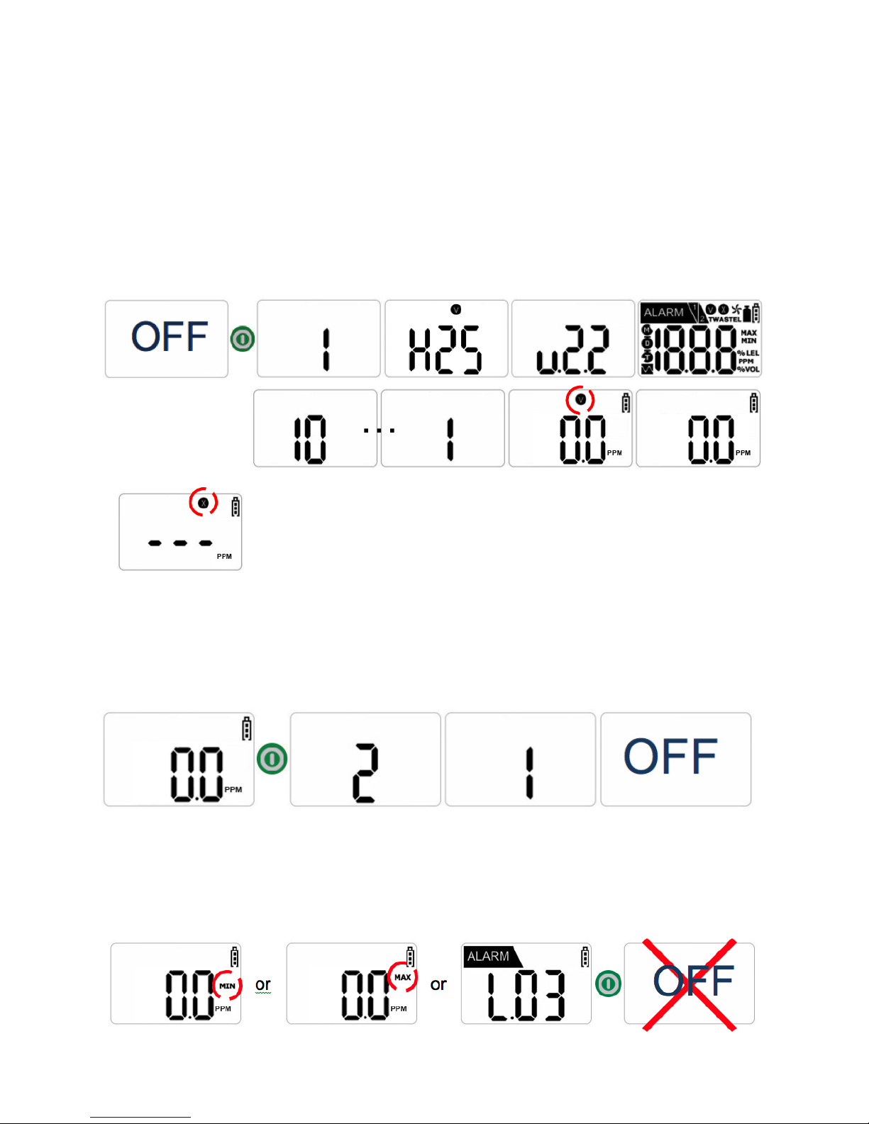
To power on the device, press and hold the green power button for approximately three
seconds.
When powered on, the device will vibrate, flash, and sound an audible alarm to verify
that those features are active. After a 10 second countdown, a “V” icon will flash on the
display screen and the current level of measured gas in ambient air will be shown.
When in Gas Detection Mode (Normal Operating Mode), the “V” icon will disappear
(after blinking several times).
NOTE: In the event that stabilization of the device fails, Gas
Measure Mode will not be entered. Instead, a blinking “X” will
appear on the display screen. The “X” indicates that calibration
of the sensor, or aftercare of the instrument, is required.
Power Off
!
To power off the device, press and hold the green power button for approximately three
seconds. The display screen will countdown the number of seconds remaining until the
device is “OFF.”
NOTE: If the green power button is pressed while the device is not in Gas
Measure Mode, or if the green power button is not held down for the required
amount of time for powering off the device, the device will remain on.
!
!
8!
Basic Operation
NOTE: Appropriate calibration of the device is required prior to operation.
Always ensure that the device makes the proper detection response to the
pertinent gas. Verify that foreign materials that could interfere with the detection
of gas are not blocking the area where gas is to be detected.
Gas Measure Mode
Gas Measure Mode is the normal operating mode of the OI-315.
When in Gas Measure Mode, the concentration of gas and remaining
battery life are displayed on the screen.
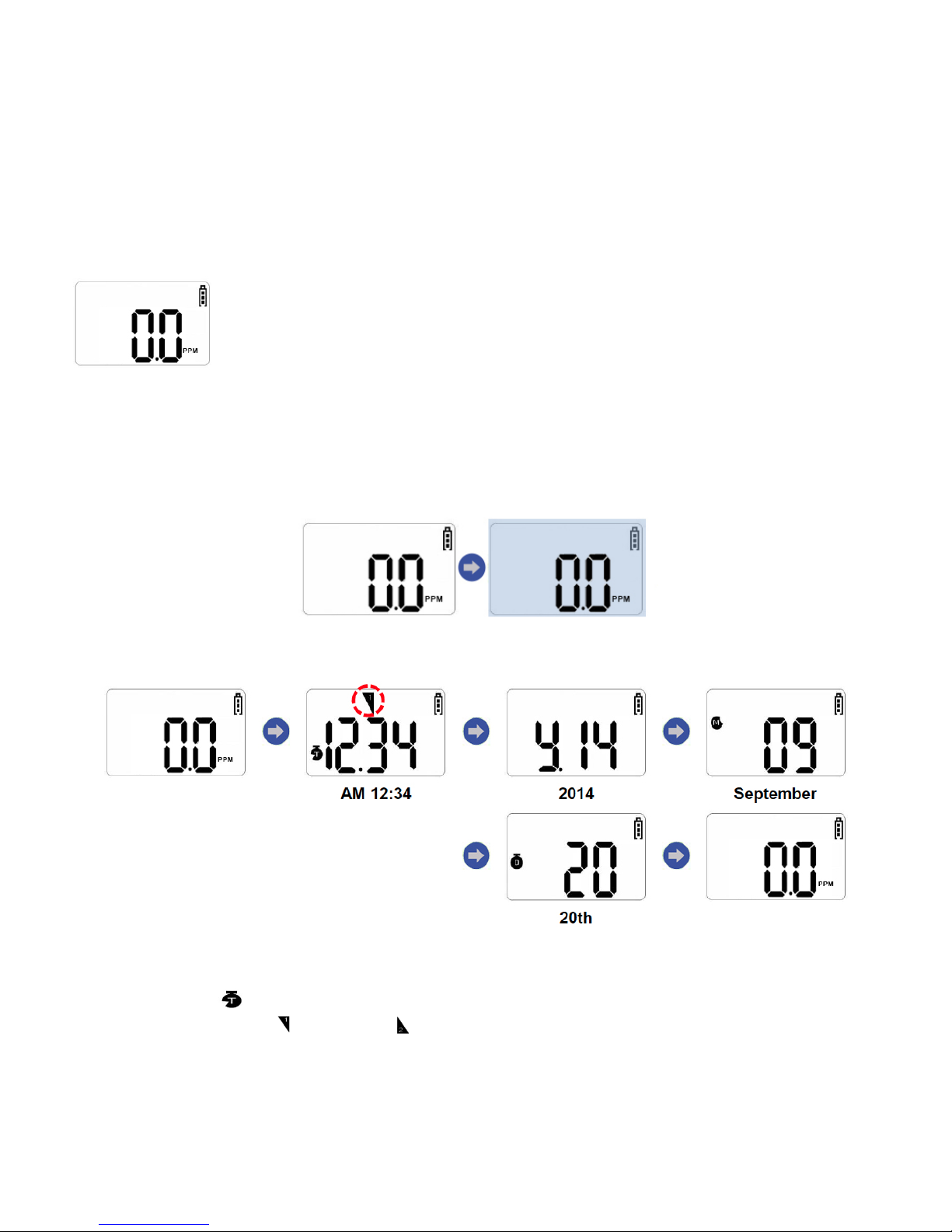
LCD Backlight On/Off
!
To turn on the LCD backlight, press the blue arrow button while in Gas Measure Mode.
To turn off the LCD backlight, press the blue arrow button again (or wait approximately
25 seconds for the backlight to turn off automatically).
Viewing Date and Time
1. Press and hold the blue arrow button for three seconds (while in Gas Measure
Mode).
2. When the icon is displayed on the screen, quickly press the blue arrow button.
The preset time ( = a.m. and = p.m.), year, month, and day are sequentially
confirmed (displayed with the icon or character equivalent of it) with each
additional press of the blue arrow button.
3. Press the green power button to return to Gas Measure Mode (or wait several
seconds for the device to automatically return).

!
!
9!
Setting Date and Time
1. Press and hold the blue arrow button for three seconds (while in Gas Measure
Mode).
2. When the icon is displayed on the screen, press and hold the green power
button for five seconds. The Date and Time Set Mode is displayed and a number
will flicker.
3. Press the blue arrow button to change the value (to increase the value quickly,
hold down the blue arrow button).
4. Press the green power button to save the value that is displayed on the screen and
proceed to the next display.
NOTE: The year value cannot exceed “2030.“

!
!
10!
Setting Alarms
1. Power off the device.
2. To enter Alarm Set Mode, press and hold the blue arrow button for
approximately two seconds. The device will enter 1st Alarm Set Mode.
3. To change the Low Alarm setting, briefly press the green power button. The
display will indicate the current three-digit Low Alarm setting and the first digit
will flash. Press the blue arrow button to increase the digit by one (per press).
NOTE: Each unit value can be set between “0” and “9.”
4. Once the desired value is displayed on the screen, press the green power button to
save the alarm value (and move to the 2nd Alarm Set Mode). Repeat these steps
for the High Alarm.
5. To return to Gas Measure Mode, press the blue arrow button once.
!
Default Alarm Set Points
Gas
O2
CO
SO2
H2
H2S
Cl2
NH3
NO2
1st
19%
30 ppm
2 ppm
100 ppm
10 ppm
.5 ppm
25 ppm
3 ppm
2nd
23%
60 ppm
5 ppm
500 ppm
20 ppm
1 ppm
35 ppm
5 ppm
TWA
N/A
30 ppm
2 ppm
N/A
10 ppm
.5 ppm
25 ppm
3 ppm
STEL
N/A
200 ppm
5 ppm
N/A
15 ppm
1 ppm
35 ppm
5 ppm

!
!
11!
Alarm Displays
Alarm Indicators
If the concentration of gas changes, the value of concentration will be indicated on the
display screen in real-time. If the gas concentration exceeds the present value for the
low or high alarm, the measured value of gas and or icon (respectively) will
blink periodically. In addition, an LED notification, audible alarm and vibration will be
triggered.
Returning to Normal Operating Mode Following a Low Alarm
To silence the audio alarm briefly while in Low Alarm, press the green power button
(the lights and vibration will continue until the reading drops below the Low Alarm
limit). Once the device has been moved to a clean-air location, the alarms will stop.
To remove the alarm icon from the display screen following a Low Alarm, press the
green power button. This step allows the user to confirm that the area is indeed safe.

!
!
12!
Returning to Normal Operating Mode Following a High Alarm
When a High Alarm has been triggered, the audio alarm cannot be silenced and the
alarm icon cannot be removed form the display screen by pressing the green power
button. To remove the alarm following a High Alarm, the unit must be moved to a
clean-air location and power must be cycled (see the Power Off / Power On sections of
this operation manual).
Indication of Peak Value and STEL / TWA Value
When a STEL (Short Term Exposure Limit) / TWA (Time Weighted Average) Alarm
has been triggered, it is indicated with the or icon (respectively), value of
the measured gas, an LED notification, audible alarm and vibration.
To remove the alarm following a STEL / TWA Alarm, the unit must be moved to a
clean-air location and power must be cycled (see the Power Off / Power On sections of
this operation manual).
NOTE: All alarm values are set according to the alarm standard of gas (that is
required by international standards). Therefore, alarm values can be changed
only under the responsibility and approval of the administrator of the work site
where the instrument is used.
The maximum value, STEL value, and TWA value will be displayed consecutively
while in Gas Measure Mode.
Battery Notifications
When the battery level is low (one bar remains on the battery icon), an alarm will sound
repeatedly at five minute intervals. When the battery is nearly exhausted, a unique
combination of audible, LED, and LCD backlight alerts will display for approximately 10
seconds (before the unit turns off completely).

!
!
13!
Data Logging (Alarm Data)
1. Press the green power button four times while in Gas Measure Mode (Data Log Mode is
displayed after minimum, maximum, STEL, and TWA readings).
NOTE: If an alarm event has not yet been recorded on the device, the Data Log
Mode screen will not appear. Instead, the device will return to Gas Measure
Mode following the final green power button press.
2. Press the blue arrow to enter Data Select Mode. In this mode, data is selected and
a record is confirmed.
3. Press the green power button to confirm the year, month, day, time and alarm of
the recorded event.
4. To return to the Data Select Mode, press the blue arrow button while the year,
month, day, and time are shown on the display screen. To return to Gas Measure
Mode, press the green power button.
EXAMPLE: In the reading “L.03” the “L” indicates Log and “03” indicates the
number of data. Therefore, in the reading “L.03” there are three events that have
been logged.
In Data Select Mode, with “01.1” displayed on the screen, “01” indicates the data
instance and “1” indicates the type of alarm that occurred (1 = Low Alarm, 2 =
High Alarm). Therefore, in the three instances of data that occurred, the first
instance was of a Low Alarm.

!
!
14!
To view the second, third, etc. sets of recorded data, press the blue arrow button.
After the last data reading has been displayed, press the blue arrow button to
return to Gas Measure Mode.
NOTE: Up to 20 data events can be stored on a device. Once 20 events are
stored, data is removed automatically in the order that it was received (starting
at Event 1).
Fresh Air Calibration
NOTE: Initial calibration is performed on all devices prior to shipment. Once
received, calibration should be performed monthly (or quarterly) depending on
frequency of use.
NOTE: Calibration should be performed in a fresh-air environment that is free from
any influence of other gases (since calibration is assumed to be performed in an
environment with a concentration of 20.9% Oxygen). It is also recommended that
calibration be performed in a space that is not enclosed.
1. To enter Fresh Air Calibration Mode, press and hold the blue arrow button. While
holding down the blue arrow button, quickly press and hold the green power button.
After approximately three seconds, the display screen will show “CAL” and a
icon will appear and flash.
2. Press the green power button to begin calibration. When calibration begins, a
countdown (starting at 10) will appear on the display screen. Once completed, a “V”
icon will blink several times on the display screen (as shown circled in red below).
Then, the device will return to Gas Measure Mode.
NOTE: If the device fails to enter Calibration
Mode, an “X” icon will appear on the display
screen. If this continues, please contact the
sales representative of this product.
!
!
15!
Standard Gas Calibration
NOTE: Initial calibration is performed on all devices prior to shipment. Once
received, calibration should be performed monthly (or quarterly) depending on
frequency of use.
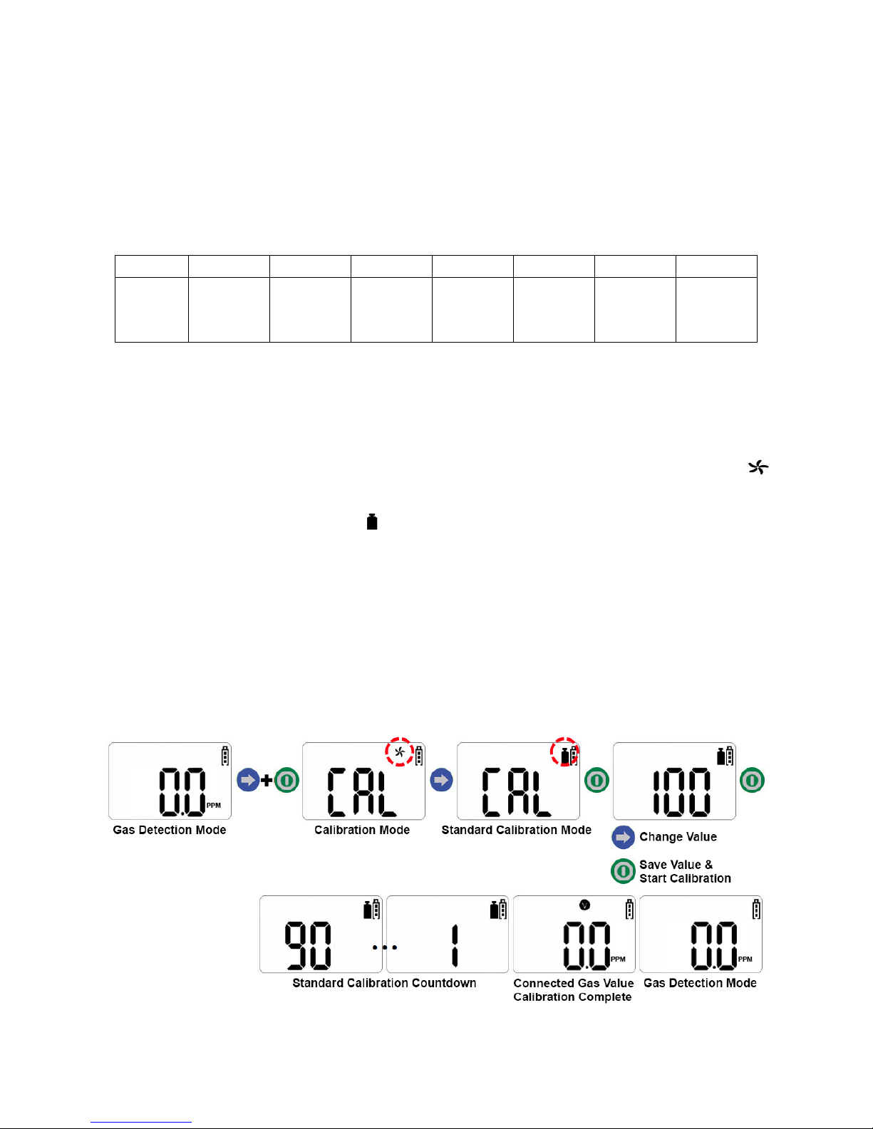
Pre-Set Concentration of Calibration Gas
O2
CO
SO2
H2
H2S
Cl2
NH3
NO2
0%
100
ppm
10
ppm
500
ppm
50
ppm
10
ppm
50
ppm
10
ppm
1. To enter Standard Gas Calibration Mode, press and hold the blue arrow button. While
holding down the blue arrow button, quickly press and hold the green power button.
After approximately three seconds, the display screen will show “CAL” and a
icon will appear and flash.
2. Press the blue arrow button. A icon will appear.
3. Press and hold the green power button for several seconds. The current calibration
gas value will appear on the display screen. Press the blue arrow button to change the
value to match the calibration gas (if necessary).
4. Press the green power button to save each of the three values and start calibration. A
90 second countdown will begin. If the calibration is normally executed, the
concentration value of the connected gas is indicated on the display screen with a “V”
icon.

!
!
16!
5. Disconnect the calibration gas. The device will return to Gas Measure Mode (the
display screen will indicate the current concentration of gas and the remaining battery
life of the device).
NOTE: If the device fails to enter Calibration
Mode, an “X” icon will appear on the display
screen. If this continues, please contact the
sales representative of this product.

!
!
17!
Battery Replacement
When the battery level is low (one bar remains on the battery icon), an alarm will sound
repeatedly at five minute intervals. When the battery is nearly exhausted, a unique
combination of audible, LED, and LCD backlight alerts will display for approximately 10
seconds (before the unit turns off completely).
Required Items:
•Phillips-head Screwdriver
•Replacement Battery = SB-AA02 (Lithium ½AA Battery, 3.6V/1.2Ah)
NOTE: Replacement of the battery in dangerous regions with potential for
explosion is strictly prohibited. Replacement of components can hinder intrinsic
safety function.
NOTE: Replacement battery kits should be purchased from the same retailer
that the device was originally purchased from.
NOTE: The device must be recalibrated following battery replacement.
NOTE: Before disassembling, power off the device according to the instructions
in this operation manual.
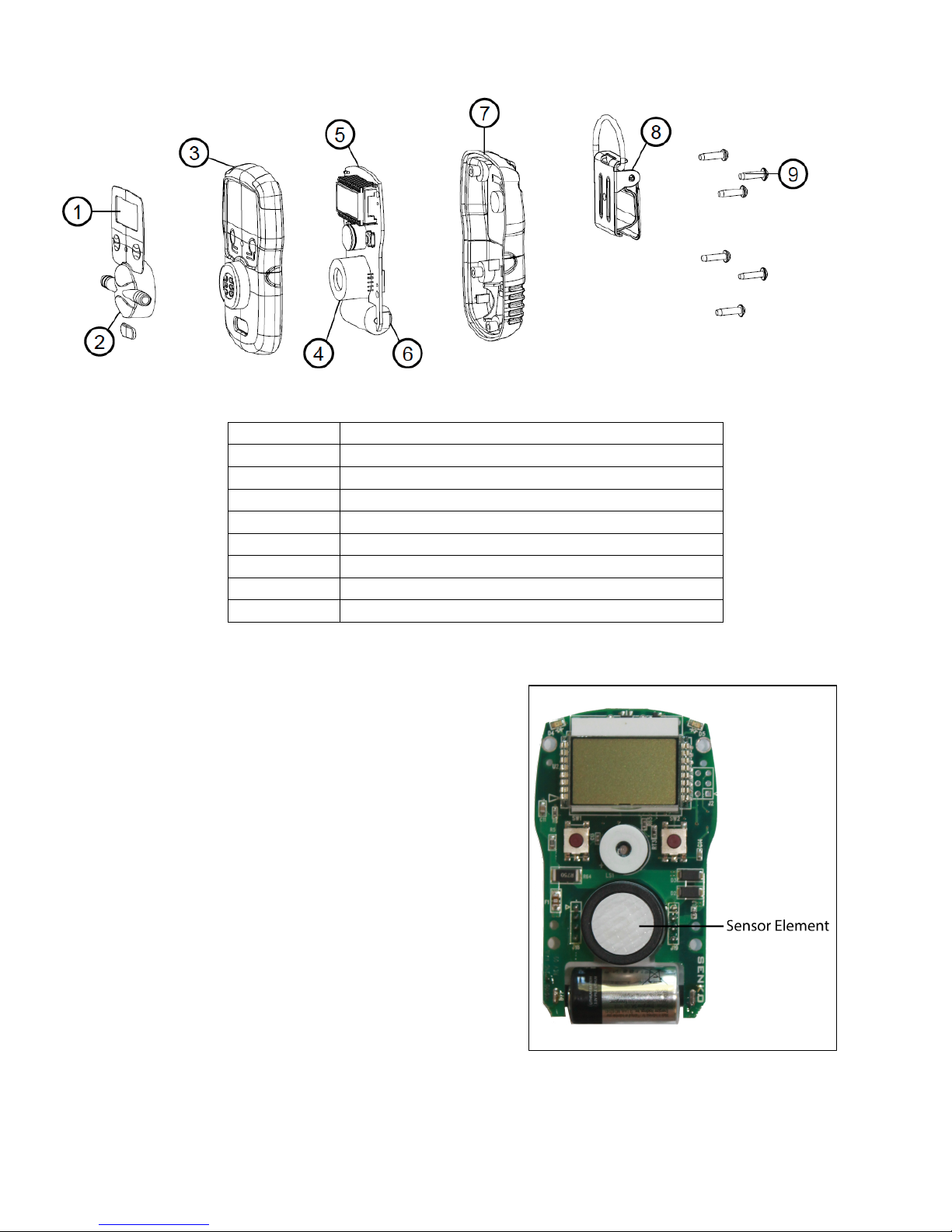
1
Label
2
Calibration cap
3
Front cover
4
Sensor element
5
PCB (terminal board)
6
Battery
7
Rear cover
8
Belt clip
9
Machine screw

!
!
18!
1. Remove the five machine screws located on the rear cover of the device.
2. Separate the rear cover from the front cover by gently pulling them away from
each other.
3. Using your thumb and forefinger, pull the battery out of the terminal board.
4. Slide a new battery into the terminal board.
5. Verify that the “+” and “-” sides of the battery are facing the correct direction
(and touching the battery contacts on the terminal board).
6. Place the front and rear covers together, then replace the five machine screws.
Sensor Element Replacement
Sensor replacement is recommended every two years (or whenever the “X” icon appears on
the display indicating that either the automatic sensor test on start-up, or the “fresh air”
calibration process, has failed).
Required Items:
•Phillips-head Screwdriver
•Replacement Sensor Element = Senko SS series
•Replacement Filters
NOTE: Replacement of components can hinder intrinsic safety function.
NOTE: Replacement sensor elements should be purchased from the same
retailer that the device was originally purchased from.
NOTE: The device must be recalibrated following battery or sensor element
replacement.
NOTE: Before disassembling, power off the device according to the instructions
in this operation manual.
!
!
19!
1. Remove the five machine screws
located on the rear cover of the device.
2. Separate the rear cover from the front
cover by gently pulling them away from
each other.
3. Carefully separate the PCB (terminal
board) from the front cover.
4. Using your thumb and forefinger, gently
pull the sensor element off of the
terminal board.
5. Align the sensor element prongs of a
new sensor element with the eyelets on
the terminal board. Slide the senor
element into place.
6. Place the terminal board back into the
front cover.
7. Place the front and rear covers together, then replace the five machine screws.
1
Label
2
Calibration cap
3
Front cover
4
Sensor element
5
PCB (terminal board)
6
Battery
7
Rear cover
8
Belt clip
9
Machine screw

!
!
20!
User Notice
The OI-315 should be used
in
the
r
ange of
the
applicab
le
t
e
mperatur
e
,
humidity
and
pr
ess
ur
e
that
ar
e
listed in the
Specifications section of this operation manual
.
U
sing
the
device
bey
ond
thi
s
r
ange
may
cause the device to malfunction.
Gas
conc
e
ntr
a
t
ion meas
ur
e
m
e
nt
s
by
the
sens
or ca
n v
ary accor
ding
to
the
envi
r
onme
nt
(t
e
mperatur
e
,
pr
ess
ure
and
humi
di
ty). Ther
ef
or
e, cali
brat
ion of
the
OI-315 s
ho
uld
be
per
f
orm
ed
in
the
same
(or
si
mi
l
ar)
envi
r
onme
nt
of the device’s actual use.
If the temperature changes sharply during use of the instrument (e.g., indoo
rs
vs.
ou
t
do
ors), the
value of
the
meas
ur
ed gas
conc
e
ntrat
ion
can
suddenl
y change.
Please use the
OI-315 af
t
e
r
the
gas
conc
e
ntrat
ion value has s
tabil
ized
.
Seve
r
e vi
brat
ion
or
s
hock
to
the
device
may
cau
se
a
sudden reading change.
Pl
ease use
the
OI-315
af
t
e
r
the
value of gas
conc
e
ntrat
ion has s
tabil
ized
.
Excessive s
hock
to
the
OI-315
can
cause the device and/or sensor to malfunction.
Approval Label Notes
CE marking: Electromagnetic Compatibility
(Directive 89/336/EEC)
Explosion Protection
(Directive 94/9/EEC)
KS marking: Korean Gas Safety for
Explosion Protection
This device is intended to be used in hazardous
area Zone 0 within a temperature range of
-20 C to +50 C, where gases of explosion
group IIC and temperature class T4 may be
present.
S/N: Serial Number
SENKO
0575
DNV A EX
ia
II 1 G
K -GA2BO-
--20C≤Ta≤+50C
nin Onl as in insi saf f use
in dous l ion ead manual i
use
NKO Ltd
oad Oeso Oes -don
Osan- yeonggi- - Sou K ea
S/N:
Table of contents
Other OTIS Gas Detector manuals


