Duomo BX150 User manual


BX150 Fascia
21453
91076845Ph N
ON
213
Test
Reset
%LEL
ppm 120 200 300
813 20
Power Battery
Pre Alarm Alarm
Gas CO
Battery
Sensor
Over Load
Fault
BX150
DUOMO
Key
1. Power On - Lights when supply voltage is applied.This light flashes during self diagnostics start up.
2. Battery - This lights when the BX150 is being powered by the standby battery.When this light flashes the standby battery has low charge.
3. Gas Level Indicators - Displays current level of gas detected*.
4. Pre-alarm LED - These lights indicate the level of gas sensed.8 - 13 - 20% LEL and 120 - 200 -300ppm.
5. Main Alarm - 20% LEL concentration of gas detected.Main alarm relay actuated.
6. Explosive - This lights when the internal DIP switch for explosive gas is moved to the gas position.
7.Toxic Gas - This lights when the internal DIP switch for carbon monoxide is moved to the carbon monoxide position.
8. Fault - Indicates a short circuit, sensor fault, loss of signal or incorrect connection of the sensor.
9. Over Load Sensor - Short circuit or high current absoprtion in the sensors.
10. Over Load Battery - Battery not connected properly or anomalous voltage consumption.
11.Test - When pressed checks the sequence and function of the BX150.
12. Reset - Press this to reset the detector after an alarm or sensor fault condition.
13. Switches - These are used to turn the sensor on/off, determine the type of gas to be sensed, to turn the intrinsically safe option on and off
and alter the alarm actuation.
14. Signal Terminal Block - Sensor terminals.
15. Power Terminal Block - Power terminals.
1
3
4
6
11
12
2
5
7
8
9
10
14
13
15
Overall Dimensions
Test
Reset
%LEL
ppm 120 200 300
813 20
Power Battery
Pre Alarm Alarm
Gas CO
Battery
Sensor
Over Load
Fault
BX150
DUOMO
48mm 120mm
110mm
96mm
96mm
91mm
w: www.duomo.co.uk - e: [email protected].uk - t: 01905 797989 - f: 01905 774296 | ©Duomo (UK) Ltd.2007
46mm
93mm
Cutout Dimensions

5
43
21
3
2
1
12 V
Battery
Sensor
8
7
6
5
Ph 4N 109
Ph
N
System
Fault
Relay Main
Alarm
Relay
Pre-Alarm
NC NC NC
C
C
C
NO NO
NO
Fuse
230V AC Voltage
8109
Relay Main
Alarm
NC
C
NO
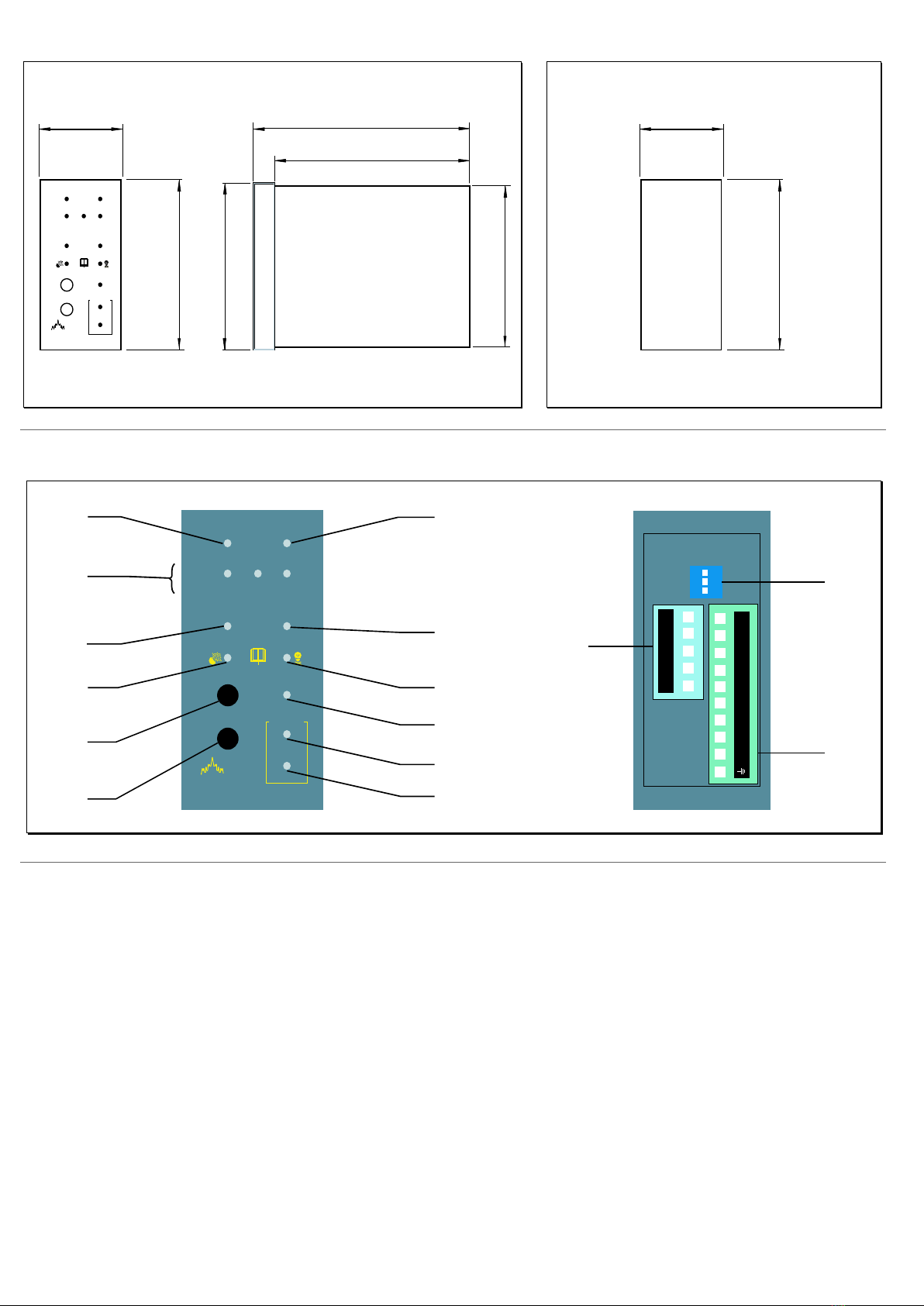
Electrical Installation Installing A Sensor
The BX150 is a safety device designed to give audible alarms
and automatically provide latched electrical isolation of
associated gas safety shut off valves in the event of a gas leak or
build up of toxic gases. The sensor can be located up to 100m
from the gas detector. Cable size should be 1mm2 CSA. If the
sensor cables are run seperately in specific conduit it is not
essential to use screened cable but if the cables are routed
through conduit or trunking containing other wiring the use of
screened cable is advisable.The wiring should be performed by
a qualified person in accordance with current regulations. The
plug-in terminal rail makes installation easy and quick. Do not
mou nt close to any heat source or in an area where moisture is
likely to effect operation. The IP rating of this unit is IP44.
Sensors should be positioned as shown below. If you require
any guidance on this please call our technical help on 01905
797989.
The sensors must be mounted as shown below with
the sintered head pointing vertically down. When
replacing sensors never seperate a sensing head from
its PCB. The sensor will have been calibrated using
this particular board and therefore will not function
correctly with any other.
Important Notes
Always check the wiring before powering up the
system.
Do not test this sensor with anything other than
Duomo test gas (see 'BX150 Operation' section for
further information). Concentrations above this will
damage the sensor and shorten sensor life. The
installation of this gas detector does not release the
user from observing all the regulations concerning
the characteristics, installation and and the use of gas
appliances; the ventilation of the environment and
the elimination of combustion products in
accordance with the local recommendations,
regulations and bylaws. For any damage caused to
people, property or animals resulting from incorrect
connection, installation or application of this gas
detector Duomo will not be held responsible or liable.
To ensure correct function after installation Duomo
provide a commissioning service using calibrated test
gases. For this service call 01905 797989.
SGM595
autosetting
ON
SGM595
autosetting
ON
SGM595
autosetting
ON
300
1600
300
Natural Gas
Carbon
Monoxide
L.P.G.
Typical Wiring Schematic for BX150
Signal Terminal Block
Power Terminal Block * Intrinsic Safety
switch on
8
7
6
5
Ph 4
N109 5
4
3
2
1
3
2
1
12 V
Battery
Power Supply Unit
(If required)
12V
(Volt-free relays -
Link to energise)
(Optional standby
battery - If required)
w: www.duomo.co.uk - e: sales@duomo.co.uk - t: 01905 797989 - f: 01905 774296 | ©Duomo (UK) Ltd. 2007
12V Supply Typical
Configuration
230V Supply Typical
Configuration

Y
ConfiguringTheBX150
Exampleshowsexplosivegassetting
ExampleshowsIntrinsicSafetyon
Exampleshowsdetectorconfiguredforalatchingmainalarm
The BX150 has a DIP switch on the rear panel. Switch 1 is used to control the main alarm delay. Switch 2 is used to
configurethemain alarm latching mode.Switch 3isused to select whether theunit detectstoxicorexplosivegases.
TheBX150can beconfigured to provideseveral modesof operation.Theconfigurableparametersare:
Switch3 ontheDIPswitch
Typeof gasto besensed.TheseareGASor CO.Thesymbolson thefront fascia
of the detector are EN standard symbols and refer to any explosive or toxic
gas.If toxic gas,e.g.carbon monoxide isto be sensed on a given zone move
theswitch to theOFFposition.If explosive,e.g.natural gas,LPG,hydrogen etc.
movetheswitch totheONposition.
Switch1 ontheDIPswitch
Intrinsic safety determines the condition of the main alarm relay and hence
the operation of the gasvalve.When it is'ON' the relay isin a normally open
state.When it is'OFF' therelay isin anormally closed state.NOTE:Thisaffects
how thegasvalveoperatesand meansthat you may need to changehow it is
wired totheBX150.
Switch2 ontheDIPswitch
Main alarm relayactuation method.Thiscan beconfigured to provideeither a
latching or atemporary alarm operation.When the main alarm isactuated in
an alarm condition if theswitch isin the 'ON' position the relay will remain in
thisposition even after theconcentration of gashasreduced below thealarm
threshold.If theswitch isin the'OFF' position themain alarm relay will actuate
for 60 secondsand then if thelevel of gashasdropped will return to thevolt-
free main alarm relay to the running condition.The indication on the panel
fascia and the audible alarm will still indicate main alarm. This mode of
operation is used when using manual reset gas valves and battery back-up
systemsfor extending standbybatterylife.
GasSensed
MainAlarm relay
Reset Pressed
GasSensed
MainAlarm relay
Reset Pressed
1minute Time
Mainalarmswitch in'OFF'position Mainalarmswitch in'ON'position
ON
21
ON
21
20" C
ON
2
3
3
31
w:www.duomo.co.uk - e:sales@duomo.co.uk - t:01905797989 - f:01905774296 | ©Duomo(UK)Ltd.2007

BX150 Operation
Before powering up the BX150 once again check that all electrical connections are correct.
1. Apply power using the proper external switch.This switch should be fitted with protection fuses.
2. All of the lights on the fascia will light up in turn.This will take approximately 20 seconds.This checks the function of all
the LED's.
3. The ON LED will remain flashing for about 90 seconds. This is the sensor warm-up period. The gas detector will not
provide gas detection during this period.When the ON light becomes constant the detector is in operation.
4. By pushing and maintaining pressure on the manual TEST button a function test can be performed.
The sequence will be:
a) The 8% LEL / 120ppm LED will be actuated.
b) The 13% LEL / 200ppm and the pre-alarm LED will be actuated.The pre-alarm relay will be changed over and the buzzer
will then issue a low frequency sound.
c) The 20% LEL / 300ppm and main alarm LED will be actuated. In addition to keeping the pre-alarm relay switch on, the
main alarm relay will be changed over. The alarm LED will light to show that the system is in alarm and the buzzer will
issue a higher frequency sound.
By releasing the the manual TEST button the lights will go out and the audible alarm will cease. If a latched alarm
function on the main relay is configured this will remain on until the RESET button is pressed.
5. In order to conduct a full function test it is essential to use Duomo or equivalent calibrated test gas. The maximum
concentrations are;
- 40% LEL for methane in air
- 350ppm for carbon monoxide
- 0.85% (MOL) for propane
Any higher than this can reduce sensor life.NOTE: NEVER TEST USING NEAT GAS.THIS WILL POISON THE SENSOR.
6. To simulate a sensor fault situation disconnect the sensor plug.The detector will go into a FAULT alarm and the sensor
fault relay will be actuated.
The control unit will then carry out the following:
a) The FAULT and MAIN ALARM LED's will light up and blink
b) The buzzer will issue a continuous sound
c) The FAULT and MAIN ALARM relays will switch.
Reconnect the return cable and press RESET to restore the control unit functioning.
Maintenance Procedure
This detector must be function checked as described above using calibrated test gas every 6 months. To arrange for a
Duomo engineer to conduct this work or to arrange a service contract please call 01905 797989.
w: www.duomo.co.uk - e: [email protected].uk - t: 01905 797989 - f: 01905 774296 | ©Duomo (UK) Ltd. 2007

Troubleshooting
If you are experiencing difficulties, having made the checks listed above call Duomo on 01905 797989 for
technical assistance.
The Problem The Solution
The device does not start up Check that the 230V mains power is correctly
connected. If powered by the battery, check that the
12V DC power is correctly connected.
The FAULT LED lights up
The OVERLOAD SENSOR LED lights up
The OVERLOAD BATTERY LED lights up
The control unit is repeatedly issuing an alarm
The control unit is issuing an alarm and does not
shut off the devices connected to it
Check that the connecting cables from the BX150 to
the sensors are intact, that the sensors are properly
powered and that the signal cable is correctly
connected.
Check that there are no gas leaks. If the alarm signal
and the FAULT indicator light turn on together, check
the sensor.
Check that;
- the power polarity has not been inverted
- that no short-circuit is present
- that the probes were not damaged during
installation, that no excessive current absorption
is present
Check that the connection cables are not
shortcircuited, that the polarity has not been
inverted and that the battery is not damaged.
Check that the wiring is correct and that the DIP
switch has been set properly. All relays must be free
from electrical power. Check the drawing of the
connections.
A 12V DC solenoid valve, which does not work well, is
connected to the BX150
Direct connection of 12V DC solenoid valves or sirens
to the BX150 is not permitted. An external power
unit must always be used. The BX150 gives a
maximum current of 50mA.
In case of alarm
Extinguish any naked flames.
Do not switch lights or electrical devices on or off.
Open all windows and doors to increase ventilation.
If the 'ALARM' LED is off the levels of gas have dropped. A responsible, qualified person is now safe to find the cause of
the alarm.
If the alarm sound remains constant, and the cause is not evident or possible to eliminate turn off the emergency
isolation valves to the area and contact your gas provider emergency line.They will advice accordingly.
w: www.duomo.co.uk - e: [email protected].uk - t: 01905 797989 - f: 01905 774296 | ©Duomo (UK) Ltd. 2007

Technical Specification
Power Supply230V AC 50Hz +/- 10%
Secondary Battery12V DC +/- 10%
Power Consumption9W maximum @ 230V / 2.5W maximum @ 12V
Relay contact range10A resistive
Pre-alarm 13% LEL / 200ppm
Main alarm 20% LEL / 300ppm
Sensor faultShort circuit, interruption, sensor deterioration
No. of remote sensors1
Input signal4 - 20mA
Device precision 1% FS
Microprocessor8 bytes
Working temperature-10 °C to 40 °C
Maximum distance for sensor connection100m
Cable diameter for sensors1mm2 CSA
Dimemsions48mm x 96mm x 110mm
Protective ratingIP42
Commissioning
It is strongly recommended that this detector should be commissioned by Duomo Commissioning Engineers or
engineers approved by Duomo to carry out this work. A quotation for commissioning or service will be provided upon
request. Fax site details and preferred date for commissioning to 01905 774296 and the Duomo Service Department
will fax back confirmation.
The benefits of this equipment being commissioned by Duomo are:
On board spares. If for whatever reason this equipment doesn't function correctly Duomo engineers will have spares on
board to ensure that the commissioning is successful.
A Duomo Commissioning Certificate is provided.
It is prudent to make electrical connection to the detector terminal plus when withdrawn and leave the plug off the
detector so that the Duomo Engineer is the first to power up the unit on site. This allows wiring to be checked prior to
commissioning and avoids damage due to incorrect connection. Guarantees for this product will become void if
damage is caused by the installer.
w: www.duomo.co.uk - e: [email protected].uk - t: 01905 797989 - f: 01905 774296 | ©Duomo (UK) Ltd. 2007
Other manuals for BX150
1
Table of contents
Other Duomo Gas Detector manuals
Popular Gas Detector manuals by other brands

FORENSICS DETECTORS
FORENSICS DETECTORS FD-60 user manual

Seitron
Seitron RGY 000 MBP4 Operation, installation, and maintenance manual

HSS Hire
HSS Hire Safe and Sure 34074 Operating & safety guide

RKI Instruments
RKI Instruments GX-3R Pro Operator's manual

iCeeO2
iCeeO2 500P instruction manual

GEV
GEV FMG 1275 user manual

SARAD
SARAD Radon Scout Home manual

Trotec
Trotec BG30 operating instructions

Greystone Energy Systems
Greystone Energy Systems CDD Installation and operating instructions

FORENSICS DETECTORS
FORENSICS DETECTORS FD-90E-RED Operation manual

Dräger
Dräger X-am 3500 Instructions for use

GASTRON
GASTRON GTD-2000Ex instruction manual