Figaro EC01 User manual

取扱説明書
Instruction Manual
EC01
(Test chamber for gas sensor evaluation)
Instruction Manual
1. Safety instructions
2. Precautions for use
3. Parts names and functions
4. Measurement preparation
5. Measuring procedure
6. Specifications
Table of contents
Thank you very much for purchasing EC01 (Test chamber for gas
sensor evaluation). Please read this instruction manual carefully to use
the product correctly.
Page
1
1
2
4
6
8
Figaro Engineering Inc.

取扱説明書
Instruction Manual
(1)
(2)
(3)
(4)
1. Safety instructions Make sure to follow
2. Precautions for use
This product is a simplified test chamber. Make sure to close the lid firmly without any gaps.
For highly accurate gas testing, use more airtight test chambers than this product.
Placing large-volume equipment such as gas detectors in the test chamber reduces the
effective volume of the test chamber, and may lead to errors in the gas concentration.
Highly adsorbent gases such as ammonia, VOCs and organic solvent vapors attach to the
inner surface of the test chamber easily, and are therefore not suitable for such applications.
If the gas is adsorbed in the chamber and liquefied, the concentration of the gas in a
gaseous state may decrease. If you need to test with highly adsorbent gases, use a test
chamber made of a material resistant to gas adsorption or with an internal coating.
If highly adsorbent gases are injected into the test chamber, remove adsorbed gases by
appropriate measures such as cleaning the inside of the test chamber with alcohol and
venting the inside with clean air for a long time.
Measurements in high / low temperature or in extremely high / low humidity in indoor
environments may affect the measurement values of the gas sensor. Check the
specification of each sensor.
- 1 -
This test chamber is not explosion-proof. Do not use it for measurements when using
flammable gases with greater than 50% concentration of the Lower Explosive Limit (LEL).
The test chamber does not guarantee a completely sealed condition. Do not use it for
measurements with high concentrations of toxic gases hazardous to the human body.
When measuring with flammable gas, make sure to handle flames with caution, and only
exhaust gas from the test chamber in an area with adequate ventilation. Also be sure to take
necessary safety precautions such as installing gas detectors.
Perform measurements in a well-ventilated area, especially when using toxic gases. Also,
be careful not to inhale gases when venting them from the test chamber. Make sure to
ventilate gases outdoors or in fume hoods for safety.
(1)
(2)
(3)
(4)
(5)

取扱説明書
Instruction Manual
* Make sure that the test chamber for gas sensor evaluation itself and the following accessories
are included in the package
Test chamber for gas
sensor evaluation
(with signal cable)
Lid Syringe (5ml)Test board for
evaluation modules
③
①Test chamber body
②Control box
③AC power cable
④Power switch
⑤Switch of mixing fan
⑥Mixing fan
⑦Power supply cable
⑧Ribbon cable for measuring sensor output
(50-core)
⑨Supply voltage adjustment hole
(not used normally)
⑩Test chamber lid
⑪Gas inlet
* Adhesive tape is affixed to the syringe insertion rubber.
Do not remove this tape, because it is used to prevent the
insertion rubber from coming off when removing the syringe
during measurement.
⑫Test board for gas sensor evaluation modules
⑬Connectors for module measurement (CH1 to CH12)
⑭Connector for ribbon cable connection (CN1)
⑮Connector for power supply (CN2)
⑥
④
⑫
⑧
⑩
⑬
⑭
⑮
⑨
⑦
⑤
Instruction Manual
(this document)
②⑪
3. Parts names and functions
Products and accessories
- 2 -
①
Parts names

取扱説明書
Instruction Manual
CN1
Pin
number
Evaluation
module
Connector pin
number
Evaluation
module
CH number
1 to 6 1 Common
VC (5.0 V DC)
7 2 CH18 3
9 4
10 2 CH211 3
12 4
13 2 CH314 3
15 4
16 2 CH417 3
18 4
19 2 CH520 3
21 4
22 2 CH623 3
24 4
25 2 CH726 3
27 4
Connector pin layout for power supply (CN2)
Signal from the test board for evaluation modules (CN1)
CN1
Pin
number
Evaluation
module
Connector pin
number
Evaluation
module
CH number
28 2 CH829 3
30 4
31 2 CH932 3
33 4
34 2 CH1035 3
36 4
37 2 CH1138 3
39 4
40 2 CH1241 3
42 4
43 NC
44 NC
45 to
50 5 Common
GND
Pin number
Name Function
1 VC
Power input
2 GND Ground
* The red line on the ribbon cable line (50-core)
corresponds to number "1" of the CN1 pin.
- 3 -
Connector pin layout for gas sensor evaluation module
Pin
number
Model number of the gas sensor evaluation module
EM26 EM3870A EM5042A
EM5141A
EM-FECS (A)
1 VC VC VC VC VC
2 VOUT
V
OUT1
(CH4)
3
V
OUT2 (CO)
VOUT VOUT VOUT
4
5 GND GND GND GND GND
VC = Power input
VOUT = Sensor output
GND = Ground
* Refer to the Product Information
of each gas sensor evaluation
module for details.
Wiring specifications

取扱説明書
Instruction Manual
4. Measurement preparation
Prepare a measuring instrument (such as data logger
or digital multimeter) that can measure the voltage.
Wire the voltage measuring instrument.
・The measurement device on the right is an example.
Connecting a ribbon cable directly to a data logger or other voltage measuring instrument.
The signal wires coming out of the test chamber for gas sensor
evaluation correspond to connector pins 1 to 50, starting with the
red line. [Example of connection to a
data logger]
(2) Connecting a ribbon cable with a connector from the chamber to an extension ribbon cable
Ribbon cable: Cable with 2.54 pitch (50-core) compatible with a MIL
standard connector
- 4 -
Disconnect the connector by cutting the end of the ribbon cable coming out of the chamber body.
Check “Wiring specifications” on page 3, and connect the required lines to the voltage measuring device.
5V
GND
CH1
CH2
……
CH12
Wiring using recommended connectors prepared by the user
(1) Connecting a ribbon cable with a connector from the chamber to a printed circuit board, etc.
There are two methods for wiring:
Recommended connector: XG4A-5031 (Omron)
Recommended connector: XG4E-5031 (Omron)
1
B
.
A
.

取扱説明書
Instruction Manual
Attach the sensor to the gas sensor evaluation module, and attach it to the test board for
evaluation modules.
Match the pin number of the gas sensor evaluation
module and the terminal number of the connector on the
test board for evaluation modules, and insert it fully.
[Example of attachment of the test board for
evaluation modules]
Insert the terminal of the gas sensor
evaluation module into the larger
hole of the connector for the
module.
1 5
- 5 -
Open the lid of the test chamber and turn on the mixing fan for 2 to 3 minutes to remove
the contaminated air in the chamber.
①Connect the AC power cable of the test chamber to the
power outlet, and turn the power switch on the top of the
control box ("POWER") to "ON".
* The “green LED” in the control box lights up.
Green
LED
②Turn on the “FAN” switch and rotate the mixing fan for 2 to 3 minutes to remove the contaminated air
in the chamber, and stop it when it is done.
Connector for power supply
Connector for ribbon cable
(50-core)
Place the test board for evaluation modules attached with the gas sensor evaluation
modules in the test chamber. Connect the power supply cable and the ribbon cable to
their respective connectors on the test board.
③Set the power switch to “OFF”.
①Set the power switch to “ON”.
②Check if they are properly wired with data logger, for example, in advance.
* If the power supply voltage needs to be adjusted, see “How to adjust the power supply voltage” in page 7.
The factory setting of the supply voltage is 5 V. When testing with our gas sensor evaluation module, the
power supply voltage does not require adjustment.
Check the output voltage.
2
3
4
5
Make sure that the power switch is
“OFF” before connection.

取扱説明書
Instruction Manual
- 6 -
Close the lid of the test chamber.
5. Measuring procedure
The adhesive tape is affixed to the top surface to prevent the
"rubber for syringe insertion" from popping out. Replace it with a
new adhesive tape as it ages.
* Use standard mending tape.
After the measurement is complete, open the lid in a well ventilated area and turn the fan
to vent the gas in the chamber.
When opening the lid after the measurement, make sure to place the test
chamber in a well ventilated area, open the lid and turn the fan to remove the
gas in the chamber. Be careful not to inhale the gas from the test chamber or
spread it into the room.
* The lid should be closed by lightly pressing down to make it airtight.
Before injecting the gas, make sure to measure the output voltage from the evaluation
module in clean air, and confirm the voltage is stable.
Insert the syringe needle into the gas inlet on the lid and inject the gas.
* Calculate the required gas injection volume from the inner volume of the chamber and the gas
concentration to measure. (See below for calculation method)
After the injection, turn on the fan switch and mix the gas for approximately 30 seconds.
Then perform the measurement considering the operating conditions of the sensor.
The injection volume V (ml) of 100% concentration gas required to make a test gas of
concentration C (ppm) in the test chamber can be calculated from the following formula.
1
3
5
2
4
When diluting 100% concentration gas:
V = (chamber capacity) x C
1,000,000
* Chamber capacity = 10,300 ml
Example: Test gas
concentration 100% concentration
gas injection volume
1,000 ppm
5,000 ppm 10.3 ml
51.5 ml
Calculation of the injection volume of the gas

取扱説明書
Instruction Manual
Turn clockwise (+) 4.00V -> 5.50V
Turn counterclockwise (-) 5.50V -> 4.00V
The factory setting of the power supply voltage to the test board is set to 5V, and users do not need
to adjust it usually.
This adjustment should only be made if any adjustment is required between 4.00 V and 5.50 V.
- 7 -
Screwdriver
The power supply voltage can be adjusted by inserting a + screwdriver into the supply voltage
adjustment hole on the side of the control box and turning the adjustment volume.
Check the voltages between ribbon cable connector pin numbers 1 to 6 (VC+) and 45 to 50
(GND).
Control box
How to adjust the power supply voltage

取扱説明書
Instruction Manual
Name Test chamber for gas sensor evaluation
Model number EC01
Product configuration Test chamber body and lid without opening
Test board for gas sensor evaluation modules (12 modules max.)
Syringe (5ml)
Main power AC 100 V to 240 VAC
Power consumption 2W (when fan is on)
* excluding power consumption required for gas sensor operation
Operating temperature
range 0 °C to 50 °C
Effective inner capacity 10,300 ml
External dimensions 340 (W) x 270 (D) x 202 (H) mm (excluding ribbon cable)
Weight Approx. 4 kg (including test board for evaluation modules)
Main material Chamber body: Polyvinyl chloride Lid: Acrylic
6. Specifications
Contact for inquiries about our products:
- 8 -
This manual is subject to change without notice to improve product
performance.
Connectors
Part number
Manufacturer
Standards
CN1 XG4A-5031 OMRON
MIL standard
MIL
-C-83503
UL standard
(File No. E103202) certified
CN2 B2P-VH-1 JST
UL standard
(File no. E60387) certified
CSA standard
LR20812
Evaluation
module
Connectors
(CH1 to CH12)
05JQ-BT JST
UL standard
(File no. E60387) certified
CSA standard
LR20812
Standards of connectors
(Model number: EC-P01)
The following parts are available separately.
Lid with air supply and exhaust openingsTest board for evaluation modules
Optional parts
Board size: 200 x 258 mm Air inlet and outlet, outer diameter:
32 mm Φ
(Model number: EC-P02)
Figaro USA, Inc.
121 S. Wilke Rd. Suite 300
Arlington Heights, IL 60005 USA
TEL.: (1) 847-832-1701
FAX.: (1) 847-832-1705
E-mail: figarousa@figarosensor.com
Table of contents
Other Figaro Gas Detector manuals
Popular Gas Detector manuals by other brands
BEINAT
BEINAT GSH900 Installation and user guide

Tecnocontrol
Tecnocontrol SE296KM quick start guide
Electronics
Electronics Ei413 quick start guide
Blackline Safety
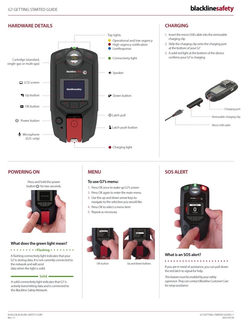
Blackline Safety G7 BRIDGE Getting started guide
Tecnocontrol
Tecnocontrol TS293P Series user manual

Tecnocontrol
Tecnocontrol TS293IM user manual
GASTRON
GASTRON GIR-3000 instruction manual
S&S Northern
S&S Northern Merlin GDP4 Installation, operating and maintenance
Foxcroft
Foxcroft FX-Mini operating manual
GASTRON
GASTRON GTD-3000ExW instruction manual
Consilium
Consilium Salwico ST400 H2S Calibration instructions

Hanwei
Hanwei JL269LED Operation manual
