OTIS GEN II OI-6000 User manual


CAUTION
WARNING –EXPLOSION HAZARD –SUBSTITUTION OF COMPONENTS MAY IMPAIR
SUITABILITY FOR CLASS I, DIVISION 1, OR EQUIVALENT AS STATED IN USER MANUAL
AVERTISSEMENT –RISQUE D’EXPLOSION-LA SUBSTITUTION DE COMPOSANTS PEUT
RENDURE CE MATERIEL INACCEPTABLE POUR LES EMPLACEMENTS DE CLASSE I,
DIVISION
CAUTION: FOR SAFETY REASONS, THIS EQUIPMENT MUST BE OPERATED AND
SERVICED BY QUALIFIED PERSONNEL ONLY. READ AND UNDERSTAND THE
INSTRUCTION MANUAL COMPLETELY BEFORE OPERATING OR SERVICING.
ATTENTION: POUR DES RAISONS DE SECURITE, CET ÉQUIPEMENT DOIT ETRE
UTILISE ENTRETENU ET REPARER UNIQUEMENT PAR UN PERSONNEL QUALIFIE.
ETUDIER LE MANUEL D' INSTRUCTIONS EN ENTIER AVANT D' UTILISER, D'
ENTERETENIR OU DE RÉPARER L' ÉQUIPEMENT.
CAUTION: THIS AREA MUST BE FREE OF FLAMMABLE GASES DURING CALIBRATION.
ATTENTION : CETTE ZONE DOlT ETRE EXEMPTE DE GAZ INFLAMMABLES PENDANT
L'ETALONNAGE.
CAUTION:TO PREVENT IGNITION OF EXPLOSIVE ATMOSPHERES, REMOVE FROM
EXPLOSIVE ATMOSPHERE BEFORE SERVICING
WARNING: A CONDUIT SEAL MUST BE USED WITHIN 18 INCHES OF THE ENCLOSURE
WALL TO COMPLY WITH THE HAZARDOUS LOCATION RATING OF THIS PRODUCT
DANGER
DANGER: OTIS INSTRUMENTS INC. OI-6000-X-X-X-X-O IS AN AMBIENT AIR
HAZARDOUS GAS SENSOR ASSEMBLY AND ONLY MONITORS IN THE IMMEDIATE
VICINITY OF THE SENSOR HOUSING. A SITE SURVEY IS REQUIRED IN ORDER TO
DETERMINE THE BEST PLACEMENT AND QUANTITY OF SENSOR ASSEMBLIES.
IMPROPER INSTALLATION CAN LEAD TO AN UNDETECTABLE GAS LEAK WHICH
COULD RESULT IN PERSONAL INJURY OR LOSS OF LIFE.


TABLE OF CONTENTS
OI-6000-X-X-X-X-O OPS_GUIDE_REV 3.1 i
TABLE OF CONTENTS
1PRODUCT OVERVIEW..........................................................................................................................................1
1.1 INTRODUCTION ....................................................................................................................................................1
1.2 PRODUCT SPECIFICATIONS ...............................................................................................................................2
1.3SYSTEM DIAGRAMS.............................................................................................................................................3
1.3.1 EXTERNAL SYSTEM DIAGRAM ...........................................................................................................................3
1.3.2 INTERNAL SYSTEM DIAGRAM.............................................................................................................................4
1.3.3 ASSEMBLY DIAGRAM...........................................................................................................................................5
2INSTALLATION AND START-UP..........................................................................................................................6
2.1 PRODUCT PLACEMENT .......................................................................................................................................6
2.2 PRODUCT MOUNTING .........................................................................................................................................7
2.3 WIRING CONFIGURATIONS.................................................................................................................................7
2.3.1 OPENING THE ENCLOSURE................................................................................................................................8
2.3.2 CONNECTING POWER.........................................................................................................................................8
2.3.3 CONNECTING 4-20 MA OUTPUT .......................................................................................................................10
2.3.4 CONNECTING RS-485 ........................................................................................................................................12
2.3.5 CONNECTING RELAYS/ALARMS.......................................................................................................................14
2.3.6 CONNECTING THE FAULT TERMINAL..............................................................................................................21
2.3.7 CLOSING THE ENCLOSURE ..............................................................................................................................23
2.4 SYSTEM START-UP............................................................................................................................................23
2.5 NORMAL OPERATING MODE.............................................................................................................................24
3PRODUCT SETTINGS AND CONFIGURATION .................................................................................................25
3.1 RELAY TEST........................................................................................................................................................25
3.1.1 PERFORMING THE RELAY TEST ......................................................................................................................26
3.2 NETWORK ID.......................................................................................................................................................26
3.3 SYSTEM INFORMATION.....................................................................................................................................27
3.4 NULL/CALIBRATION TIMER INFORMATION .....................................................................................................27
3.5 UNIT INFORMATION ...........................................................................................................................................28
3.6 BACKGROUND SETTING....................................................................................................................................28
3.7 LATCHING AND NON-LATCHING RELAY SETTINGS .......................................................................................29
3.7.1 RELAY 1: LATCHING/NON-LATCHING SETTING.............................................................................................29
3.7.2 RELAY 2: LATCHING/NON-LATCHING SETTING.............................................................................................30
3.8 RELAY FAIL-SAFE SETTING ..............................................................................................................................30
3.8.1 RELAY 1: FAIL-SAFE SETTING .........................................................................................................................31
3.8.2 RELAY 2: FAIL-SAFE SETTING .........................................................................................................................31
3.9 CALIBRATION METHOD .....................................................................................................................................32
3.10 MODBUS ADDRESS SETTING...........................................................................................................................33
3.11 MODBUS BAUD SETTING...................................................................................................................................34
3.12 4-20 mA OFFSET SETTINGS..............................................................................................................................35
3.12.1 ZERO OFFSET SETTING....................................................................................................................................35
3.12.2 FULL-SCALE OFFSET SETTING ........................................................................................................................36
3.13 DISPLAY SCREEN CONTRAST SETTING .........................................................................................................36
3.14 RETURN TO FACTORY DEFAULT SETTINGS ..................................................................................................37

TABLE OF CONTENTS
ii OI-6000-X-X-X-X-O OPS_GUIDE_REV 3.1
4OPERATION SETTINGS .....................................................................................................................................39
4.1 POWERING THE DEVICE ...................................................................................................................................39
4.1.1 POWERING OFF..................................................................................................................................................39
4.1.2 POWERING ON ...................................................................................................................................................39
4.2 SENSOR CALIBRATION......................................................................................................................................40
4.2.1 NULLING THE SENSOR (AUTO NULL) ..............................................................................................................40
4.2.2 CALIBRATING THE SENSOR (MANUAL CAL) ...................................................................................................42
4.2.3 CALIBRATING THE SENSOR (AUTO CAL) ........................................................................................................43
4.3 SENSOR ALARM SETTINGS ..............................................................................................................................45
4.3.1 SENSOR LOW ALARM SETTING........................................................................................................................45
4.3.2 SENSOR LOW ALARM RISE/FALL SETTING.....................................................................................................46
4.3.3 SENSOR HIGH ALARM SETTING.......................................................................................................................46
4.3.4 SENSOR HIGH ALARM RISE/FALL SETTING....................................................................................................47
4.4 SENSOR RADIO ADDRESS................................................................................................................................47
4.5 MANUAL RESET FOR ACTIVATED LATCHING ALARMS .................................................................................48
5PRODUCT MAINTENANCE.................................................................................................................................49
5.1 SCHEDULED MAINTENANCE.............................................................................................................................49
5.2 SENSOR REPLACEMENT...................................................................................................................................50
5.3 PRODUCT TROUBLESHOOTING.......................................................................................................................51
5.4 PRODUCT REPLACEMENT PARTS AND ACCESSORIES................................................................................52
APPENDIX A: INTRODUCTION TO 4-20 mA CURRENT LOOP SIGNALS ............................................................................54
APPENDIX B: MODBUS COMMUNICATIONS.........................................................................................................................56
APPENDIX C: MODBUS REGISTER MAP...............................................................................................................................58
APPENDIX D: PRODUCT WARRANTY STATEMENT.............................................................................................................61
APPENDIX E: INFORMATION ABOUT RMA SERVICE REPAIRS .........................................................................................63
APPENDIX F: INFORMATION ABOUT RMA RETURNS FOR CREDIT ..................................................................................65

PRODUCT OVERVIEW
OI-6000-X-X-X-X-O OPS_GUIDE_REV 3.1 1
1PRODUCT OVERVIEW
1.1INTRODUCTION
The Otis Instruments, Inc. (Otis) GEN II Model OI-6000-X-X-X-X-O (OI-6000) Explosion-Proof Ambient Air
Hazardous Gas Detector is designed to detect a wide range of toxic gases in potentially hazardous environments.
This product is CSA certified as Class I, Division 1, Groups C and D and rated for Zone 1, Group IIB. The OI-6000
features non-intrusive magnetic switches that allow for complete system configuration, regular calibration, and
product maintenance to be performed in the field, without opening the enclosure and breaking the seal of the
enclosure, thereby compromising the explosion-proof rating of the device. Non-intrusive interface with the OI-6000
is made possible by use of the Otis Magnetic Tool included in the purchase of the device. The OI-6000 display screen
will always show the present concentration of gas being detected by the sensor assembly.
This document is an operation manual containing diagrams and step-by-step instructions for the proper and safe
installation, start-up, configuration and settings, normal operation, and product maintenance of the OI-6000.
In this manual, the instructions reference the use of push-buttons, located on the front panel of the device. In certain
environments, the activation of the non-intrusive magnetic switches, through the use of the Otis Magnetic Tool, will
replace the directive of the button-press actions. To apply the Otis Magnetic Tool, hold the tool to the side of the
device enclosure adjacent to the push-button that you wish to activate. When the magnetic switch is toggled, an on-
screen indicator will appear on the display screen, signifying that a connection was made.
NOTICE
This document should be read in its entirety before the initial operation of the product.
Should a question arise during the use of the product, this document will serve as a first reference for the end-user.
For inquiries beyond the information and instructions provided within this manual, contact the sales representative
of this product for assistance.
PRODUCT OVERVIEW
2 OI-6000-X-X-X-X-O OPS_GUIDE_REV 3.1
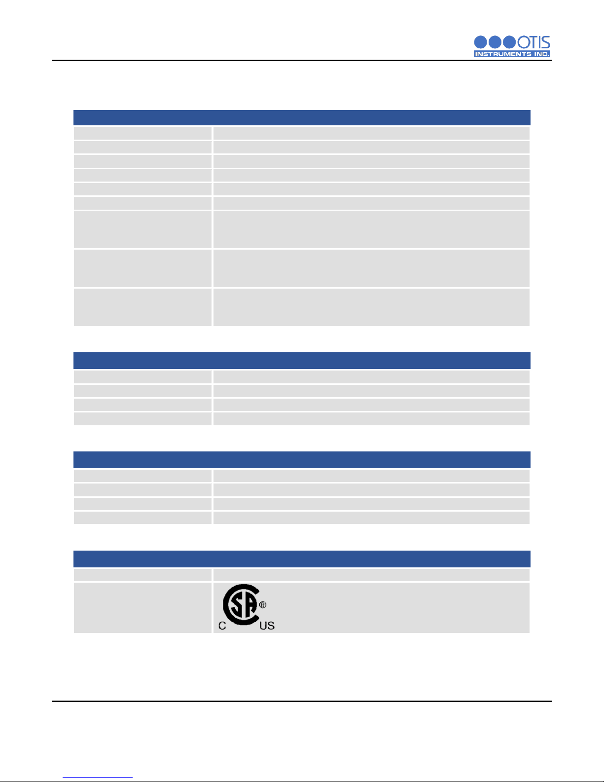
1.2PRODUCT SPECIFICATIONS
System Specifications
Operating Voltage
+12 to +35 VDC
Current Draw
250 mA Maximum
Operating Temperature Range
-40⁰C to +54⁰C
Humidity Range
0% to 98% Relative Humidity, Noncondensing
Measurement Range
Varies based on gas type
Response Time
Varies based on gas type
Protection
Power Electromagnetic Interference (EMI) Filter
4-20 mA Surge Suppression
RS-485 Modbus Surge Suppression
Display
Transflective (sunlight-readable)
102x64 LCD Screen
LED Back-Light
Interface
3 Push-Buttons (MENU, ADD, SUB)
3 Magnetic Switches for Non-Intrusive Operation
LOW and HIGH Alarm Indicator LEDs
Outputs
Wired (Analog)
4-20 mA (3-Wire)
Wired (Digital)
RS-485 Modbus RTU
WireFree (Optional)
GEN II 900 MHz or GEN II 2.4 GHz
Relays (Optional)
Two Dry Contact Relays with Replaceable 4 Amp Fuses
.
Mechanical Specifications
Enclosure Materials
Aluminum Device Enclosure
Sensor Housing Materials
303 Stainless Steel Sensor Housing
Product Dimensions
5.5” T x 6” W x 7” H (8” W x 17” H Maximum w/ Antenna Fitting and Antenna)
Product Weight
6 lbs.
Safety Approvals
Enclosure Ratings
Explosion/Flame-Proof
Hazardous Location Certification
Class I, Division 1, Groups C and D, T6
Ex d IIB T6
Zone 1, AEx d IIB T6
Tamb -40⁰C to +54⁰C
PRODUCT OVERVIEW
OI-6000-X-X-X-X-O OPS_GUIDE_REV 3.1 3
1.3SYSTEM DIAGRAMS
Refer to the following diagrams for identification of the external and internal system components that may be referred
to in this manual.
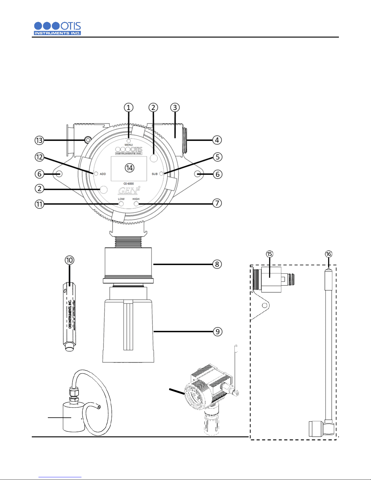
1.3.1 EXTERNAL SYSTEM DIAGRAM
1MENU Button
2Front Panel Thumbscrew
3Enclosure
4Explosion Proof Plug
5SUB Button
6Mounting Hole
7HIGH Alarm LED
8Sensor Housing Assembly
9Sensor Rain Guard
10Otis Magnetic Tool
11LOW Alarm LED
12ADD Button
13Enclosure Lid Locking Screw
14Display Screen
15Optional Antenna Fitting
(Replaces Item 4)
16Optional Antenna
17Enclosure Lid
18Calibration Kit (Sold Separately)
⑰
⑱

PRODUCT OVERVIEW
4 OI-6000-X-X-X-X-O OPS_GUIDE_REV 3.1
1.3.2 INTERNAL SYSTEM DIAGRAM
1RS-485 Modbus Terminal Block
2Fault Terminal Block
3Power Input/4-20mA Output Terminal Block
4Radio Module (If equipped)
5Sensor Housing Socket
6Antenna Fitting Connector (If equipped with a radio module)
7Relay 1 Terminal Block (If equipped with relays)
8Relay 2 Terminal Block (If equipped with relays)

PRODUCT OVERVIEW
OI-6000-X-X-X-X-O OPS_GUIDE_REV 3.1 5
1.3.3 ASSEMBLY DIAGRAM
1Enclosure Lid
2Internal System
3Antenna Fitting Plug (If equipped with a radio module)
4Enclosure Body
5Antenna Fitting (If equipped with a radio module) or #7 (If not equipped with a radio module)
6900 MHz or 2.4 GHz Antenna (If equipped with a radio module)
7Explosion Proof Plug (If not equipped with a radio module)
8Sensor Housing Base
9Sensor Element
10 Sensor Rain Guard
11 Sensor Housing Cap with Flame Arrestor
12 Analog Sensor Board
13 Sensor Housing Plug

INSTALLATION AND STARTUP
6 OI-6000-X-X-X-X-O OPS_GUIDE_REV 3.1
2INSTALLATION AND START-UP
2.1PRODUCT PLACEMENT
The installation instructions, and any other information supplied by Otis, provide only basic guidelines relating to the
properties of toxic gas and the effects of environmental conditions on the OI-6000 device. Sensor placement should
be determined in consultation with the site safety personnel, as well as those knowledgeable of: (1) the site/facility
where the equipment is being installed and (2) the potentially present gas types and their dispersion. Otis strongly
recommends that the end-user consults with the appropriate third party Health, Safety and Environmental (HSE) and
Industrial Hygiene (IH) professionals to determine the final quantity and placement of your gas detection devices.
The primary purpose of the OI-6000 is to provide an early warning of the accumulation of hazardous gas, in order to
minimize hazards to people and property. Proper placement of the device is paramount to achieving this goal.
The following general guidelines should be considered when determining the placement of the OI-6000:
Units with a radio installed should be placed greater than 6.5 Feet/2 Meters away from a monitor in order to
ensure reliable communications
The unit shall be placed such that the position of the sensor housing is pointing downward to the ground.
Avoid installing the unit in a location where airborne particles could cover or coat the sensor head.
The unit should be placed in an area that will produce the highest gas concentration. Enclosed corners and
stopping points of moving devices are two areas susceptible to a buildup of hazardous gas.
In order to provide an accurate representative sample of a room, care should be taken to avoid locating the
unit near a room entrance, fresh air intake vent, or vehicle/generator exhaust point.
The unit should be placed as close as physically possible to the source of the potential hazardous gas leak.
In consideration of possible ignition points, the unit should be placed between the potential leak source and
ignition point.
Consider placing the unit in a seldom used area, such as a warehouse, storage area, or other unfrequented
location.
Consider accessibility for regular calibration and other required maintenance.
When monitoring a ventilated gas cylinder storage area, the unit should be placed near the air return vent.
When monitoring an outdoor or open-air area, the unit should be placed near the air intake of the HVAC
system of the building.
When monitoring for the potential presence of multiple hazardous gas types, the unit should be calibrated for
the least cross-sensitive hazardous gas.
NOTICE
These guidelines are ONLY intended as a general directive for the placement of the OI-6000. This information
should NOT serve as a complete list when considering all potential parameters for the proper location of the unit.
It is STRONGLY advised that a third party Certified Industrial Hygienist, or other Certified Safety Professional,
conduct a site survey and annotate the location and quantity of detection devices that should be installed for
EVERY installation of EVERY site.
INSTALLATION AND STARTUP
OI-6000-X-X-X-X-O OPS_GUIDE_REV 3.1 7
2.2PRODUCT MOUNTING
It is recommended to mount the unit to a solid structure (such as a concrete wall, steel column, or angle iron) where
a minimum of vibration will be transmitted to the unit. Alternately, a pole may be used along with a strap or a U-bolt,
as long as it is rigid and of sufficient strength. Wooden structures are not recommended for mounting, as they trap
moisture (which could affect sensor performance) and their mounting rigidity degrades over time (screws/bolts
weaken and fall out or corrode).
Any style of bolt or screw may be used as long as it is steel and meets or exceeds the following:
Maximum ¼"-20 bolt or ؼ" screw (length varies with user need)
Flat washers for bolts/nuts/screws
Minimum Grade 5 (or better)
Corrosion protection for all hardware (paint, galvanize, zinc plating, etc.)
2.3WIRING CONFIGURATIONS
The OI-6000 has several basic wiring configurations, dependent upon the desired usage and functionality intended
by the end-user. All OI-6000 units require +12 to +35 Volts of wired DC power to operate. Data communication from
the device, through either the 4-20 output or the RS-485 Modbus connection, to an external location are optional.
Consult the subsequent sections of wiring instructions for pertinent information and guidelines pertaining to the
installation of your device.
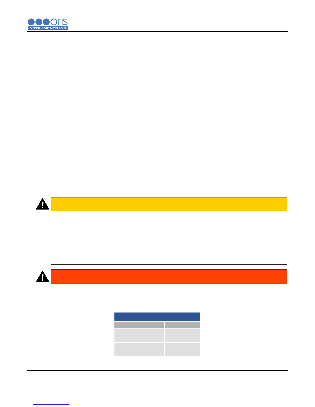
CAUTION
VERIFY that the power source is disabled before beginning the following wiring steps or performing any
maintenance inside the device enclosure.
The internal components can be static sensitive. Use caution when opening the enclosure and handling
internal components.
DO NOT use any metal objects or tools to remove the terminal board from the internal system.
VERIFY that the label and color combination of the control board terminal exactly matches the
corresponding label and color combination of the power terminal.
WARNING
When securing the lid onto the device, tighten the enclosure lid by hand ONLY. Overtightening of the lid by
use of hand-tools could result in damage to the O-ring, potentially compromising the moisture seal, resulting
in an unsafe environment.
OI-6000 Terminal Block Wire Gauges
Terminal Block
Wire Gauge
Power Terminal
Relay 1 & 2 Terminal
Min: 26 AWG
Max: 14 AWG
Modbus Terminal
Fault Terminal
Min: 26 AWG
Max: 16 AWG
AWG: American Wire Gauge

INSTALLATION AND STARTUP
8 OI-6000-X-X-X-X-O OPS_GUIDE_REV 3.1
2.3.1 OPENING THE ENCLOSURE
To prepare the OI-6000 for installation, you must first open the device, exposing the control board and its
components for wiring.
1. Remove the enclosure lid, unscrewing it from the device enclosure. Set aside.
2. Gripping the front panel thumbscrews, lift the internal system out of the enclosure and rest it against
the rim of the enclosure opening.
3. Locate the power cord grip on the top edge of the enclosure.
NOTICE
Disconnecting the sensor connector plug from the sensor housing will allow for the complete removal
of the internal system from the device enclosure. Disconnecting the internal system may provide ease
in accessing the control board terminals for wiring. If this step is performed, it is essential that all
connections are rejoined before returning the internal system back into the enclosure.
2.3.2 CONNECTING POWER
To provide power to the OI-6000, you will need to connect the power cable from the sensor terminal block
on an Otis monitor, or alternate user supplied power source, to the OI-6000 power terminal block located
on the back of the control board. Refer to the following instructions for how to wire your device:
On the GEN II Model OI-6000 Detector:
1. Feed the power wires through the power hub and into the enclosure.
2. Locate the power terminal block on the control board and complete the following:
a. Connect the power (WHITE) wire to the “+12 to +35 VDC” terminal.
b. Connect the ground (BLACK) wire to the “GND” terminal.
On the Otis Monitor:
1. Open the enclosure lid.
2. Using your thumb and forefinger, loosen the front panel thumbscrews that secure the internal system
into the enclosure.
3. Open the internal system, exposing the internal hardware.
4. Feed the power wires through a cord grip and into the enclosure.

INSTALLATION AND STARTUP
OI-6000-X-X-X-X-O OPS_GUIDE_REV 3.1 9
5. Locate the sensor terminal block on the control board and complete the following:
a. Connect the power (WHITE) wire to the “+12 to +35 VDC” terminal.
b. Connect the ground (BLACK) wire to the “GND” terminal.
OTIS MONITOR
SENSOR TERMINALS
OI-6000
POWER TERMINALS
+12 to +35 VDC
WHITE
+12 to +35 VDC
WHITE
GND
BLACK
GND
BLACK
4-20 mA
4-20 mA
NOTICE
Wiring power to the device is the ONLY requirement for the OI-6000 to operate. With the provision of
power, the unit will function normally, indicating the presence of toxic gas at the sensor and providing
the gas level reading on the display screen. To utilize the added functionality of the device, additional
wiring is necessary. If an Otis Monitor is not used, the OI-6000 can be powered from any +12 to +35
VDC power supply that is capable of supplying at least 250 mA.

INSTALLATION AND STARTUP
10 OI-6000-X-X-X-X-O OPS_GUIDE_REV 3.1
2.3.3 CONNECTING 4-20 MA OUTPUT
To utilize the 4-20 mA wired data output feature of the OI-6000, you will need to connect the signal cable
from your Otis Monitor sensor terminal block to the OI-6000 power terminal block located on the control
board. Refer to the following instructions for how to wire your device:
On the GEN II Model OI-6000 Detector:
1. Feed the signal wire through the power hub and into the enclosure.
NOTICE
The power and signal wires may be conjoined as a 3-wire cable, incorporating the power (WHITE),
ground (BLACK), and signal (GREEN) wires all into one jacketed cable.
2. Locate the power terminal block on the control board and complete the following:
a. Connect the signal (GREEN) wire to the “4-20 mA” terminal.
On the Otis Monitor:
1. Feed the signal wire through the power hub and into the enclosure.
2. Locate the sensor terminal block on the control board and complete the following:
a. Connect the signal (GREEN) wire to the “4-20 mA” terminal.

INSTALLATION AND STARTUP
OI-6000-X-X-X-X-O OPS_GUIDE_REV 3.1 11
OTIS MONITOR
SENSOR TERMINAL
OI-6000
POWER TERMINAL
+12 to +35 VDC
WHITE
+12 to +35 VDC
WHITE
GND
BLACK
GND
BLACK
4-20 mA
GREEN
4-20 mA
GREEN

INSTALLATION AND STARTUP
12 OI-6000-X-X-X-X-O OPS_GUIDE_REV 3.1
2.3.4 CONNECTING RS-485
The OI-6000 supports Modbus RTU over a RS-485 link. To integrate your device with RS-485 Modbus
data communications, you will need to connect the Modbus cable from your Otis Monitor RS-485 input
terminal block to the OI-6000 RS-485 output terminal block located on the control board of the unit. Refer
to the following instructions for how to wire your device:
On the GEN II Model OI-6000 Detector:
1. Feed the RS-485 cable through the power hub and into the enclosure.
2. Locate the RS-485 output terminal block on the control board and complete the following:
a. Connect the RS-485 B (BROWN) wire to the “B” terminal.
b. Connect the ground (WHITE) wire to the “GND” terminal.
c. Connect the RS-485 A (YELLOW) wire to the “A” terminal.
On the Otis Monitor:
1. Feed the RS-485 cable through the power hub and into the enclosure.
2. Locate the RS-485 input terminal block on the control board and complete the following:
a. Connect the RS-485 B (BROWN) wire to the “B” terminal.
b. Connect the ground (WHITE) wire to the “GND” terminal.
c. Connect the RS-485 A (YELLOW) wire to the “A” terminal.

INSTALLATION AND STARTUP
OI-6000-X-X-X-X-O OPS_GUIDE_REV 3.1 13
OTIS MONITOR
RS-485 TERMINAL
OI-6000
RS-485 TERMINAL
A
YELLOW
A
YELLOW
GND
WHITE
GND
WHITE
B
BROWN
B
BROWN
NOTICE
If an Otis Monitor is not used, the OI-6000 can be connected to a Programmable Logic Controller
(PLC) for RS-485 Modbus data communications. For integration and setup, refer to the Modbus
Register Map found in Appendix C of this manual.

INSTALLATION AND STARTUP
14 OI-6000-X-X-X-X-O OPS_GUIDE_REV 3.1
2.3.5 CONNECTING RELAYS/ALARMS
The OI-6000 relays are commonly used to power and control external alarming devices, such as alarm
lights (visual) and horns (audio). Refer to the following instructions for how to wire your device. If you do
not have relays in your OI-6000 skip to section 2.3.6 CONNECTING THE FAULT TERMINAL.
2.3.5.1 CONNECTING RELAY 1
On the OI-6000 Detector:
1. Locate the power terminal block on the control board and complete the following:
a. Connect a second power (BLUE) wire to the “+12 to +35 VDC” terminal.
2. Locate the Relay 1 terminal block on the radio/relay board and complete the following:
a. Connect the power (BLUE) wire from the “+12 to +35 VDC” terminal to the “COM” terminal.
NOTICE
Relays are protected by replaceable 4 Amp fuses.
The two protective fuses must only be replaced with OI-FUSE-4A-250.
Table of contents
Other OTIS Other manuals

Popular Other manuals by other brands

PureFlow AirDog
PureFlow AirDog AirDog II DF-100 installation manual

IRO
IRO LUNA X3 operating instructions

PCP
PCP Mendip Shower Tray installation instructions

Osaka
Osaka TERMOLOGGER USB-THR Installation and operation guide

Paradyne
Paradyne FrameSaver SLV 9626 installation guide

Haier
Haier CXW-219-D68VQ manual

Perfect Aire
Perfect Aire Damp2Dry 2PACD200 user manual

Motorola
Motorola RD5000 Integrator guide

EMG
EMG 81-TW-X Installation information

Havis
Havis KK-K9-F18-K Installation instructions manual

PPE
PPE High Idle/Valet Switch installation guide

unGer
unGer nLite HydroPower HP12 Series Installation & operating instruction


