Ouellet ELD09KCH15S User manual

Please read this owner’s manual carefully
before operating the unit and keep it for future reference.
DUCTLESS SINGLE ZONE
HEAT PUMP
INS529-201701-00
Owner’s Manual
15 SEER INVERTER
9 000 to 24 000 BTU/hr
Models:
Heating and Cooling
ELD09KCH15S
ELD12KCH15S
ELD18KCH15S
ELD24KCH15S
Cooling Only
ELD09KCO15S
ELD12KCO15S
ELD18KCO15S
ELD24KCO15S

2
TABLE OF CONTENTS
Operation notices .................................................................................................................................................................3
Explanation of symbols ........................................................................................................................................................3
Precautions................................................................................................................................................................................4
Working temperature range...............................................................................................................................................6
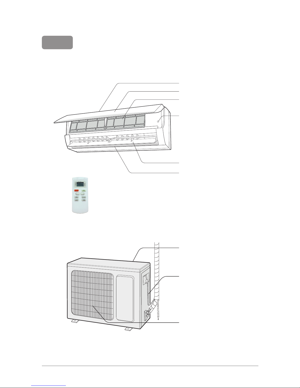
Parts name.................................................................................................................................................................................7
Indoor unit screen display...................................................................................................................................................8
Remote control .......................................................................................................................................................................9
Buttons on remote control..................................................................................................................................................9
Icon identication on remote control display..............................................................................................................9
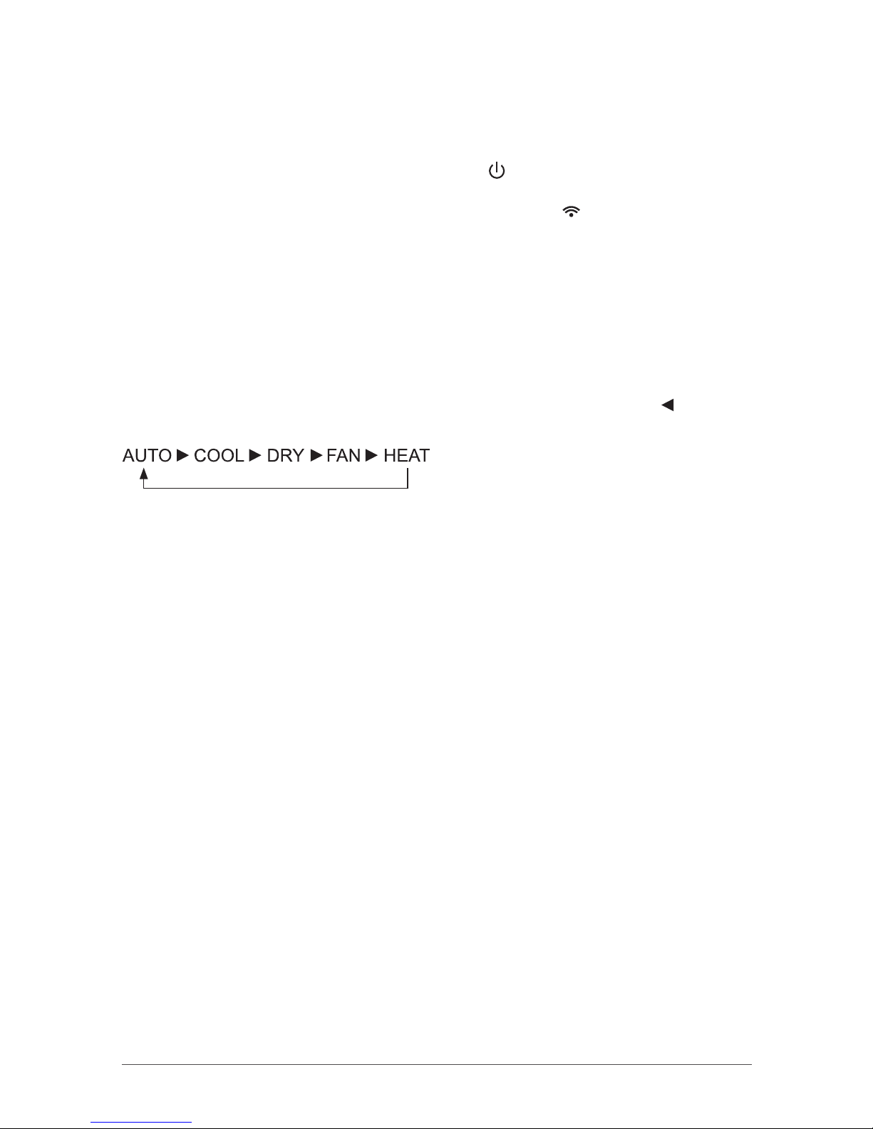
Operation of remote control............................................................................................................................................ 10
Special functions.................................................................................................................................................................. 12
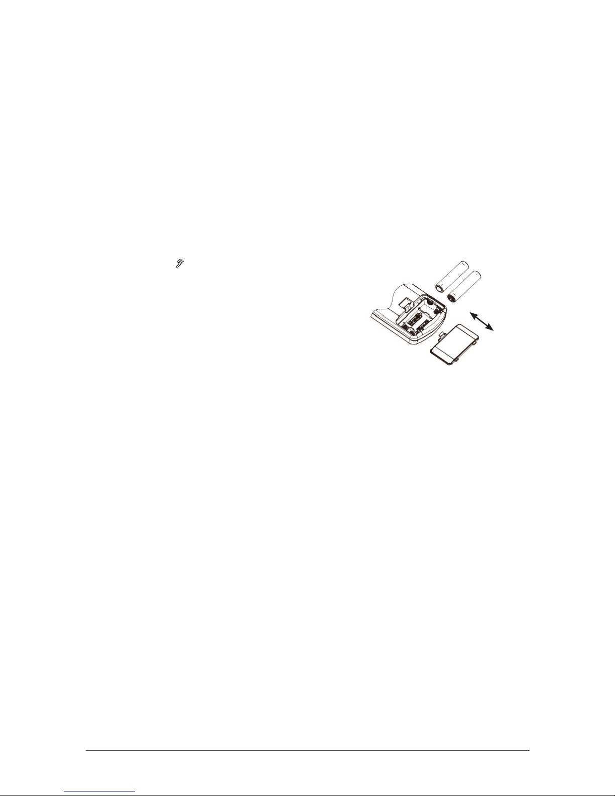
Replacement of batteries in remote control.............................................................................................................. 12
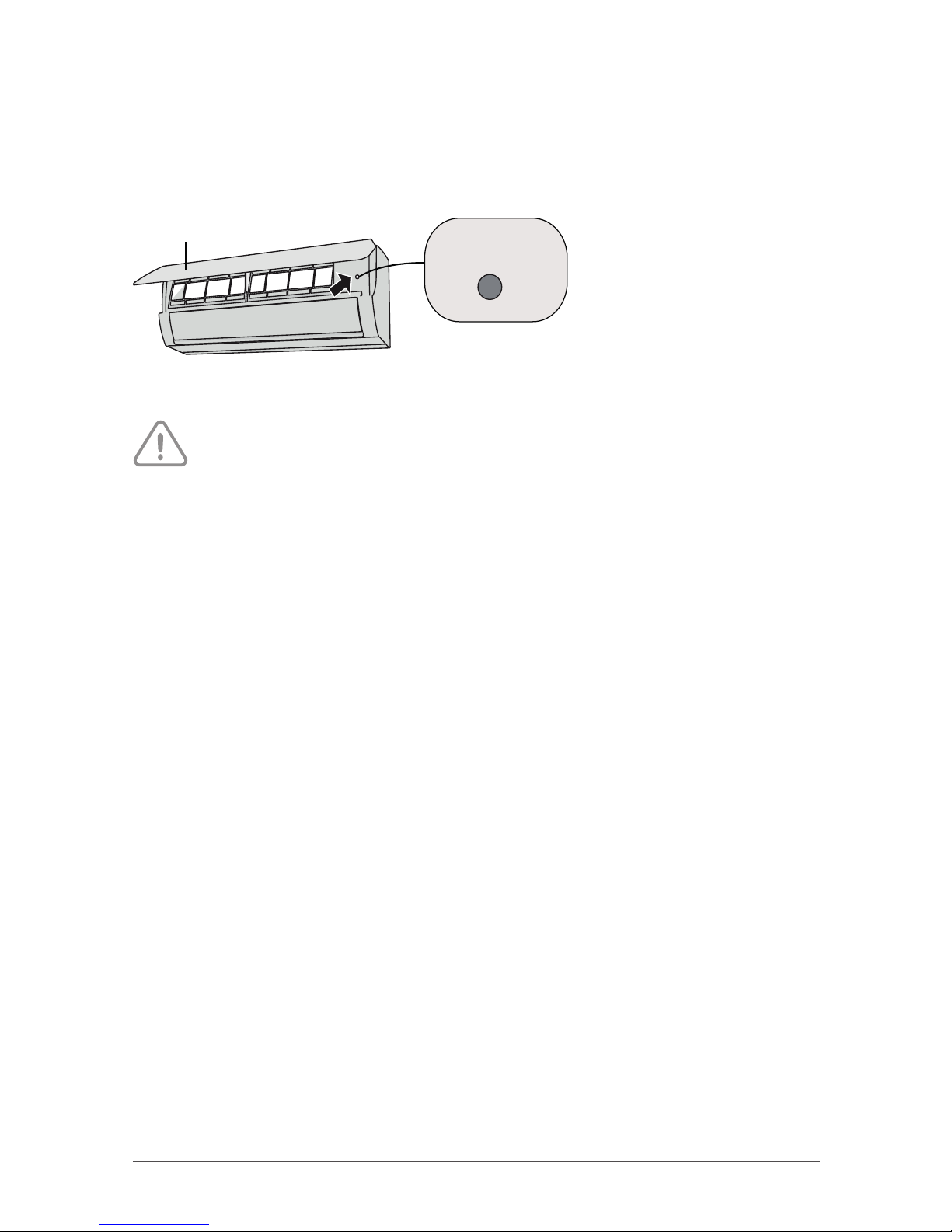
Emergency operation......................................................................................................................................................... 13
Maintenance.......................................................................................................................................................................... 14
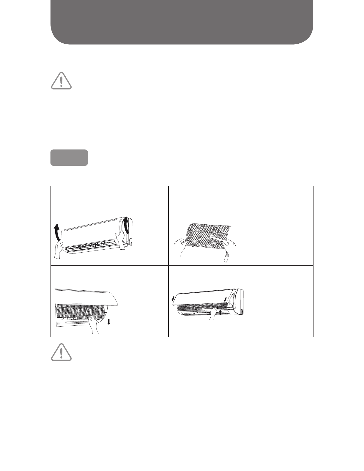
Cleaning and maintenance.............................................................................................................................................. 14
Malfunction............................................................................................................................................................................ 16
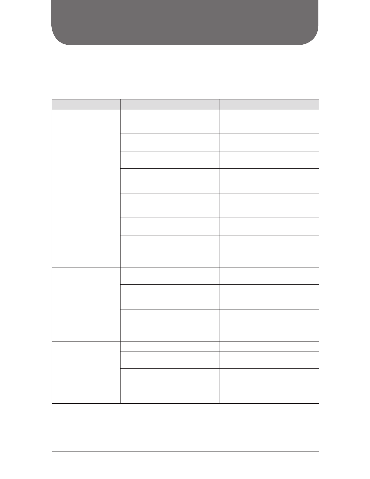
Malfunction analysis........................................................................................................................................................... 16
Error codes.............................................................................................................................................................................. 18
Preparation before installation............................................................................................................................... 19
Required installation clearance distances diagram................................................................................................. 19
Safety precautions for installing and relocating the unit...................................................................................... 20
Tools required for installation.......................................................................................................................................... 21
Selection of installation location.................................................................................................................................... 21
Requirements for electrical connection ...................................................................................................................... 22
Installation.............................................................................................................................................................................. 23
Installation of indoor unit ................................................................................................................................................ 23
Installation of outdoor unit.............................................................................................................................................. 27
Vacuum pumping................................................................................................................................................................ 30
Leakage detection............................................................................................................................................................... 30
Checking after installation ............................................................................................................................................... 31
Operation test....................................................................................................................................................................... 32
Other considerations....................................................................................................................................................... 33
Conguration of connection pipes ............................................................................................................................... 33
Pipe expanding method.................................................................................................................................................... 34
This appliance is not intended for use by people (including children) with
reduced physical, sensory or mental capabilities, or lack of experience and
knowledge, unless they are under the supervision or instruction
concerning use of the appliance by a person responsible for their safety.
Children should be supervised to ensure that they do not play with the appliance.

3
OPERATION NOTICES
EXPLANATION OF SYMBOLS
Indicates a hazardous situation that, if not avoided,
will result in serious injury or death.
Indicates a hazardous situation that, if not avoided,
could result in serious injury or death.
Indicates a hazardous situation that, if not avoided,
may result in minor or moderate injury.
Indicates important but not hazard-related information,
used to indicate risk of property damage.
Indicates a hazard and it is assigned to the signal words
DANGER, WARNING or CAUTION.
CAUTION
WARNING
NOTICE
DANGER

4
PRECAUTIONS
Operation and Maintenance
• This appliance can be used by people (including children of 8 years old and above) with reduced
physical, sensory or mental capabilities, or lack of experience and knowledge, as long as they are
under the supervision or instruction concerning use of the appliance by a person responsible for
their safety.
• Children shall not play with the appliance.
• Cleaning and user maintenance shall not be made by children.
• Do not connect to multi-purpose socket. Otherwise, it may cause re hazard.
• Disconnect power supply when cleaning. Otherwise, it may cause electric shock.
• If the power supply wire is damaged, it must be replaced by a qualied person in order to avoid
a hazard.
• Do not wash with water to avoid electric shock.
• Do not spray water on indoor unit. It may cause electric shock or malfunction.
• After removing the lter, do not touch ns to avoid injury.
• Do not use re or hair dryer to dry the lter to avoid deformation or re hazard.
• Maintenance must be performed by qualied person. Otherwise, it may cause personal injury
or damage.
• Do not repair the appliance by yourself. It may cause electric shock or damage. Please contact
a qualied person when you need to repair it.
• Do not extend ngers or objects into air inlet or air outlet. It may cause personal injury or damage.
• Do not block air outlet or air inlet. It may cause malfunction.
• Do not spill water on the remote control, otherwise it could damage the remote.
• When below phenomenon occurs, please turn o the appliance and disconnect power immediately,
and then contact a qualied person for service:
- There’s abnormal sound during operation.
- Circuit break trips o frequently.
- The appliance gives o burning smell.
- Indoor unit is leaking.
• If the appliance operates in an inappropriate environment or under abnormal conditions, it may cause
malfunction, electric shock or re hazard.
• When turning on or turning o the unit by emergency operation button, please press this button
with an insulated object other than metal.
• Do not step on top panel of outdoor unit, or put on heavy objects. It may cause damage or personal
injury.
WARNING

5
PRECAUTIONS
Wiring
• Installation must be performed by a qualied person. Otherwise, it may cause personal injury or
damage.
• Must follow the electric safety regulations when installing the unit.
• According to the local safety regulations, use qualied power supply circuit and circuit breaker.
• Install a circuit breaker of adequate capacity only used for the system; otherwise, it may cause
malfunction.
• An all-pole disconnection switch having a contact separation of at least 3 mm in all poles should be
connected in xed wiring.
• The appliance should be properly grounded. Incorrect grounding may cause electric shock.
• Make sure the power supply matches with the requirement of the appliance. Unstable power supply
or incorrect wiring may cause malfunction of the unit, electric shock or re hazard.
• Properly connect the live wire, neutral wire and grounding wire.
• Be sure to cut o the power supply before proceeding any work related to electricity and safety.
• Do not turn the power on before nishing installation.
• If the supply cord is damaged, it must be replaced by a qualied person in order to avoid problems.
• The temperature of refrigerant circuit will be high, please keep the interconnection cable away from
the copper tube.
• The appliance shall be installed in accordance with national wiring regulations.
• Installation must be performed in accordance with the requirement of NEC and CEC by a qualied
person only.
• The heat pump is a rst class electric appliance. It must be properly grounded with specialized
grounding device by a qualied person. Please make sure it is always properly grounded, otherwise
it may cause electric shock.
• The yellow-green wire in the appliance is the grounding wire, which can’t be used for other purposes.
• The grounding resistance should comply with national electric safety regulations.
• All wires of indoor unit and outdoor unit should be connected by a qualied person.
• If the length of power connection wire is insucient, please contact the dealer for a new one. Do not
extend the wire yourself.
WARNING

6
PRECAUTIONS
Location
• If you need to relocate the appliance to another place, only a qualied person can perform
the work. Otherwise, it may cause personal injury or damage.
• Select a location which is out of reach for children and far away from animals or plants. If it is
unavoidable, please add a fence around the outdoor unit for safety purpose.
• Instructions for installation and use of this product are provided by the manufacturer.
WORKING TEMPERATURE RANGE
Indoor side DB/WB °C (°F) Outdoor side DB/WB °C (°F)
Max. cooling 27/19 (80/67) 46/24 (115/75)
Max. heating 27/- (80/-) 24/18 (75/65)
The operating ambient temperature range is:
Cooling mode: 18 to 46 °C (64 to 115 °F)
Heating mode: -7 to 24 °C (19 to 75 °F)
WARNING
NOTICE

7
PARTS NAME
Actual product may be dierent from below graphics, please refer to actual product
for reference purposes.
Indoor unit
Remote Control
Outdoor unit
NOTICE
Panel
Filter
Air outlet
Air inlet
Horizontal louvre
AUX button
Air inlet
Connection wire
Air outlet

8
INDOOR UNIT SCREEN DISPLAY
Actual product may be dierent from below graphics, please refer to actual product
for reference purposes.
NOTICE
Cooling
indicator
Heating
indicator
Temperature
indicator
Drying
indicator
Power
indicator
Receiver
window
Display

9
REMOTE CONTROL
BUTTONS ON REMOTE CONTROL
No. Button Function
1 ON/OFF Turn on or turn o the unit
2 MODE Set operation mode
3 -/+ Set temperature and time
4FAN Set fan speed
5 SWING Set fan oscillating angle
6SLEEP Lowering or raising the temperature gradual-
ly during the night
7 TIMER Set starting and ending time
1
3
4
2
6
3
7
5
ICON IDENTIFICATION
ON REMOTE CONTROL DISPLAY
Swing operation
Sending signal
Timer OFF
Set timeSet temperature
Timer ON
Sleep operation
Lock
Set speed
Auto operation
Cool operation
Dry operation
Fan operation
Heat operation
T-ON T-OFF
SWING
AUTO
SLEEP
COOL
LOCK
DRY
SPEED
FAN
HEAT

10
OPERATION OF REMOTE CONTROL
NOTES:
• This is a general remote control that could be used for multifunction appliances. If you push a button
which is not featured on the model, the unit will continue to work as is.
• After powering it, the device will beep. Working indicator " " is activated (in red). After that, you can
operate the unit with the remote control.
• In ON mode, when you push a button on the remote control, the icon " " blinks one time and device
beeps to conrm that the signal has been sent to the appliance.
• In OFF mode, set temperature will be displayed on the remote control. In ON mode, display will show
icons of chosen functions.
1. ON/OFF button
Pushing this button allows to turn on or o the device.
2. MODE button
Push this button in order to select operating mode of your choice (as shown below). Icon " " will be
displayed on the remote control beside selected mode. :
(Only for models with heating function.)
AUTO mode:
When you select automatic mode, the device automatically selects the appropriate function to main-
tain temperature between 20 °C and 25 °C. In this mode, temperature can’t be changed or displayed on
remote control.
COOL mode:
When you select COOL mode, the appliance is cooling the room. Press " + " or " - " to set temperature.
DRY mode:
When you select DRY mode, the appliance is in dehumidifying mode and works at its lowest speed. In this
mode, the fan speed can’t be changed.
FAN mode:
When you select FAN mode, only the fan is operating. There is no heating, nor cooling in this mode.
HEAT mode:
When you select HEAT mode, device is working on heating mode. Press the " + " or " - " button to adjust
temperature.
NOTE :
Cooling only unit cannot receive heating mode signal.
3. +/- button
Push " + " or " - " button to decrease or increase temperature by 1 degree at a time.
Maintain " + " or " - " button pushed for 2 seconds in order to change rapidly temperature. Once settings
done, release button and temperature will be modied accordingly (temperature can’t be settled in AUTO
mode).
While adjusting TIMER ON or TIMER OFF, push " + " or " - " button to set the time. (Please see section TIMER
button for more details.)

11
4. FAN button
Push this button to select the fan speed along this sequence:
Automatic (AUTO), speed 1 ( ), speed 2 ( ), speed 3 ( ), speed 4 ( ).
NOTES:
• On AUTO speed, the device will choose ideal speed according to room temperature and set
temperature.
• In DRY mode (dehumidication), fan always goes at low speed.
5. SWING button
Press this button to turn on up and down air swing.
6. SLEEP button
SLEEP function is available in COOL (cooling), DRY (dehumidifer) and HEAT (heating) modes only. This
function permits to gradually increase room temperature in COOL mode and to lower it in HEAT mode.
You will then save energy without aecting your sleep. This function is settled over an 8-hour
period. After this period of time, the device will work on previous established parameters, as it was set
before SLEEP function was activated.
Press this button to activate SLEEP function and the icon " " will appear on remote control, beside
SLEEP function. Press again this button to cancel SLEEP function and the icon disappears.
7. TIMER button
This timer function allows you to program the unit while determining when it starts and when it ends.
When unit is o, press this button to set TIMER ON. T-ON and H icon will be blinking on the screen. Within
5 seconds, push " + " or " - " button to adjust the time for TIMER ON. Pressing " + " or " - " button once will
increase or decrease the time by 0.5 hour. Hold " + " or " - " button for 2 seconds and time will change
quickly. Release the button after your required set time is reached. Then press TIMER button to conrm it.
T-ON and H icon will stop blinking.
When unit is on, press this button to set TIMER OFF. T-OFF and icon "H" will be blinking on the screen. Wit-
hin 5 seconds, push " + " or " - " button to adjust the time for TIMER OFF. Pressing " + " or " - " button once
will increase or decrease the time by 0.5 hour. Hold " + " or " - " button for 2 seconds and time will change
quickly. Release the button after your required set time is reached. Then press TIMER button to conrm it.
T-OFF and H icon will stop blinking.
To cancel TIMER function, press TIMER button once to review the remaining time. Within 5 seconds, press
TIMER button again to cancel this function.
NOTE:
• Range of time setting is: 0.5 to 24 hours

12
SPECIAL FUNCTIONS
Child lock function
This function eliminates unwanted temperature adjustments and the use of dierent modes on the
device. Before activating it, make sure to have set the temperature as you like.
Press simultaneously " + " and " - " buttons to activate or deactivate the child lock function. When that
function is activated, LOCK indicator on the remote control is on.
Temperature display in °C or °F
When device is turned o (OFF), press simultaneously on " - " and MODE buttons to switch from °C or °F.
REPLACING BATTERIES IN REMOTE CONTROL
1. Lightly press the " " and slide in the direction the arrow
is pointing to remove the back cover of the remote control
(as illustrated).
2. Remove the old batteries (as illustrated).
3. Insert two new " AAA " (1.5 V) dry batteries and make sure
the position of + and – is correct (as illustrated).
4. Put back the cover (as illustrated).
NOTES:
• During operation, point the remote control at the receiving window on the indoor unit.
• The distance between the remote control and receiving window should not be more than
26.25 ft. (8 m) and there should be no obstacle between them.
• The remote control should be placed 3.3 ft. (1 m) away from TV or Audio sets.
• The signal can be easily interfered in a room where there is a uorescent lamp or wireless phone;
the remote control should be near the indoor unit when operating.
• If the remote control does not operate normally, please take out the batteries and reinsert them
after 30 seconds. If it is still not working, replace the batteries.
• When replacing batteries, use only new and identical ones (same brand).
• When you do not use the remote control for a long time, take out the batteries.
Reinstall
Remove
Cover of battery box
Battery

13
EMERGENCY OPERATION
If the remote control is lost or damaged, please use AUX button to turn on or turn o the appliance.
As illustrated, open the panel, press the AUX button to turn on or turn o the device.
When it is turned on, it will operate under AUTO mode.
Use insulated object other than metal to press the AUX button.
WARNING
panel
AUX button

14
MAINTENANCE
CLEANING AND MAINTENANCE
• Turn o the unit and disconnect the power before cleaning to avoid electric shock.
• Do not wash the unit with water to avoid electric shock.
• Do not use volatile liquid to clean the unit.
Cleaning the surface of indoor unit
When the surface of indoor unit is dirty, it is recommended to use a softdry cloth or lightly moistened
with water to wipe it.
Do not remove the panel when cleaning it.
Clean lter
1. Open panel
Open the panel into a certain angle as illus-
trated (less than 60°, do not force the panel).
3. Clean lter
Use a vacuum or water to clean the lter.
When the lter is very dirty, use water (below 45 °C) to
clean it, and then put it in a shady and cool place to dry.
2. Remove lter
Remove the lter as illustrated.
4. Install lter
Install the lter and then close the panel cover tightly.
• The lter should be cleaned every three months. If the unit operates in a highly dusty environment,
cleaning frequency should be increased.
• After removing the lter, do not touch ns to avoid injury or damage the unit.
• Do not use re or hair dryer to dry the lter to avoid deformation or re hazard.
WARNING
WARNING
NOTICE

15
Checking before usage
1. Check that air inlets and air outlets are not blocked.
2. Check if circuit breaker and connection are in good condition.
3. Check that lters are clean.
4. Check that drainage pipe is not damaged or blocked.
Checking after usage
1. Disconnect power supply.
2. Clean lters and indoor unit panel.
3. Check whether mounting bracket for outdoor unit is damaged or corroded.
If so, please contact the dealer.
Notice for recovery
1. Many packing materials are recyclable. Please dispose of them in appropriate recycling bin.
2. If you want to get rid of the device, please contact a local recycling center for the correct
disposal method.

16
MALFUNCTION
MALFUNCTION ANALYSIS
Please check below items before asking for servicing. If the malfunction still cannot be eliminated, please
contact a qualied person.
Phenomenon Items to check Solution
Indoor unit cannot
receive remote
control signal or
remote control does
not work.
Is there severe interferences (such as
static electricity, unstable voltage)?
Cut the power supply o and put the
power back after about 3 minutes,
and then turn on the unit again.
Is the remote control within the
signal receiving distance?
Signal receiving distance is
26.25 ft. (8 m).
Is there any obstacle between the
unit and the remote control? Remove obstacles.
Is the remote control pointing at the
receiving window of the indoor unit?
Select proper angle and point
the remote control at the receiving
window on indoor unit.
Is the remote control display fuzzy
or there is no display at all ?
Check the batteries. If the
battery charge level is too low,
please replace them.
No display when operating
the remote control?
Check if remote control is damaged.
If so, replace it.
Are there uorescent lamps in the
room?
Bring the remote control
close to the indoor unit.
Turn o the uorescent lamps
and then try it again.
No air ow
from indoor unit.
Are air inlet or air outlet of indoor
unit blocked? Eliminate obstacles.
Under heating mode, has indoor
temperature reached set
temperature?
After reaching set temperature,
indoor unit will stop blowing out air.
Has the heating mode been
just turned on?
In heating mode, in order to prevent
blowing out cold air, indoor unit will
start a few minutes after the unit has
been turned on, which is normal.
Appliance cannot
operate.
Is there a power failure? Wait until power resumes.
Circuit break trips o? Ask a qualied person to replace
circuit break or replace wiring.
Has the unit been turned on imme-
diately after being turned o?
Wait for 3 minutes, and then turn on
the unit again.
Are the function setting on the
remote control correct? Reset the functions

17
Phenomenon Items to check Solution
Mist is emitted from
indoor unit air outlet.
Are indoor temperature and
humidity level high?
This is because indoor air is
cooled rapidly. After a while,
indoor temperature and humidity
level will decrease and mist will
disappear.
Set temperature
cannot be adjusted.
Is the unit operating under AUTO
mode?
Temperature cannot be adjusted
under AUTO mode.
Please switch the operationmode
if you need to adjust temperature.
Does your required temperature
exceed the set temperature range?
Set temperature range:
16 °C to 30 °C (61 °F to 86 °F).
Air cooling (heating)
is not ecient.
Is voltage too low? Wait until the voltage comes back
to normal.
Is lter dirty? Clean the lter.
Is the set temperature in proper
range?
Adjust temperature within proper
range.
Are doors and windows open? Close doors and windows.
Odours are emitted.
Is there an odour source in the room,
such as furniture or cigarette. Eliminate the odour source.
Is the lter dirty? Clean the lter.
Appliance suddenly
operates abnormally.
There may be interferences, such as
thunder, wireless devices, etc.
Cut the power supply o and put
the power back. Then turn on the
unit again.
Outdoor unit emits
vapor. Is the unit in heating mode?
During defrosting under heating
mode, it may produce vapor,
which is normal.
Water owing noise. Has the air conditioner just
been turned on and o?
The noise is the sound of refrigerant
owing inside the unit, which
is normal.

18
ERROR CODES
When appliance status is abnormal, temperature indicator on indoor unit will blink and display corres-
ponding error code. Please refer to list below for identication of error code.
Error
code What to do?
C5 Please contact a qualied person for service.
E2 Verify if lter needs to be cleaned. Make sure nothing is blocking air inlet or outlet.
Restart device. If not, please contact a qualied person for service.
E5 It can be eliminated after restarting the unit. If not, please a qualied person for service.
E6 It can be eliminated after restarting the unit. If not, please contact a qualied person
for service.
E8 It can be eliminated after restarting the unit. If not, please contact a qualied person
for service.
F0 It can be eliminated by disconnecting power at the main panel. Wait 10 minutes before
energizing. If the error code remains, please contact a qualied person for service.
F1 Please contact a qualied person for service.
F2 Please contact a qualied person for service.
H1 This code indicates that device is in defrosting mode. When defrosting cycle is nished,
code will disappear.
H6 It can be eliminated after restarting the unit. If not, please contact a qualied person
for service.
U8 It can be eliminated after restarting the unit. If not, please contact a qualied person
for service.
Note: If there are other error codes, please contact a qualied person for service.
WARNING
When below phenomenon occurs, please turn o the unit and disconnect power immediately,
then contact a qualied person for service:
• There is an unusual sound during operation.
• Circuit break trips o frequently.
• Device generates a burning smell.
• Indoor unit is leaking.
• Power cord is overheating or damaged.
CAUTION
• Do not repair or ret the appliance by yourself.
• If the appliance operates under abnormal conditions, it may damage the unit, cause electric shock
or re hazard.

19
PREPARATION BEFORE INSTALLATION
REQUIRED INSTALLATION CLEARANCE DISTANCES DIAGRAM
At least 15 cm
Space to the ceiling
Space to the wall
Space to the wall
At least 15 cm
At least 15 cm
At least 250 cm
Space to the oor
At least 300 cm
Space to the obstruction
Space to the
obstruction
Drainage pipe
Space to the obstruction
At least 50 cm
At least 30 cm
At least 200 cm
At least 50 cm
At least 30 cm
Space to the wall

20
SAFETY PRECAUTIONS FOR INSTALLING AND RELOCATING THE UNIT
To ensure safety, please be mindful of the following precautions:
WARNING
• When installing or relocating the unit, be sure to keep the refrigerant circuit free from air or
substances other than the specied refrigerant.
Any presence of air or other foreign substance in the refrigerant circuit will cause system pressure rise
or compressor rupture, resulting in injury.
• When installing or moving this unit, do not charge the refrigerant which is not comply with that
on the nameplate or unqualied refrigerant.
Otherwise, it may cause abnormal operation, wrong action, mechanical malfunction or even series
safety accident.
• When refrigerant needs to be recovered during relocating or repairing the unit, be sure that the
unit is running in cooling mode.Then, fully close the valve at high pressure side (liquid valve).
About 30-40 seconds later, fully close the valve at low pressure side (gas valve), immediately
stop the unit and disconnect power. Please note that the time for refrigerant recovery should not
exceed 1 minute.
If refrigerant recovery takes too much time, air may be sucked in and cause pressure rise or compressor
rupture, resulting in injury.
• During refrigerant recovery, make sure that liquid valve and gas valve are fully closed and power
is disconnected before detaching the connection pipe.
If compressor starts running when stop valve is open and connection pipe is not yet connected, air will
be sucked in and cause pressure rise or compressor rupture, resulting in injury.
• When installing the unit, make sure that connection pipe is securely connected before the com-
pressor starts running.
If compressor starts running when stop valve is open and connection pipe is not yet connected, air will
be sucked in and cause pressure rise or compressor rupture, resulting in injury.
• Prohibit installing the unit at the place where there may be leaked corrosive gas or ammable
gas.
If there leaked gas around the unit, it may cause explosion and other accidents.
• Do not use extension cords for electrical connections. If the electric wire is not long enough,
please contact a local service center authorized and ask for a proper electric wire.
Poor connections may lead to electric shock or re.
• Use the specied types of wires for electrical connections between the indoor and outdoor units.
Firmly clamp the wires so that their terminals receive no external stresses.
Electric wires with insucient capacity, wrong wire connections and insecure wire terminals may cause
electric shock or re.
This manual suits for next models
7
Table of contents
Other Ouellet Air Conditioner manuals

Ouellet
Ouellet CLC18KCH16S User manual

Ouellet
Ouellet SMD09KCHVS-I User manual

Ouellet
Ouellet FLC18KCH16S User manual

Ouellet
Ouellet OCD09KCH23S User manual

Ouellet
Ouellet UHD09KCH38S User manual

Ouellet
Ouellet MPD18KCH22S-O User manual

Ouellet
Ouellet PUD09KCH23S User manual

Ouellet
Ouellet CCD12KCHVS-I User manual

Ouellet
Ouellet CMD09KCHVS-I User manual

Ouellet
Ouellet FCD12KCHVS-I User manual