OutBack Power SmartRE 3000 User manual

Installation Manual

About OutBack Power Systems
OutBack Power Systems is a leader in advanced energy conversion technology. Our products include
true sine wave inverter/chargers, maximum power point charge controllers, system communication
components, as well as breaker panels, breakers, accessories, and assembled systems.
Contact Information
Telephone: +1.360.435.6030 (North America)
+1.360.618.4363 (Technical Support)
+1.360.435.6019 (Fax)
+34.93.654.9568 (Barcelona, Spain)
Address: North America
19009 62nd Avenue NE
Arlington, WA USA
European Office:
C/ Castelló, 17
08830 - Sant Boi de Llobregat
BARCELONA, España
Web Site: www.outbackpower.com
Disclaimer
UNLESS SPECIFICALLY AGREED TO IN WRITING, OUTBACK POWER SYSTEMS:
(a) MAKES NO WARRANTY AS TO THE ACCURACY, SUFFICIENCY OR SUITABILITY OF ANY TECHNICAL
OR OTHER INFORMATION PROVIDED IN ITS MANUALS OR OTHER DOCUMENTATION.
(b) ASSUMES NO RESPONSIBILITY OR LIABILITY FOR LOSS OR DAMAGE, WHETHER DIRECT, INDIRECT,
CONSEQUENTIAL OR INCIDENTAL, WHICH MIGHT ARISE OUT OF THE USE OF SUCH INFORMATION. THE
USE OF ANY SUCH INFORMATION WILL BE ENTIRELY AT THE USER’S RISK.
Warranty Summary
OutBack Power Systems Inc. warrants that the products it manufactures will be free from defects in
materials and workmanship for a period of five (5) years subject to the conditions set forth in the
warranty detail found inside the back cover of this manual.
OutBack Power Systems cannot be responsible for system failure, damages, or injury resulting from
improper installation of their products.
Notice of Copyright
SmartRE™Installation Manual ©April 2009 by OutBack Power Systems. All Rights Reserved.
Trademarks
SmartRE is a registered trademark of OutBack Power Systems. OutBack Power is a registered
trademark of OutBack Power Systems.
Date and Revision
April 2009, Revision A
Part Number
900-0033-01-00 Rev A

900-0033-01-00 Rev A 1
Important Safety Instructions
READ AND SAVE THESE INSTRUCTIONS!
This manual contains important safety instructions for the SmartRE. Read all instructions and
cautionary markings on the SmartRE and on any accessories or additional equipment included in the
installation. Failure to adhere to these instructions could result in severe shock or possible
electrocution. Exercise extreme caution at all times to prevent accidents.
Symbols Used
Symbol Description
Ground
AC Current
DC Current
∅Single-Phase
Sine Wave
WARNING: Hazard to Human Life
This type of notation indicates that the hazard could be harmful to human life.
CAUTION: Hazard to Equipment
This type of notation indicates that the hazard may cause damage to
the equipment.
IMPORTANT:
This type of notation indicates that the information provided is important to
the installation, operation and/or maintenance of the equipment. Failure to
follow the recommendations in such a notation could result in voiding the
equipment warranty.
Audience
These instructions are for use by qualified personnel who meet all local and governmental code
requirements for licensing and training for the installation of electrical power systems with AC and DC
voltage up to 240 Vac and 150 Vdc.

Important Safety Instructions
2900-0033-01-00 Rev A
Definitions
Table 1 Terms and Acronyms used in this Installation Manual
Acronym Definition
AC Alternating Current
ANSI American National Standards Institute
DC Direct Current
FCC Federal Communications Commission (North America)
GND Ground
IEEE Institute of Electrical and Electronics Engineers
N AC Neutral
NEC National Electric Code (North America)
NFPA National Fire Protection Association
OSHA Occupational Safety and Health Association
PV Photovoltaic
RE Renewable Energy
UL Underwriters Laboratory
General Safety
WARNING: Limitations on Use
This equipment is NOT intended for use with life support equipment or other
medical equipment or devices.
CAUTION: Equipment Damage
Only use components or accessories recommended or sold by OutBack Power
Systems or its authorized agents.
IMPORTANT:
Do not attempt to install this equipment if it appears to be damaged in any
way. See the Troubleshooting Section for instructions on how to return the
equipment if you know, or suspect, it is damaged.
Important Safety Instructions
900-0033-01-00 Rev A 3
Personal Safety
WARNING: Personal Injury
¾This equipment weighs over 100 lbs (45 kg). Use safe lifting techniques
when lifting this equipment as prescribed by the Occupational Safety and
Health Association (OSHA) or other local codes.
¾Use standard safety equipment such as safety glasses, ear protection, steel-
toed safety boots, safety hard hats, etc. as prescribed by the Occupational
Safety and Health Association (or other local codes) when working on this
equipment.
¾Use standard safety practices when working with electrical equipment
(e.g., remove all jewelry, use insulated tools, wear cotton clothing, etc.)
¾Never work alone when installing or servicing this equipment. Have
someone nearby that can come to your aid if necessary.
SmartRE System Safety
WARNING: Lethal Voltage
¾Review the system configuration to identify all possible sources of energy.
Ensure ALL sources of power are disconnected before performing any
installation or maintenance on this equipment. Confirm that the terminals
are de-energized using a validated voltmeter (rated for a minimum
1000 Vac and 1000 Vdc) to verify the de-energized condition.
¾Do not perform any servicing other than that specified in the installation
instructions unless qualified to do so or as instructed to do so by OutBack
Power Systems Technical Support personnel.
WARNING: Burn Hazard
Internal parts can become hot during operation. Do not remove the cover
during operation or touch any internal parts. Be sure to allow them sufficient
time to cool down before attempting to perform any maintenance.
WARNING: Fire Hazard
¾In residential installations: check for multi-wire branch circuit wiring at the
location for the installation. A possible fire hazard can exist if 120 Vac only
sources (such as inverters and generators) are wired incorrectly into
120/240 Vac panels containing multi-wire branch circuits. Consult the local
electric code for assistance.
¾Do not place combustible or flammable materials within 12 feet (3.7 m) of
the equipment.
¾Use only the recommended cable sizes (or greater) for AC and DC
conductors in compliance with local codes. Ensure all conductors and
connections are in good condition. Do not operate the unit with damaged
or substandard cabling.
Important Safety Instructions
4900-0033-01-00 Rev A
CAUTION: Equipment Damage
¾When connecting cables from the inverter to the battery terminals, ensure
the proper polarity is observed. Connecting the cables incorrectly can
damage or destroy the equipment.
¾Thoroughly inspect the equipment prior to energizing. Verify that no tools
or equipment have been inadvertently left behind.
¾Ensure clearance requirements are strictly enforced and that all vents are
clear of obstructions that can prevent proper air flow around or through
the unit.
¾Sensitive electronics inside the equipment can be destroyed by static
electricity. Be sure to discharge any static electricity built up before
touching the equipment and wear appropriate protective gear.
PV Safety
WARNING: Shock Hazard
Photovoltaic (PV) arrays can be energized with minimal ambient light available.
Therefore to ensure a safe disconnect from the system, be sure to install a PV
disconnect, breaker, or accessible fuse box (depending on local code
requirements).
CAUTION: Equipment Damage
PV Arrays must be wired with correct polarity (positive-to-positive, negative-to-
negative). Connecting the cables incorrectly can damage or destroy the
equipment.
Battery Safety
WARNING: Electrocution Hazard
¾Use the battery types recommended by OutBack Power Systems. Follow
the battery manufacturer’s recommendations for installation and
maintenance.
¾Ensure clearance requirements are strictly enforced around batteries.
¾Ensure the area around the batteries is well ventilated and clean of debris.
¾Always use insulated tools. Avoid dropping tools onto batteries or other
electrical parts.
¾Keep plenty of fresh water and soap nearby in case battery acid contacts
skin, clothing, or eyes.
¾If you need to remove a battery, always remove the ground terminal from
the battery first. Make sure all accessories are turned off so you don’t cause
a spark.
¾If a remote or automatic generator control system is used, disable the
automatic starting circuit and/or disconnect the generator from its starting
battery while performing maintenance to prevent accidental starting.
Important Safety Instructions
900-0033-01-00 Rev A 5
WARNING: Fire or Burn Hazard
¾Ensure the cables are properly sized. Failure to size the cables properly can
result in a Fire Hazard.
¾Wear complete eye protection and clothing protection when working with
batteries. Avoid touching your eyes while working near batteries.
¾If battery acid contacts skin or clothing, wash immediately with soap and
water. If acid enters the eye, immediately flood it with running cold water
for at least 20 minutes and get medical attention immediately.
¾Never smoke or allow a spark or flame near the batteries.
¾Keep plenty of fresh water and soap nearby in case battery acid contacts
skin, clothing, or eyes.
WARNING: Explosion Hazard
Never charge a frozen battery.
CAUTION: Equipment Damage
When connecting cables from the DC input breaker to the battery terminals,
ensure the proper polarity is observed (positive-to-positive, negative-to-
negative). Connecting the cables incorrectly can damage or destroy the
equipment.
IMPORTANT:
Baking Soda neutralizes lead-acid battery electrolyte.
Vinegar neutralizes NiCad and NiFe battery electrolyte.
Have a supply of either substance readily available if using these types
of batteries.
Regulatory References
¾National Electric Code (NEC) Article 690, (current edition)
¾Canadian Electrical Code, Part I (CSA 107.1)
¾UL 1741-2005 Static Inverter and Charge Controllers for Use in Photovoltaic Power Systems
¾American National Standards Institute/National Fire Protection Agency (ANSI/NFPA) 70
Recycling Information
IMPORTANT: Recycle Electronics and Batteries
Batteries are considered hazardous waste and must be recycled according to
local jurisdiction. Inverters and other electronics contain metals and plastics
that can (and should) be recycled. The following are some websites and phone
numbers that provide information and “how” and “where” to recycle batteries
and other electronic equipment.
OutBack Power Systems strongly encourages you to learn about recycling and
to dispose of recyclable items accordingly. The Earth, and OutBack Power
Systems, thanks you for that effort.

Important Safety Instructions
6900-0033-01-00 Rev A
Earth 911
Web site: www.Earth911.com
Address: 14646 N. Kierland Blvd., Suite 100
Scottsdale, AZ 85254
Phone: +1.480.337.3025 (direct)
OurEarth.org
There is a place on the website for contacting OurEarth.org using email. No direct email address
is provided.
Web site: http://www.ourearth.org/recycling.htm
Environmental Protection Agency, USA
Web site: www.epa.gov/recyclecity/
Phone: +1.415.947.8000
(Monday –Friday 8:00 AM to 12:00 PM and 1:00 PM to 4:00 PM PST)
Keep America Beautiful, USA
Web site: www.kab.org/
Address: 1010 Washington Boulevard
Stamford, CT 06901
Phone: +1.203.659.3000 (Main number)
Fax: +1.203.659.3001
Natural Resources Canada
Address: 580 Booth, Ottawa, ON K1A 0E8
Phone: +1.613.995.0947
TTY: +1.613.996.4397
(Phone and TTY: Monday to Friday, 8:30 a.m. to 4:30 p.m. ET)
Web site: http://www.nrcan-rncan.gc.ca/mms-smm/busi-indu/rec-rec-eng.htm
Office of Waste Management, Canada
Address: Office of Waste Management
Conservation and Protection
Environment Canada
Ottawa, Ontaro K1A 0H3
Phone: +1. 819.997.2800
Web site: http://www.portaec.net/library/recycling/recycling_in_canada.html

900-0033-01-00 Rev A 7
Table of Contents
Important Safety Instructions ........................................................................1
Symbols Used ........................................................................................................................................................................1
Audience .................................................................................................................................................................................1
Definitions...............................................................................................................................................................................2
General Safety .......................................................................................................................................................................2
Personal Safety......................................................................................................................................................................3
SmartRE System Safety.......................................................................................................................................................3
PV Safety..................................................................................................................................................................................4
Battery Safety.........................................................................................................................................................................4
Regulatory References........................................................................................................................................................5
Recycling Information ........................................................................................................................................................5
Earth 911 .............................................................................................................................................................................................6
OurEarth.org ......................................................................................................................................................................................6
Environmental Protection Agency, USA...................................................................................................................................6
Keep America Beautiful, USA .......................................................................................................................................................6
Natural Resources Canada ............................................................................................................................................................6
Office of Waste Management, Canada .....................................................................................................................................6
Introduction...............................................................................................11
Components ....................................................................................................................................................................... 12
Accessories.......................................................................................................................................................................................12
Applications ........................................................................................................................................................................ 13
PV Array Planning ..........................................................................................................................................................................13
Battery Bank Planning ..................................................................................................................................................................14
Generators........................................................................................................................................................................................14
Preparation.......................................................................................................................................................................... 15
Tools Required ................................................................................................................................................................................15
Materials Required.........................................................................................................................................................................15
Accessories.......................................................................................................................................................................................15
Location.............................................................................................................................................................................................15
Environmental.................................................................................................................................................................................16
Clearance and Access Requirements ......................................................................................................................... 16
Dimensions.......................................................................................................................................................................... 17
Conduit and Knockout Preparation............................................................................................................................ 18
Horizontal Arrangements............................................................................................................................................... 19
Vertical Arrangements..................................................................................................................................................... 19
Mounting.............................................................................................................................................................................. 21
Installing the Wall Brackets for a Horizontal Position ........................................................................................................22
Installing the Bottom Bracket for an Elevated Position.....................................................................................................23
Installing Wall Brackets for Vertical Position.........................................................................................................................24
Removing the Interior Cover......................................................................................................................................... 27
Accessing the Wiring Compartment .......................................................................................................................... 28

Table of Contents
8900-0033-01-00 Rev A
Wiring .................................................................................................................................................................................... 29
Grounding and Neutral Connections......................................................................................................................................29
DC Connections..............................................................................................................................................................................30
AC Connections ..............................................................................................................................................................................31
MATE2 Installation.........................................................................................................................................................................32
Functional Test/Commissioning.................................................................................................................................. 35
Pre-startup Procedures ................................................................................................................................................................35
Energize/Startup ............................................................................................................................................................................35
Setting Time, Date & Display......................................................................................................................................................36
Setting System Parameters – The Advanced Menu ...........................................................................................................38
Setting Battery Amp-Hours and Return Amps.....................................................................................................................39
De-energize/Shutdown ...............................................................................................................................................................40
Reassembling the Enclosures ....................................................................................................................................... 41
Electronics Enclosure Interior Cover........................................................................................................................................41
Adding the Front Cover Brackets to Electronics Enclosure..............................................................................................41
Battery Enclosure Interior Cover ...............................................................................................................................................42
Adding the Front Cover Brackets to Battery Enclosure.....................................................................................................42
For Outdoor Installations (3R-Rating) ........................................................................................................................ 43
Installing the Top Cap...................................................................................................................................................................43
Installing the Locking Bracket....................................................................................................................................................43
Installing the Front Cover............................................................................................................................................................44
Specifications .............................................................................................45
Electrical Specifications................................................................................................................................................... 45
Mechanical Specifications.............................................................................................................................................. 46
Environmental Specifications ....................................................................................................................................... 46
Renewable Energy Input & Storage............................................................................................................................ 47
PV Sizing............................................................................................................................................................................................47
Battery Bank Sizing........................................................................................................................................................................47
Amp-Hour Requirements ............................................................................................................................................................47
Wiring Configurations .................................................................................53
120 Vac Vertical Installation with an External Sub-panel.................................................................................... 55
120 Vac Vertical Installation using Internal Sub-panel ........................................................................................ 56
120 Vac Horizontal Installation with an External Sub-panel.............................................................................. 57
120 Vac Horizontal Installation using the Internal Sub-panel........................................................................... 58
120/240 Vac Horizontal Installation............................................................................................................................ 59
Wiring Schematic for 2500 W and 3000 W, 120 Vac Configurations .............................................................. 60
Wiring Schematic for 2500 W and 3000 W, 120/240 Vac Configurations ..................................................... 61
Warranty....................................................................................................63
How to Arrange for Warranty Service ........................................................................................................................ 64
Return Material Authorization (RMA)......................................................................................................................................64
Returning Product to OutBack ..................................................................................................................................................64
Index .........................................................................................................65

Table of Contents
900-0033-01-00 Rev A 9
List of Tables
Table 1 Terms and Acronyms used in this Installation Manual ......................................................................................... 2
Table 2 Basic Components of a SmartRE System .................................................................................................................12
Table 3 Recommended Batteries for use with the SmartRE .............................................................................................14
Table 4 Ground Conductor Size and Torque Requirements.............................................................................................29
Table 5 DC Conductor Size and Torque Requirements......................................................................................................30
Table 6 AC Conductor Size and Torque Requirements......................................................................................................31
Table 7
Worksheet for Determining Average Daily Load in Amp-hours
............................................................50
Table 8 Worksheet
for Determining Battery Bank Size
.................................................................................................51
List of Figures
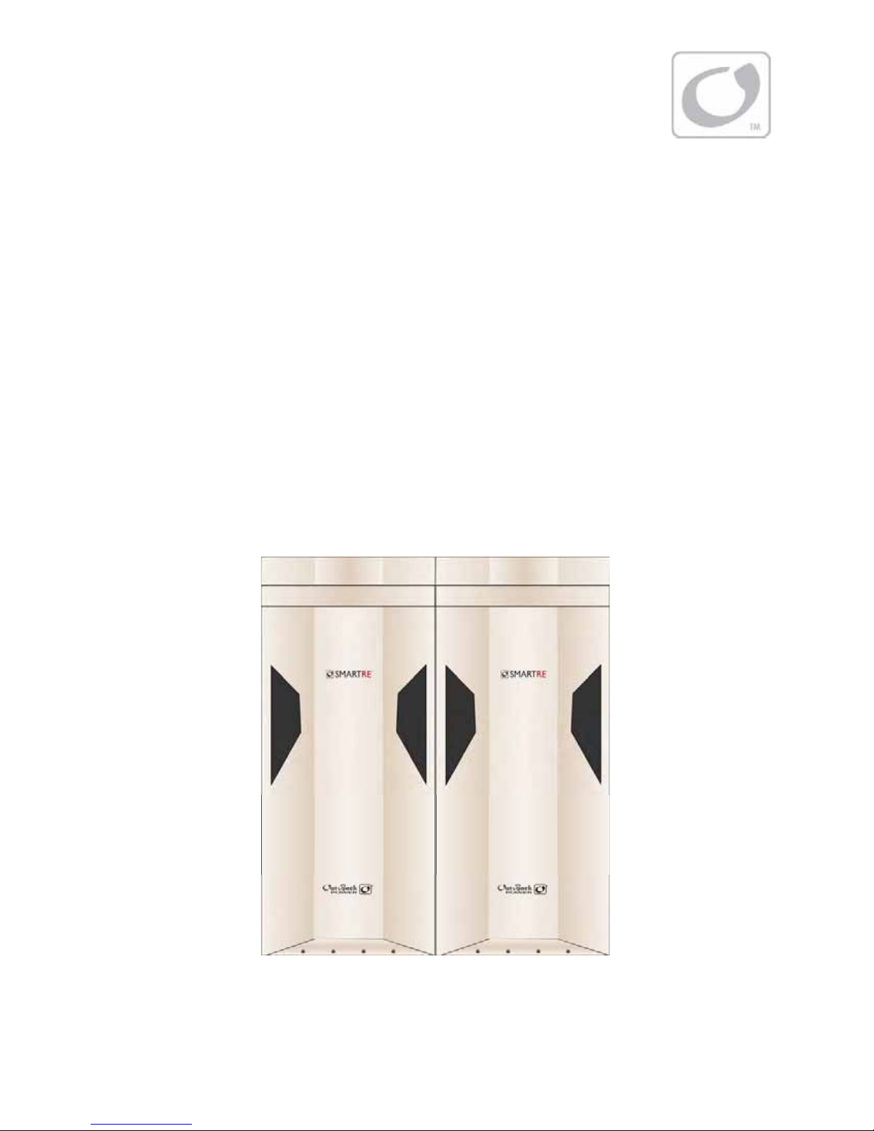
Figure 1 SmartRE 3000 with Top Caps and Front Covers....................................................................................................11
Figure 2 Basic Components of a SmartRE System .................................................................................................................12
Figure 3 Typical Grid-Interactive Application..........................................................................................................................13
Figure 4 Flexibility of Installation ................................................................................................................................................15
Figure 5 Clearance and Access Requirements ........................................................................................................................16
Figure 6 Enclosure Dimensions....................................................................................................................................................17
Figure 7 Conduit and Knockout Preparation...........................................................................................................................18
Figure 8 Horizontal versus Vertical Arrangements................................................................................................................20
Figure 9 Mounting Options (Wall Brackets or Anchor Bolts)..............................................................................................21
Figure 10 Mounting to the Wall at Floor Level..........................................................................................................................22
Figure 11 Mounting to the Wall above Floor Level .................................................................................................................23
Figure 12 Installing Wall Brackets for Vertical Position...........................................................................................................24
Figure 13 Interlocking Enclosures onto Wall Brackets............................................................................................................25
Figure 14 Correct Placement for Vertical Installations............................................................................................................26
Figure 15 Removing the Interior Cover .......................................................................................................................................27
Figure 16 Wiring and Breaker Compartment.............................................................................................................................28
Figure 17 Ground Connections ......................................................................................................................................................29
Figure 18 DC Connections................................................................................................................................................................30
Figure 19 AC Connections................................................................................................................................................................31
Figure 20 MATE2 Features................................................................................................................................................................32
Figure 21 MATE2 Dimensions (Not to Scale)..............................................................................................................................32
Figure 22 Permanently Connecting the MATE2 to the SmartRE.........................................................................................33
Figure 23 Temporarily Connecting the MATE2 to the SmartRE ..........................................................................................34
Figure 24 Functional Test Procedures..........................................................................................................................................35
Figure 25 MATE Setup Screen (Page 1)........................................................................................................................................36
Figure 26 MATE Setup Screen (Page 2 and 3)............................................................................................................................37
Figure 27 Accessing the Advanced Menus.................................................................................................................................38
Figure 28 Configuring System Parameters.................................................................................................................................39
Figure 29 Shutdown Procedures....................................................................................................................................................40
Figure 30 Reassembling the Electronics Enclosure .................................................................................................................41
Figure 31 Adding the Front Cover Bracket to the Electronics Enclosure .........................................................................41

Table of Contents
10 900-0033-01-00 Rev A
Figure 32 Reassembling the Battery Enclosure.........................................................................................................................42
Figure 33 Adding the Front Cover Bracket to the Battery Enclosure.................................................................................42
Figure 34 Installing the Top Cap ....................................................................................................................................................43
Figure 35 Installing the Locking Bracket .....................................................................................................................................43
Figure 36 Installing the Front Cover .............................................................................................................................................44
Figure 37 Vertical Installation using an External Sub-panel .................................................................................................55
Figure 38 Vertical Installation using the Internal Sub-panel ................................................................................................56
Figure 39 Horizontal Installation using an External Sub-panel ...........................................................................................57
Figure 40 Horizontal Installation using the Internal Sub-panel...........................................................................................58
Figure 41 Horizontal Installation using the Internal Sub-panel...........................................................................................59
Figure 42 Wiring Schematic for 2500 W and 3000 W, 120 Vac Configurations..............................................................60
Figure 43 Wiring Schematic for 2500 W and 3000 W, 120/240 Vac Configurations.....................................................61
900-0033-01-00 Rev A 11
Introduction
Thank you for using a SmartRE™ from OutBack Power Systems. SmartRE is an integrated grid-
interactive solution designed to be quick to install and easy to use.
The SmartRE System is intended for grid-interactive applications up to 6 kW in North America. It is
intended for use with photovoltaic (PV) modules for harvesting energy and a battery bank for energy
storage. SmartRE is certified as “Grid-interactive” meaning that excess energy (energy that exceeds
usage) will be returned to the Grid (Sell Mode).
The SmartRE System is designed with the following features:
¾2500 W, 3000 W, 5000 W, and 6000 W units
¾120 Vac-60 Hz and 120/240 Vac-60 Hz configurations
¾Rated for Indoor and Outdoor Installations
¾Includes chassis mounting brackets and interconnecting mounting brackets for wall-mounting
¾Uses MPPT technology to maximize the harvest from solar modules
¾ETL listed to UL1741
Figure 1 SmartRE 3000 with Top Caps and Front Covers
Introduction
12 900-0033-01-00 Rev A
Components
A complete SmartRE is comprised of the following components depending on the model selected.
Components can be purchased as complete systems or individually.
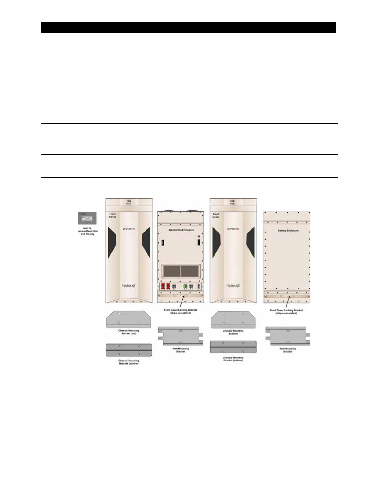
Table 2 Basic Components of a SmartRE System
Quantity Provided with….
Component SRE-2500-120-NA, SRE-2500-
120/240-NA, SRE-3000-120-NA,
SRE-3000-120/240-NA
SRE-5000-120/240-NA,
SRE-6000-120/240-NA
Electronics Enclosure 1 2
Battery Enclosure 1 2
Front Cover, Top Cap, and Front Cover Bracket12 each 4 each
Chassis Mounting Brackets (top and bottom) 2 each 4 each
Wall-Mounting Bracket (for 16” wall studs) 2 each 4 each
MATE2 System Control and Display 1 1
SmartRE Installation Manual (not shown) 1 1
SmartRE Operator’s Manual (not shown) 1 1
Figure 2 Basic Components of a SmartRE System
Accessories
The following accessories are available for purchase.
¾Wall-Mounting Bracket (for 24” wall studs)
¾Battery Installation kit(s) - provides cabling for specific battery types
¾Battery Enclosure Paralleling kit(s) – provides the hardware to connect two battery enclosures in parallel.
1Installation of these components are required for the 3R Rating. May be purchased separately as an accessory.
T
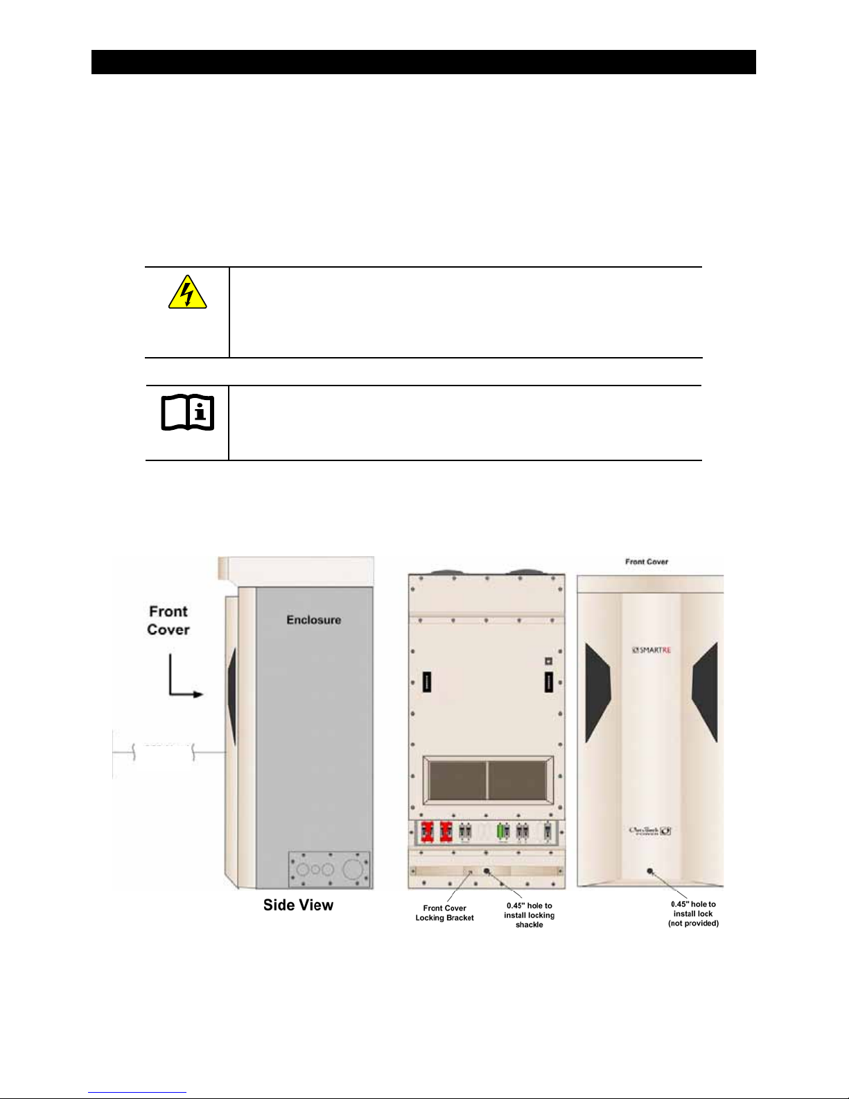
he Front Cover
Locking Bracket and
the Front Cover have
a 0.45” (1.1 cm) hole
to accommodate a
0.45” (1.1 cm)
standard lock. Locks
can be purchased
from any reputable
locksmith or
hardware store.
900-0033-01-00 Rev A 13
Planning
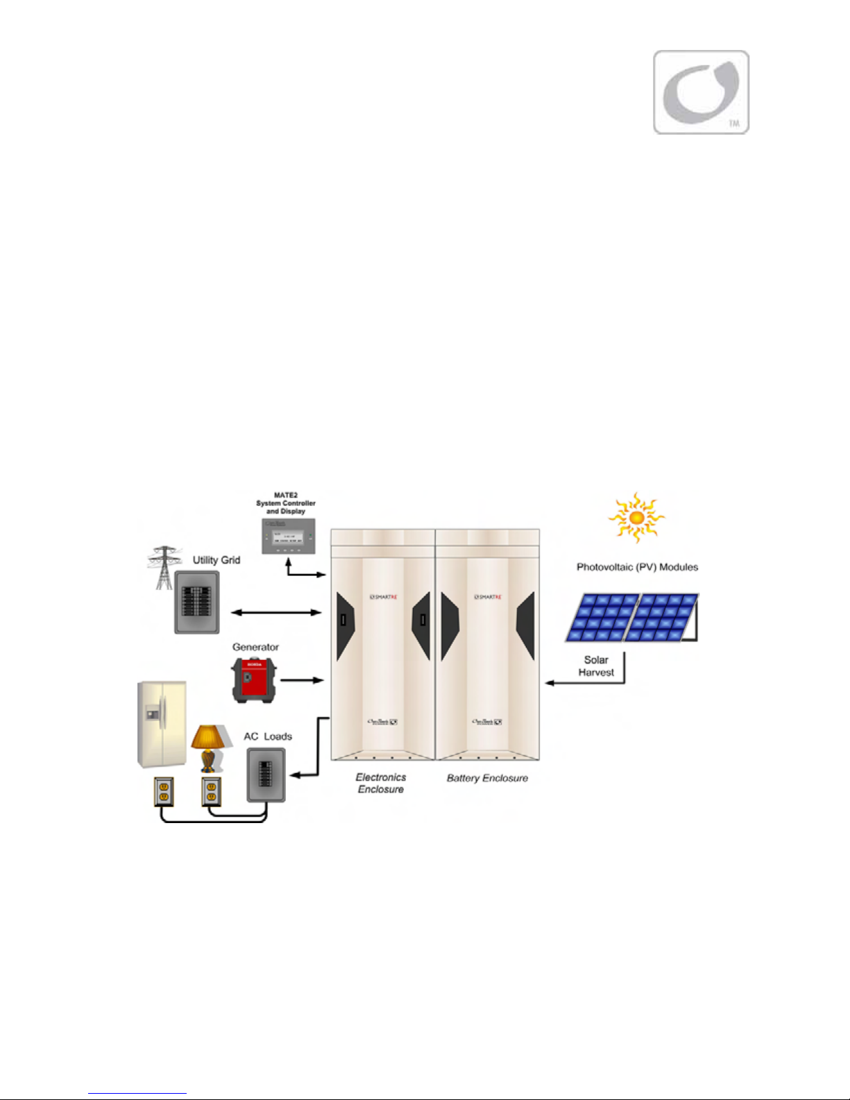
Applications
The SmartRE is intended for grid-interactive applications using photovoltaic (PV) panels to harvest
solar energy and a battery bank to store the harvested energy. The SmartRE has AC input terminals
which connect it to the utility grid, and AC output terminals which connect it to a "critical load"
subpanel for backup power. Normally grid power is transferred from the input directly to the output,
to run the critical loads. When excess PV is available from the batteries, the SmartRE supports those
loads with the PV. When the PV exceeds the load requirements, the SmartRE sells that excess power
back through its input, to the utility grid. When the utility grid is not available, the SmartRE takes over
to run the critical loads with PV and energy stored in the battery bank.
SmartRE models include:
¾SRE-2500-120-NA – 2500 W, 120 Vac/60 Hz ¾SRE-3000-120/240-NA – 3000 W, 120/240 Vac/60 Hz
¾SRE-2500-120/240-NA – 2500 W, 120/240 Vac/60 Hz ¾SRE-5000--120/240-NA – 5000 W, 120/240 Vac/60 Hz
¾SRE-3000-120-NA – 3000 W, 120 Vac/60 Hz ¾SRE-6000-120/240-NA – 6000 W, 120/240 Vac/60 Hz
Figure 3 Typical Grid-Interactive Application
PV Array Planning
The SmartRE is designed to use PV input to charge the battery bank. The FLEXmax 80 charge
controller(s) integrated into the SmartRE System uses Maximum Power Point Tracking (MPPT)
technology to maximize the PV harvest. A PV Combiner box (not included) may be required for
multiple PV strings. PV Combiner Boxes are available from OutBack Power Systems for 8 to 12
PV strings.
Maximum PV input voltage:
150 Vdc VOC including maximum
voltage temperature correction.
Maximum PV operating voltage:
145 Vdc VOC including maximum
volta
g
e tem
p
erature correction.

Planning
14 900-0033-01-00 Rev A
SmartRE models may include up to two PV inputs. Each PV input can support the following PV
configuration:
¾4,000 WSTC
¾150 VOC including local temperature correction factor per NEC 690.7
¾64 A ISC maximum PV array current per NEC 690.8
For a PV Planning Tool, see the following website.
http://outbackpower.com/resources/string_sizing_tool/
Battery Bank Planning
Types of Batteries
¾The SmartRE System supports 48 Vdc battery banks.
¾Group 27, Group 31 or Tall Group 31 batteries are recommended for use with this system.
¾One battery enclosure is designed to hold four Group 27, four Group 31 sealed batteries, or four Group 31
Tall sealed batteries.
Table 3 Recommended Batteries for use with the SmartRE2
Manufacturer Model Number Manufacturer Model Number
DC110-12 24-AGM
FULLRIVER DC220-6 27-AGM
EV12A-A 31-AGM
EV27A-A
Trojan
6V-AGM
EV31A-A PSG-12120
Discover
EV627A PSG-12105
PVX-1040T
Power Battery
PSG-12165
PVX-1080T 8A27DT-DEKA
PVX-3050T
MK/Deka
8A31DT-DEKA
PSG-12105
Concorde
PSG-12165
Battery installation kits are available to support the battery types listed in Table 3. The kits will provide
the cabling only. Batteries must be purchased separately.
Bank Sizing
In general, the size of the loads (watts) and the required backup period (hours) will determine best size
for the battery bank. To calculate this, use the information provided on page 47 through page 51.
Worksheets are provided for assistance.
Generators
In the absence of the grid, the following Honda™generators can be used with the SmartRE. However,
all the available features may or may not be useable. Consult with Tech Support at OutBack Power
Systems If necessary.
¾EU1000iA ¾EU3000iA
¾EU2000iA ¾EU6500iSA
2This list may be updated and expanded frequently. For an updated list, check www.outbackpower.com.

Planning
900-0033-01-00 Rev A 15
Preparation
Tools Required
The following tools may be required for installing this equipment.
¾Wire cutters/strippers ¾Drill and drill-bits
¾Torque wrenches ¾Ratchet drives
¾Assorted insulated screw-drivers ¾Digital Voltmeter
Materials Required
The following materials may be required for installing this equipment.
¾Conductors for wiring
¾Conduits, bushings (Rain-proof connectors must be used for 3R Rating if installed outdoors)
¾Anchor Bolts (x4) or Dry-wall (x6) screws for mounting.
¾Plywood for additional wall support or concrete to make a platform to sit the unit on. (Optional)
Accessories
The following accessories are available.
¾MATE2 System Controller and Display (included)
¾Remote Temperature Sensor (included)
¾Front Cover, Top Cap and Front Cover Locking Bracket
(Required for 3R Rating. May be purchased separately)
The following accessories are available for purchase.
¾Battery Enclosure Paralleling Kits
¾Wall-Mounting Bracket for 24” wall studs
¾Battery Installation Kits
Location
¾SmartRE is rated for indoor and outdoor installations.
The Front Cover, Top Cap and Locking Bracket are required
for outdoor installations.
¾SmartRE enclosures can be arranged horizontally or
vertically depending on the installation space that
is available. The SmartRE can be wall-mounted,
platform mounted, or stacked.
¾Only two modules can be stacked in a vertical
arrangement. Sets of stacked modules can sit side-by-
side. Ensure the location can support all the weight of
multiple systems. Battery enclosures must be floor/pad
mounted only.
¾In areas where seismic activity is a concern, consult
local code for seismic safety requirements. Horizontal
arrangements may be preferred using the wall-mounting
brackets for stability.
Figure 4Flexibility of Installation
Vertical
Arrangements
Horizontal Arrangements
Planning
16 900-0033-01-00 Rev A
Environmental
¾This unit is rated for 25°C (77°F). Exposure to extreme hot temperatures can affect the unit’s performance.
When used in an outdoor installation, use a shading structure to avoid direct exposure to sunlight.
¾The mounting surface should be level and able to support three (3) times the weight of the enclosure. This
may require additional support for wall-mounted installations.
Clearance and Access Requirements
WARNING: Fire/Explosion Hazard
Do not place combustible or flammable materials within 12 feet (3.7 m) of
the equipment. Fumes or spills from flammable materials could be ignited by
sparks created by sub-standard wiring conditions.
IMPORTANT:
Clearance and access requirements may vary by location. Consult local electric
code to confirm clearance and access requirements for the specific location.
Maintain a 36” (0.91cm) clear space in front of the enclosures for access. To restrict access, a 0.45” hole
is provided on the Front Cover and the Front Cover Locking Bracket to accommodate the installation
of a standard lock.
Figure 5Clearance and Access Requirements
36” (0.91 cm) Clearance
required in front of the
enclosures
36” (0.91 cm)

Planning
900-0033-01-00 Rev A 17
Dimensions
Figure 6Enclosure Dimensions

Planning
18 900-0033-01-00 Rev A
Conduit and Knockout Preparation
Knockouts are provided on the top and bottom of the enclosures, and on both sides of the enclosures.
Bushings are recommended to prevent damage to conductors from sharp edges along knockout
holes. The rectangular knockout panel on the side can be removed and used as a hand-hold to lift the
enclosures into place. Remove the knockouts from this panel while it is attached to the side of the
enclosure to prevent damaging or bending the panel when removing knockouts.
IMPORTANT:
For 3R compliance, use rain-tight conduit connectors.
Figure 7 Conduit and Knockout Preparation
3/8” (1 cm) holes (x4) in corners of the bottom of
the enclosures provide a place for either anchor
bolts or leveling feet (not provided).
For 3R Rating:
If the Chassis
Mounting Brackets
are NOT going to be
used, then install the
bolts (x6) that were
provided for use with
the mounting
brackets.
This manual suits for next models
3
Table of contents
Other OutBack Power Power Supply manuals


Popular Power Supply manuals by other brands


Puls
Puls PIANO Series manual

TELECO AUTOMATION
TELECO AUTOMATION AL-24-150WNT instructions

CEA
CEA EA3000-3072Wh-1BK Product instruction manual

Intel
Intel ATX Design guide

Alpha Technologies
Alpha Technologies APP 9022S Installation and operation manual

CAMPAGNOLA
CAMPAGNOLA Li-Ion 700 Use and maintenance manual


