CEA EA3000-3072Wh-1BK Specification sheet

Portable Power Station
Model NO: EA3000-3072Wh-1BK
Product Instruction Manual
Please read the instructions carefully before use and follow the instructions
CEA Electric Co., Ltd

1
CONTENT
Ⅰ、Product Use and Function Introduction .......................1-2
Ⅱ、Product Introduction .......................................3-10
1.Product Main Structure Composition ........................... 3
2.Panel Function Description ................................. 3-5
3.Display Interface Description ............................. 5-10
Ⅲ、Technical Parameters ......................................... 11
Ⅳ、Operation and Usage .......................................... 12
1. Steps for the First Start of Portable Power Station ........ 12
2.Charging Steps .............................................. 12
3.AC Output Onload Usage ...................................... 13
4.DC/USB Output Onload Usage .................................. 13
5. Expandable Battery Usage ....................................13
Ⅴ、Fault Code Comparison Table ...............................14-16
Ⅵ、Product Maintenance .......................................... 17
Ⅶ、Common Troubleshooting ....................................17-19
Ⅷ、Warnings and Precautions ..................................20-22
Ⅸ、Product Packaging List .......................................23

1
I、Product Use and Function Introduction
Product Name:Potable Power Station
Model/Specification:EA3000-3072Wh-1BK
Application and Function Introduction:Transform LiFePO4 DC to AC
sine wave by inverter. When the product is out of power, it can be
charged by mains and PV. Without Mains, this product can output AC to
charge devices with corresponding power such as fridges, electric
hammers, induction cookers, rice makers, fans, washing machines, TV,
and air-conditioner. This product supports PV charging while
discharging. Its structure meets UL2743 standards and can replace the
gasoline generator for outdoor emergency work on rainy days. The
product supports six expandable external batteries at maximum,
reaching 35.84KWH with a more durable loaded application. This product
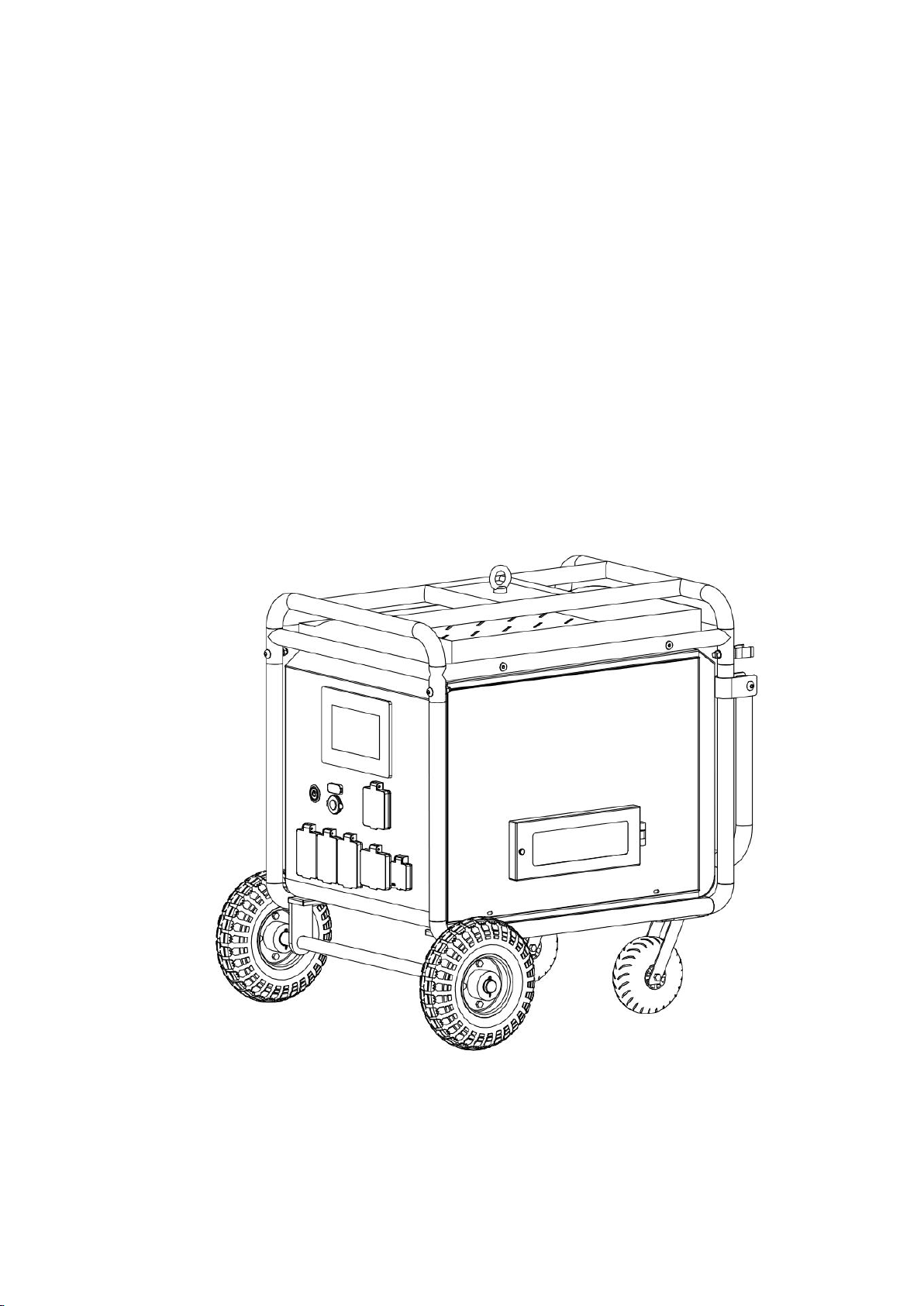
is equipped with two 10-inch foam wheels and two 7-inch universal
wheels with brakes, making it to be moved easier. On top of the product,
we designed a hook for safe lifting and handling. Besides, boxes on
the top and side allow users to put tools and accessories in outdoor
works. The main screen is a 7-inch high-resolution capacitance touch
screen with characteristics like anti-glare, high-definition, and
high sensitivity. All port covers are plastic. All output AC sockets
are independently installed with overload, short circuit protectors,
and the GFCI leakage protection socket to avoid safety risks during

2
the use. The product has functions like output overload, short circuits,
and high temperature.

3
II、Product Introduction
1. Product Main Structure Composition
The portable power station is mainly composed of a metal protection
frame, metal shell, PV reverse control machine, touch screen, USB/DC
panel, LiFePO4 battery, and other main accessories.
2. Description of Panel Functions
2.1 Front Panel
2.2 Rear panel

4
2.3 Left Door
2.4 Right Door
Cooling Window
AC Charging Input
Socket 20A
PV Charging Input
Socket
Expandable Battery
Interface
Ground Post

5
3. Display Interface Description
3.1 Home Page
3.2 Battery Information Page
Total Battery Level and Expandable
Battery Information Button
Remaining
Charging Time
Remaining Time
on Load
Charging Input
Status and
Parameters Page
Button
Load Output
and Parameters
Page Button
DC/USB
Output Switch
AC Output
Switch
Back Home
Button
Parameter Setting Button

6
The battery includes five status:1. Disconnected,2. Standby: the battery
is connected and on standby,3. Charging: the battery is connected and
charging,4. Discharge: the battery is connected and discharged,5. Failure.
3.3 Charging Input Page
3.4 Load Output Page
Main Battery
Status
Expandable
Battery
Capacity and
Status
Main Battery
Power Level
Mains
electricity
input charging
PV input
charging
parameter
display
USB/DC Load
Output
Parameters
Display

7
3.5 Setup Page
3.6 Language Settings Page
AC Load Output
Parameters
Display
Return to Previous Page Button
Language Setting
Set the Screen
Sleep time
Touch Sound
Switch
Charging
History
Screen
Brightness
Setting
Fault Code
Display

8
The product supports three language settings: English, French, Spanish
(the default setting is English);
3.7 Screen Sleep Time Page
There are four Settings for the off time: 30 seconds, 1 minute, 5 minutes,
and never (the default setting is 5 minutes);
3.8 Charging History Page

9
The charging history record will save the charging capacity record of the previous seven
days, and display the record according to the total charging power (Ah) of each day.
In that case, only the data of seven days is displayed.
3.9 The Fault Icon Instructions
Fault icons are divided into high temperature, short circuit, and overload. If the product
is in an abnormal state, the corresponding fault icon will appear on the screen. If you
click the fault icon, there will be a troubleshooting prompt.
High-temperature
Fault Icon

10
3.10 Fault Code Display
The fault code can display four fault numbers at the same time, increasing from left to
right. See Chapter 5 (Failure Code description table) for details about the meaning of the
code.
Short Circuit
Fault Icon
Output Overload
Icon
Fault Code
Display

11
Ⅲ、Technical Parameters
Item
Parameter
Nominal Power
3KW
Nominal Power
6KW
On-load Motor Capability
2HP
Battery Parameters
LiFePo4 51.2V 60AH
Battery Expansion
Supports the parallel expansion of up to 6 battery
packs
Grid Connection
No
Product Size
840*750*872mm
Product Weight
121.5KG
Ambient Temperature Range
-10-40℃;Relative humidity:≤80% ;
Altitude≤2000m
Transport and Storage
Environment
Temperature:-15-55℃;
Relative humidity:≤93%(no condensation);
Atmospheric pressure:70kPa~106kPa
Input
PV Charging
60-120V 50A Support MPPT Tracking function
LP-28 Triangle Connector
Mains Charging
110-120V 60HZ 2200W 20ATriangular Socket
Output
USB-A*4 Output
Independent 18W output*4:5V3A 9V2A 12V1.5A
Support QC3.0/QC2.0/AFC/FCP/BC1.2/APPLE and other
fast charging protocols
USB-C*2 Output
Independent 100W Output*2:5V3A 9V3A 12V3A 15V3A 20V5A
Support PPS/PD/QC3.0/QC2.0/AFC/FCP/BC1.2/APPLE and
other fast charging protocols
DC Output
5521 interface*2,cigarette lighter socket*1 12V10A
AC Output
American standard socket L5-30*1 30A 125V 60HZ
AC Output
American standard socket TT-30R*1 30A,125V,60HZ
AC Output
American standard socket duplex GFCI 5-20R*3 20A,125V,
60HZ
Charging
Time
PV Charging
About 1.1H(3000W)
Mains Charging
About 1.4H(2200W)
Support PV charging while discharging; do not support mains charging while discharging

12
IV、Operation and Usage
1. Steps for the First Start of Portable Power Station:
1.1 Turn on all circuit breaker switches at the side door.
1.2 Check whether there is any visible damage to the appearance of the
station and whether the output interfaces are loose or damaged (If
abnormal conditions occur, stop using)
1.3 Fix the grounding post on the back of the station to the ground.
1.4 Press the “POWER” button on the front panel, and if the green light
comes on, it indicates that the startup has been successful. Observe
whether the battery on the screen is fully charged. When the battery level
is below 30%, it is recommended to fully charge it before use. When the
product is powered on, the AC output defaults to on, and the DC/USB output
defaults to off.
2. Charging Steps:
2.1 AC charging:First, confirm whether the mains grid voltage and
frequency are within the range of mains charging input parameters of
this product. Second, confirm that there is no load on the AC output
socket, and plug one end of the AC charging cable in the accessory into
the charging socket on the back of the power station. Then, check whether
the charging power and remaining charging time on the screen correspond
to the product parameters. During the charging process, the AC switch
on the screen must be in the“ON”state. Otherwise, it cannot be charged.

13
2.2 Solar photovoltaic charging:Please check the photovoltaic input
voltage range before charging. After confirming that the positive and
negative poles of the input interface correspond correctly to the
positive and negative poles on the product socket, insert the input
interface into the photovoltaic charging socket at the bottom left
corner of the power station. Then, turn on the POWER switch on the front
panel and check if the photovoltaic charging power and remaining
charging time displayed on the screen correspond to the product
parameters. During the charging process, the POWER switch must be turned
on. Otherwise, the product cannot be charged.
3.AC output On-load Usage:
AC on load: Before use, please check that the power range and voltage
range of the on-load electrical equipment should match the output
parameters of the equipment, and press the RESET button on the GFCI5-20R
socket to open it; Check whether the short-circuiters at the side doors
are all open. Insert the power plug of the loaded product into the output
socket at the front of the power station, and turn on the AC switch on
the front panel. The load should work normally. Check the output on-load
power parameters on the display screen.
4.DC/USB Output On-load Usage:
Before using the power station, please check that the voltage and the

14
corresponding parameter range of the on-load electrical device are
consistent with the power station. Insert the interface plug of the
on-load electrical device into the corresponding interface in the front,
and turn on the DC switch on the screen. The load should work normally.
Check the output on-load power parameters on the screen.
5.Expanding Battery Usage:
Ensure that the specifications of the expandable battery are the same
as those of the main battery. When the main and the expandable battery
are off, insert one end of the expandable battery cable into the battery
expansion port on the rear panel of the station and the other end into
the socket in the expandable battery. Then turn on the portable power
station and expandable battery switch in turn. Check whether the battery
status in the main display is in normal status, and the capacity
deviation range between the two batteries should be within 10% before
expansion (otherwise, the battery life will be reduced and other battery
failures will occur during use). The expandable battery can be charged
independently by the charger equipped with the machine, or can be
simultaneously charged by the mains and photovoltaic with the main
battery;.

15
V、Fault Code Comparison Table
Fault
Codes
Meaning
Description
01
BatVoltLow
Battery under-voltage alarm
02
BatOverCurrSw
Battery discharge average current overcurrent
software protection
03
BatOpen
Battery not connected alarm
04
BatLowEod
Battery under-voltage stop discharge alarm
05
BatOverCurrHw
Battery overcurrent hardware protection
06
BatOverVolt
Charge overvoltage protection
07
BusOverVoltHw
Bus overvoltage hardware protection
08
BusOverVoltSw
Bus overvoltage software protection
09
PvVoltHigh
PV overvoltage protection
10
PvBoostOCSw
Boost overcurrent software protection
11
PvBoostOCHw
Boost overcurrent hardware protection
12
SpiCommErr
SPI communication failure between master and
slave chips
13
OverLoadBypass
Bypass overload protection
14
OverLoadInverter
Inverter overload protection
15
AcOverCurrHw
Inverter overcurrent hardware protection
16
SlaChiReqShu
Slave chip requests shutdown fault
17
InvShort
Inverter short-circuit protection

16
19
OverTemperMppt
PV radiator over temperature protection
20
OverTemperInv
Over temperature protection of inverter heat
sink
21
FanFail
Fan failure
22
EEPROM
Memory failure
23
ModeNumErr
Model setting error
24
Busduff
Positive and negative bus voltage imbalance
25
BusShort
Bus short circuit
26
RlyShort
Inverted AC output backflow to bypass AC
output
28
LinePhaseErr
Mains input phase error
29
BusVoltLow
Bus voltage low protection
30
BatCapacityLow1
Battery capacity rate below 15% alarm
31
BatCapacityLow2
Battery capacity rate below 5% alarm
32
BatCapacityLowStop
Battery low capacity shutdown
58
BMSComErr
BMS communication failure
59
BMSErr
BMS error
60
BMSUnderTem
BMS low temperature alarm
61
BMSVoerTem
BMS over temperature alarm
62
BMSOverCur
BMS overcurrent alarm
63
BMSUnderVolt
BMS under-voltage alarm
64
BMSOverVolt
BMS overvoltage alarm

17
Ⅵ、Product Maintenance
6.1 Newly purchased products should be fully charged before use;
6.2 Regularly remove dust and dirt from the cooling window;
6.3 In the case of long-term storage for more than three months, not less
than 50% of the power storage shall be maintained;
6.4 If stored for more than 6 months, to extend the service life of the
battery, please charge and discharge the product 1-2 times;
6.5 Regularly add wheel lubricant;
6.6 Scrub the surface of the chassis after each outdoor use;
6.7 Regularly check whether the external screws and lifting rings of the
chassis are fully tightened;
Ⅶ、Common Troubleshooting
7.1 Unable to Perform Mains Charging:
A、If the mains input voltage range and frequency exceed the parameter
range of the power station, it cannot be charged.
B、The AC switch in the screen should be in the open status. If the AC
switch is closed, it cannot be charged.
C、Check whether the specifications and models of the charging cable are
consistent with those equipped with this power station and check whether
there is an open circuit.

18
D、When charging, the AC output socket should not be plugged into the load,
otherwise, it cannot start charging.
7.2 Unable to Perform Photovoltaic Charging
A、Check whether the voltage range and current of the photovoltaic panel
are within the parameter range of the power station.
B、Make sure to use it in sufficient light.
C、Before PV charging, the POWER switch should be turned on first so that
the power station can be charged under the startup state.
D、Check whether the photovoltaic circuit breaker out of the side door
is open.
E、Check whether the positive and negative poles of the photovoltaic panel
connection line correspond to those on the product socket, and the plug
and socket should match.
F、Check whether the photovoltaic panel connection line has broken or is
in an open circuit situation;
7.3 Unable to Perform AC load::
A、Check whether the AC icon button in the display is open.
B、The circuit breakers at the side door of the product should all be turned
on.
C、The RESET button on the GFCI5-20R socket should be turned on and the
green indicator should be lighting.
Table of contents
Other CEA Power Supply manuals