Outdoor Water Solutions Windmill Pheasants Forever User manual

Customer Service: 1-866-471-1614
Website: www.outdoorwatersolutions.com
Springdale, Arkansas 72764
Phone: 1-866-471-1614 • Fax: 1-479-750-9178
Pheasants Forever / Quail Forever
Small Backyard Windmill™
Installation Manual
®

Thank you for purchasing an Outdoor Water Solutions Backyard Windmill™. We designed
this traditional style windmill with the same great engineering as our full-size aeration
windmills.
The following is the complete manual for the assembly of the OWS Backyard Windmill™,
company contact information, and a copy of our 1-Year Workmanship and parts Warranty.
CAUTION
1. DO NOT climb the tower. The head can turn without warning and is very dangerous. DO NOT use the
tower cross members as steps, as they cannot support your weight. The recommended method to service the
windmill is to lay the tower on its side.
2. DO NOT attempt to repair or service the windmill on a very windy day. It is too unpredictable and
dangerous, and you could easily be injured. Even in low winds, be very careful when servicing. Be certain
that the blade is securely tied before beginning any work.
3. ALWAYS teach children about the dangers of the windmill and keep them away from it.
4. Keep your distance from the windmill in thunder, strong winds, and lightning storms.
IGNORING THESE SAFETY WARNINGS
CAN RESULT IN SERIOUS INJURY OR DEATH
Package Contents:
Ensure that all components are included prior to beginning assembly.
Outdoor Water Solutions, Inc. Installation Manual
Small Backyard Windmill™ Page 1 of 7
Item Quantity Item Quantity
Tower Cone 1 Hardware Package Contents:
Decorative Maintenance Platform 1 L-Bracket 4
Tower Top Leg 4 Anchor Bracket 4
Tower Leg 4 Tail Fin Bracket 1
12” Cross Member 4 Nut & Bolt Package Contents:
21½” Cross Member 4 Push nut fastener 1
157⁄8” Cross Brace 8 ¼" x ½" Bolt 16
23½” Cross Brace 4 ¼" x ¾"Bolt 16
27¼” Cross Brace 4 ¼" Nuts 32
Tail Arm 1 ¼" Washer 16
Tail Fin 1 ¼" x 1" Bolt 4
27” Fan with Bearing 1 ¼" x 1½" Bolt 4
Head Connection Bracket 1 Pivot Tube Washer 1
Pivot Tube 1
!

Figure 1:
Tower Cone (1)
¼" x½" bolts; ¼" washers
Decorative Maintenance Platform (1)
& ¼" x ½" bolts with nuts (4)
Tower Top Leg (4)
12” Cross Member (4)
¼”
x ¾" bolts with nuts (16)
(to be used for all Leg connections)
157⁄8” Cross Brace (8)
Tower Leg (8)
¼” x½” bolts with nuts (4)
(to be used for all Cross
Brace “X” centers) (Pre-Assembled)
27¼” Cross Brace (4)
23½” Cross Brace (4)
Cross Brace Tensioning System,
Eye Bolt (4), 5/16" x ½" bolts (4),
L-Brackets (4), ¼" nuts (8),
& 5/16” Flange Nuts (4)
(Pre-Assembled)
21½” Cross Member (4)
Stake Clamps (4) and ¼" x 1"
bolts with nuts (4) (to tighten the
stake clamps around the stakes)
Outdoor Water Solutions, Inc. Installation Manual
Small Backyard Windmill™ Page 2 of 7
Decorative Maintenance
Platform Installation
Leg Connection, Backside View
Anchor Bracket Installation

Outdoor Water Solutions, Inc. Installation Manual
Small Backyard Windmill™ Page 3 of 7
TOWER SETUP INSTRUCTIONS
IMPORTANT NOTES:
• Unlessdirectedotherwise,donotcompletelytightenanyboltsuntilyourtowerisfullyassembled.
• Whenconnectinglegsections,alwaysensurethatthelowerlegsectionisbehindthetoplegsection.
• Therearetwodifferentstylesoftowerleg.Thelegswiththeholespunchedinonesideareforthetop
section; these holes are used to install the decorative maintenance platform.
1.
Begin the tower at the very top. Take the four tower top legs and fasten them to the tower cone with the eight
¼" x ½" bolts and ¼" washers, ensuring that the holes in the tower top legs are toward the top of the tower and
are across from each other (see Figure 2). If this is not done, the entire top section will need to be taken apart and
reassembled, in order to install the decorative maintenance platform. Completely tighten all of these bolts.
2. The next step is to build out the next section of the windmill. First, set the next leg section on top of the one above so
the top overlaps the bottom leg. (See Figure 3.)
Insert a ¼" x ¾"bolt thru the holes, then the one of the 15 7/8” short cross braces from the 4 cross brace
assemblies. (See Figure 4.)
Nextputthe12”crossmemberontopofthecrossbraceandnallythenut.(SeeFigure5.)Dothesamefortheother
side. Do not fully tighten the nuts yet. Repeat this process for all four sides by turning the windmill over each time.
!
!
Figure 2
Figure 3
Figure 4
Figure 5
TIP: From this point on, it will be simplest to assemble the
tower while it is laying on its side. Assemble on a soft surface
(e.g., lawn, cardboard, drop cloth, etc.) to prevent scratching.
Holes for Maintenance Platform
3. The next step is to complete the tower in
essentially the same way. To do this, we need
tondtheanchorbracketsandinstalltheseon
the outside of the bottom leg with a ¼" x ¾"
bolt. (See Figure 6.) Make sure that the anchor
bracket is leaning outwards at the top as you’ll
need to install your anchor rods through the
bracket once the windmill has been assembled.

TOWER SETUP INSTRUCTIONS
Next insert the bottom of the cross brace assembly. You can start with the side that has the cross brace tensioner.
(See Figure 6.)
Theninsertthe21½”crossmemberandnallythenut(SeeFigure7.)Dothesamefortheremaining3sides.Itworks
best if the cross brace tensioner is always on the same side (either left or right). Do not tighten yet.
4. Next, stand the windmill up on a level surface and shake it a little so that everything adjusts to become level. Then
start at the 12” cross member and tighten those 8 bolts. Next, tighten the 8 bolts on the 21 ½” cross member. Next
tighten up the 4 bolts holding the cross braces together.
Lastly, adjust the tensioners so that you take out any unnecessary play in the cross braces.
Install the decorative maintenance platform using 4 of the ¼" x ½" bolts and nuts. (See Figure 9.)
You have now completed assembling the tower of your Backyard Ornamental Windmill.
Figure 9
Figure 6 Figure 7
Figure 8
Page 4 of 7
Outdoor Water Solutions, Inc. Installation Manual
Small Backyard Windmill™

Outdoor Water Solutions, Inc. Installation Manual
Small Backyard Windmill™ Page 5 of 7
WINDMILL HEAD INSTALLATION
IMPORTANT NOTES:
• Wheninstallingthetailarm,itisveryimportanttoensurethatoneendbuttsupagainstthefansupport
shaftweldedinsidetheheadconnectionbracketandtheotherendisushwiththebackofthetailn
bracket. If this is not done, the windmill may not track the wind properly.
• Ensurethatallboltsarecompletelytightenedthroughouttheheadassembly.
Figure 10: Tail Fin 27” Fan
24” 2.5”
Tail Fin Bracket
(reverse side)
Tail Arm
Head Connection Bracket
Pivot Tube
Fan
Support
Shaft
Figure 11:
Figure 12:
Pivot Tube
Washer
Plastic Tower
Top
1.
Installthetailnontothetailarmwiththetailnbracketandfour¼"
x ½" bolts and nuts, and eight washers, as shown in Figure 11.
IMPORTANT: Make sure that the end of the tail arm is
ushwithbackofthebracket.
2. Insert the other end of the tail arm into the head connection
bracket, until it butts up against the welded fan support shaft.
Once the tail arm is inserted completely, use one of the ¼" x 1½"
bolts and nuts to clamp the tail arm into place. Tighten the bolt
fully, to ensure that the tail arm cannot come out.
IMPORTANT: Make sure that the end of the tail arm butts
up against the fan support.
3. Insert the pivot tube into the head connection bracket, so that
the pivot tube is between the three remaining holes in the head
connection bracket, as shown in Figure 10. Securely tighten
all four bolts.
4.We STRONGLY recommend that you go ahead and install the pushnut
fastener that comes with each windmill. This helps secure and lock
the windmill head onto the shaft which is important for areas where
winds might exceed 30 mph. If you elect not to install the pushnut
fastener, you can simply insert the fan support shaft into the windmill
head or fan and tighten the two set screws as tight as possible. Then
insert the pivot tube through the pivot tube washer, then into the
plastic tower top as shown in Figure 12.
!
!
!

Outdoor Water Solutions, Inc. Installation Manual
Small Backyard Windmill™ Page 6 of 7
It can be a challenge to get the two set screws adequately tightened, especially in areas prone to higher winds.
Therefore we are including a pushnut fastener to help secure the windmill head to the windmill shaft. We strongly
recommend using this locking fastener as well as locking in the two set screws on the bearing collar to secure the
windmill head.
5. Remove the three nuts and bolts holding the bearing onto
the windmill fan. Next slide the rear bearing nest and bearing
onto the shaft. Lock bearing into place exactly 5/16” from the
end of the shaft as measured from the front of the bearing.
Securely tighten the 2 set screws on the rear of the bearing.
They need to really bite into the shaft to keep the windmill
headsecure.Usingplierstoturntheallenwrenchwillhelp.
(See Figure 13)
6. Set the windmill head on top of the bearing
and push the locking pushnut fastener down
on the shaft to seat.
It needs to slide all the way down to the
bearing. It might help to use a hammer and
atheadedscrewdrivertopushthewasher
onto the windmill shaft or you can use a
9/16” or 5/8” socket. (See Figure 14)
7. Now install the front bearing Hub to the windmill head
and the back bearing nest. Tighten the three bolts and
nuts securely and your good to go. (See Figure 15)
8. Insert the pivot tube through the pivot tube washer, then into the plastic tower, as shown in Figure 12.
Figure 13:
Figure 14:
Figure 15:
5/16”

WINDMILL ANCHOR INSTALLATION
IMPORTANT NOTE:
• OutdoorWaterSolutionsWindmills™willnotdeterminesoilandwindconditions
for any windmill installation. Therefore, these conditions must be determined by the
customer. Anchoring of the windmill tower is very important. It is the customer’s
responsibility to adequately anchor the tower. Outdoor Water Solutions, Inc.
supplies a basic anchoring kit with each unit. However, in certain circumstances —
such as light soil conditions and high-to-extreme wind areas — it may be necessary
to utilize other anchoring techniques. Concrete piling, concrete pads, or screw-in
anchors are some examples. The customer is responsible to anchor the windmill
adequately, or consult the appropriate people to do so.
• Readthroughthisentireprocedurepriortobeginning.
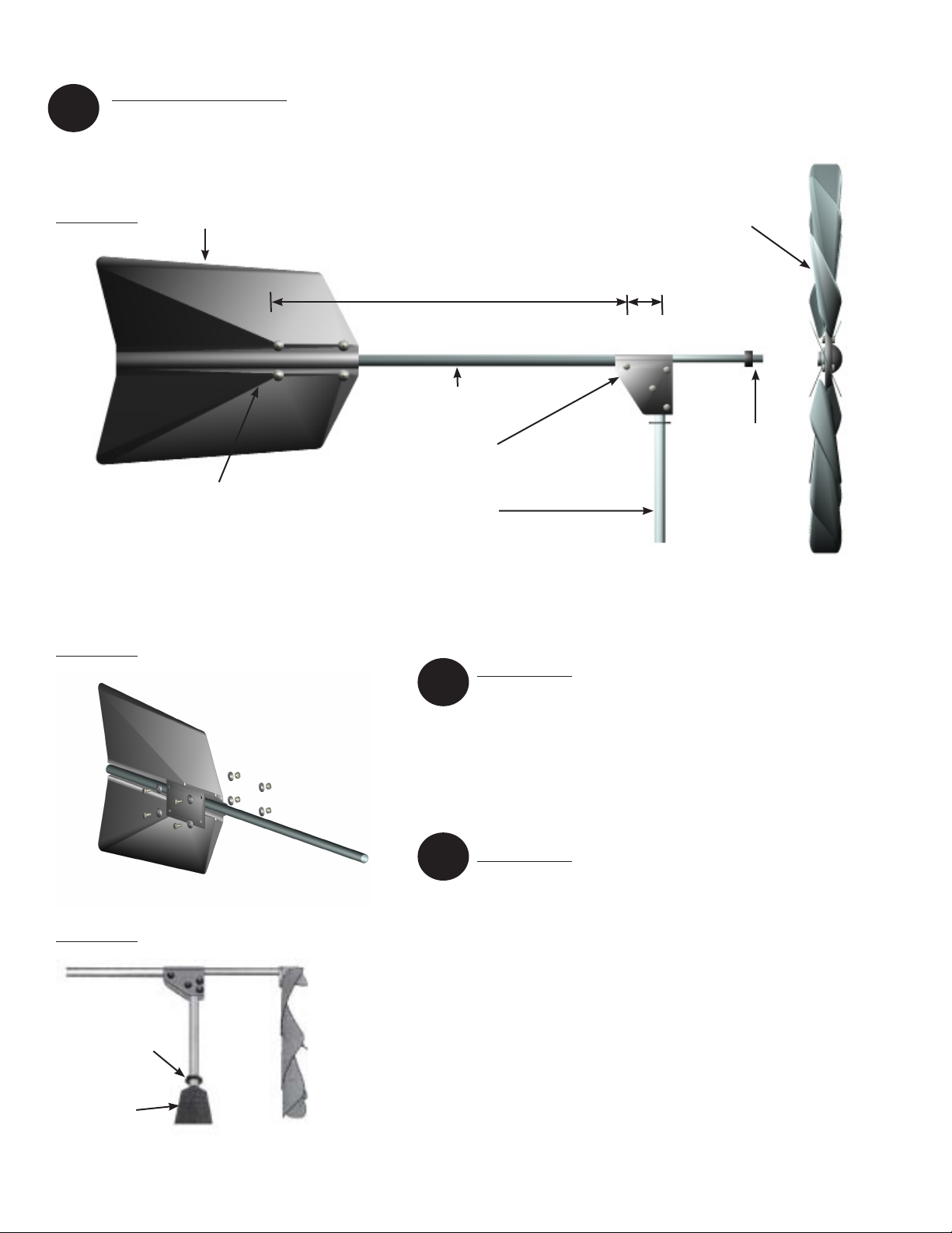
1. Choose an area in your yard (approximately 3’ x 3’) that is level, or close to level.
2. Stand the assembled windmill up on the location you have selected for installation.
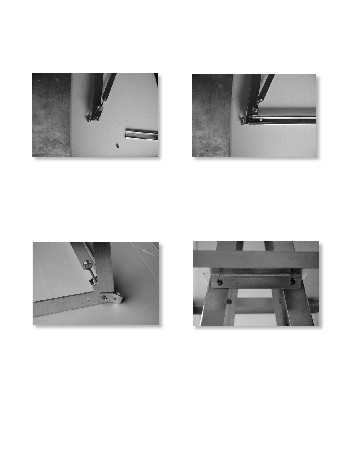
3. Drive the stakes into the ground through the anchor brackets. Make sure to leave the stake clamps at
approximately the same height, to simplify the leveling process.
4. Level the windmill as follows:
a. Starting with the highest leg, drive the stake until it is ¼” above the stake clamp, as shown in Figure 16. Tighten
the ¼" x 1" bolt in the stake clamp, to secure the leg to the stake.
b. Moving in a clockwise direction, move the stake clamp on the next leg to the top of the stake, leaving ¼”
above the stake. Tighten the ¼" x 1" bolt in the stake clamp, to secure the leg to the stake. Drive the stake into
the ground until the leg is level with the last secured leg.
c. Repeat ‘b.’ above, until the tower base is level.
The Outdoor Water Solutions One-Year Limited Warranty
Warranty covers all Outdoor Water Solutions Windmill™products for a period of one year from Date of Purchase,
against defects in workmanship or material. The conditions of the Warranty and the extent of the responsibilities of
Outdoor Water Solutions, Inc.™ under this Warranty are as follows.
1. Outdoor Water Solutions, Inc.™will repair or replace any part or material deemed to be defective by Outdoor Water
Solutions, Inc.™due to quality and/or workmanship, within a one-year period from the initial purchase date;
2.ProductreturnedforWarrantymustbereturnedtotheaddressspeciedbytheManufacturer,freightprepaid,andany
warranty product sent to the customer will be sent freight prepaid;
3. Warranty does not apply to product which has been subject to abuse, neglect, accident, or incorrect installation;
4. Warrantly does not apply to damage resulting from severe weather factors;
* Private Insurance Coverage is recommended *
5. If parts other than genuine Outdoor Water Solutions™ parts are utilized for repair or attached to an Outdoor Water
Solutions Windmill™system, warranty coverage may be void;
6. Proof of Date of Purchase is required for warranty service. Since the customer is responsible for assembly, setup, and
installation, please follow instructions carefully, to ensure the validity of warranty claims;
7. If you have any warranty concerns, please contact Outdoor Water Solutions, Inc.™at 1-866-471-1614
or 1-479-756-1614.
Outdoor Water Solutions, Inc.™recommends that, for future reference,
you keep this Installation Manual, along with your proof of
purchase and a photo of the windmill in a convenient location.
Date of Purchase: ____________________________
Outdoor Water Solutions, Inc. Installation Manual
Small Backyard Windmill™ Page 7 of 7
Figure 16
!
This manual suits for next models
1
Table of contents
Other Outdoor Water Solutions Lawn And Garden Equipment manuals
Popular Lawn And Garden Equipment manuals by other brands

Tiger
Tiger RBF-19C Operator's manual

Graf
Graf Carat S installation manual

plastia
plastia Urbalive Berberis DUO user guide

Cub Cadet
Cub Cadet Volunteer 4 x 4 EFI Camo Limited warranty

Quality Lifesciences
Quality Lifesciences MOSKITRAP FFN-302-2T instruction manual

Suncast
Suncast SRR1600 Assembly instructions