Outdoor Water Solutions Windmill User manual

Outdoor Water Solutions, Inc.
12’ Backyard Windmill™
Installation Manual
Customer Service: 1-866-471-1614
Website: www.outdoorwatersolutions.com
Springdale, Arkansas 72764
Phone: 1-866-471-1614 Fax: (479) 750-9178

Thank you for purchasing an Outdoor Water Solutions Backyard Windmill. We
designed this traditional style windmill with the same great engineering as our full size
aeration windmills.
Please find the complete manual for the assembly of the OWS Backyard Windmill,
company contact information and a copy of our 1 Year Workmanship and Parts Warranty.
CAUTION
1. DO NOT climb the tower. The head can turn without warning and is very dangerous. DO NOT
use the tower cross members as steps as they cannot safely support your weight. The recom-
mended method to service the windmill is to lay the tower on its side.
2. DO NOT attempt to repair or service the windmill on a very windy day. It is too unpredictable
and dangerous, and you could be easily injured. Even in low winds, be very careful when serv-
icing. Be certain that the blade is securely tied before beginning any work.
3. ALWAYS teach children about the dangers of the windmill and keep them away from it.
4. Keep your distance from the windmill in thunder, strong winds and lightning storms.
IGNORING THESE SAFETY WARNINGS CAN
RESULT IN SERIOUS INJURY OR DEATH
Package Contents:
Ensure that all components are included prior to beginning assembly.
Item Quantity Item Quantity
Tower Cone 1 Head Connection Bracket 1
Decorative Maintenance Platform 1 Pivot Tube 1
Tower Top Leg 4 Hardware Package Contents:
Tower Leg 8 L-Bracket 8
12” Cross Member 4Anchor Bracket 4
21 1/2” Cross Member 4 Tail Fin Bracket 1
31” Cross Member 4 Nut & Bolt Package Contents:
15 7/8” Cross Brace 8 Eye Bolt 8
19 1/2” Cross Brace 8 5/16” x 1/2” Bolt 8
24” Cross Brace 4 1/4” x 1/2” Bolt 24
25” Cross Brace 4 1/4” x 3/4” Bolt 24
27 1/4” Cross Brace 4 1/4” Nut 72
28 1/4” Cross Brace 4 1/4” Washer 16
Tail Arm11/4” x 1 1/2” Bolt 4
Tail Fin 1 1/4” x 1” bolt 4
27” Fan with Bearing 1 Pivot tube washer 1
5/16” Flange Nut 8
Outdoor Water Solutions, Inc. Installation Manual
12’ Backyard Windmill™ Page 1 of 6
!

Figure 1:
Outdoor Water Solutions, Inc. Installation Manual
12’ Backyard Windmill™ Page 2 of 6
Figure 2:
Tower Cone (1)
1/4” x 1/2” bolts, 1/4” washers and
nuts (8)
Decorative Maintenance Platform (1)
& 1/4” x 1/2” bolts with nut (4)
Tower Top Leg (4)
12” Cross Member (4)
1/4” x 3/4” Bolt with Nut (24)
(to be used for all Leg connections)
15 7/8” Cross Brace (8)
Tower Leg (8)
1/4” x 1/2” bolt with nut (8) (to be
used for all cross brace “X” centers)
Cross Brace Tensioning System,
Eye Bolt (8) 5/16” x 1/2” bolt (8), L-
bracket (8), 1/4” nuts (16) &
5/16” Flange Nut (8)
Stake Clamps (4) and 1/4” x 1” bolt
with nut (4) (to tighten the stake
clamps around the stakes)
27 1/4” Cross Brace (4)
24” Cross Brace (4)
21 1/2” Cross Member (4)
19 1/2” Cross Brace (8)
28 1/4” Cross Brace (4)
25” Cross Brace (4)
31” Cross Member (4)
Decorative Maintenance Platform
Installation
Leg Connection Backside
View
Anchor Bracket Installation
Figure 3:
Figure 4:

TOWER SETUP INSTRUCTIONS
IMPORTANT NOTES:
•Unless directed otherwise, do not completely tighten any bolts until your tower is fully assembled.
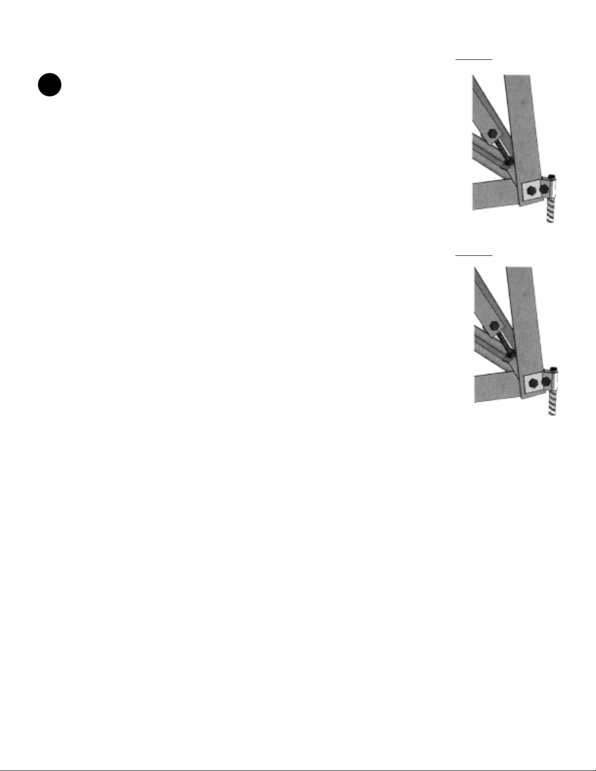
• When connecting leg sections always ensure that the lower leg section is behind the top leg section.
•There are two different styles of tower leg. The legs with the holes punched in one side are for the top sec-
tion; these holes are used to install the decorative maintenance platform.
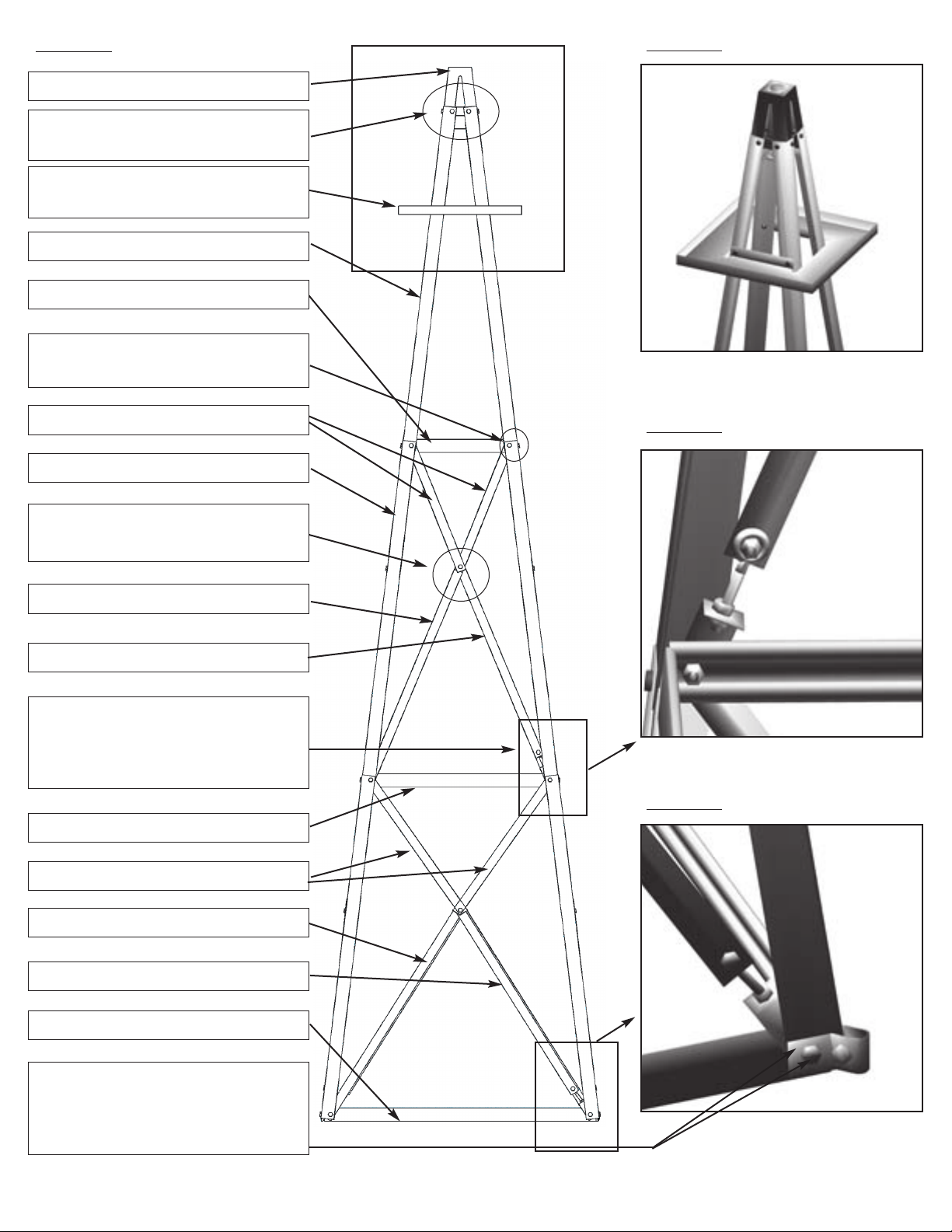
1. Assemble each of the cross brace support “X” sections for the middle and bottom sections for all four sides as shown in Figure
1. This includes the cross brace tensioning systems. The cross brace tensioning system consists of two (2) 1/4” nuts, one (1)
5/16” x 1/2” bolt, one (1) eye bolt, one (1) 5/16” Flange nut and one (1) L-bracket. The cross brace tensioning systems are to
be installed on the 24” and 25” cross braces only. When installing the cross brace tensioning “L” bracket, try to position all of
them at the same height on each of the eye bolts; this will simplify the squaring process later. Refer to figure 3 for further detail
on installing the cross brace tensioning systems on the 24” and 25” cross braces.
2. Begin the tower at the very top. Take the four tower top legs and fasten them to the tower cone with the eight 1/4” x 1/2” bolts,
1/4” washers & 1/4” nuts, ensuring that the holes in the tower top legs are toward the top of the tower and are across from
each other (see figure 2). If this is not done, the entire top section will need to be taken apart and reassembled in order to install
the decorative maintenance platform. Completely tighten all of these bolts.
TIP: From this point on, it will be simplest to assemble the tower while it is laying on its side. Assemble on a soft
surface (e.g. lawn, cardboard, drop cloth, etc.) to prevent scratching.
3. Install the middle section of each side using two 1/4” x 3/4” bolts, two legs, one middle section cross brace “X” (assembled in
step 1 above) and one 12” Cross Member. These parts should be attached to the top legs in the order just described from out-
side to inside. One nut can be then be placed onto each of the two bolts – do not completely tighten yet. Repeat this process
for all four sides. Refer to figure 1 and figure 3 for assembly illustrations.
TIP: Start with the side that is on the ground then complete the vertical sides then the top side. When working on
the sides that are not on the ground the 21 1/2” cross members can be installed temporarily using eight 1/4” x 3/4”
bolts and nuts to provide support and stability (see figure 1).
4. Repeat the process used in step 3 above to attach the bottom section. Make sure that the 27 1/4” cross braces and cross brace
tensioner L-brackets are included when connecting the bottom section parts to the middle section. They should be installed
between the 19 1/2” cross braces and the 21 1/2” cross member (see figure 1 and figure 3). Install the anchor brackets and 31”
cross member as part of this step. The anchor brackets should be installed first (see figure 4), then the leg, then the 28 1/4”
cross braces or L-bracket, then the 31” Cross Member. Insert the 1/4” x 1” bolt through the anchor bracket (see figure 4) but
do not tighten until the tower is erected in its final position and the stakes are driven through the clamps.
TIP: You will need to remove any 21 1/2” cross members temporarily installed in step 3 above in order to install the
bottom section.
TIP: You may need to loosen or tighten the L-brackets on the eye bolt in order to complete this step – try to loosen
or tighten all four L-brackets on each section equally.
5. Square up the middle section by adjusting the cross brace tensioners in the middle section. When all cross braces are tightened,
turn the nut above the L-bracket so that it is tight to the L-bracket. Repeat this process for the bottom section.
6. Install the Decorative Maintenance platform using four 1/4” x 1/2” bolts and nuts.
You have now completed assembling the tower of your Backyard Ornamental Windmill.
Outdoor Water Solutions, Inc. Installation Manual
12’ Backyard Windmill™ Page 3 of 6
!
!
!
!

WINDMILL HEAD INSTALLATION:
IMPORTANT NOTES:
•When installing the tail arm it is very important to ensure that one end butts up against the fan support
shaft welded inside the head connection bracket and the other end is flush with the back of the tail fin
bracket. If this is not done the windmill may not track the wind properly.
• Ensure that all bolts are completely tightened throughout the head assembly.
Figure 6
1. Install the tail fin onto the tail arm with the tail fin bracket and four 1/4” x 1/2”
bolts and nuts and eight washers as shown in Figure 6.
IMPORTANT:Make sure that the end of the tail arm is flush with back
of the bracket
2. Insert the other end of the tail arm into the head connection bracket until it
butts up against the welded fan support shaft. Once the tail arm is inserted
completely use one of the 1/4” x 1 1/2” bolts and nut to clamp the tail arm
into place as shown in figure 1. Tighten the bolt fully to ensure that the tail
arm cannot come out.
IMPORTANT:Make sure that the end of the tail arm Butts up against
the fan support shaft.
3. Insert the pivot tube into the head connection bracket so that the pivot tube is
between the three remaining holes in the head connection bracket as shown
in figure 5. Insert three remaining 1/4” x 1 1/2” bolts through the holes and
completely tighten the bolts.
4. Install the fan onto the Fan Support Shaft and tighten all of the set screws com-
pletely.
5. Insert the pivot tube through the pivot tube washer then into the plastic tower
top as shown in Figure 7.
Outdoor Water Solutions, Inc. Installation Manual
12’ Backyard Windmill™ Page 4 of 6
!
!
!
Pivot tube washer
Plastic Tower
Top
Tail Fin
24” 2.5”
Tail Arm
27” Fan
Head Conncection Bracket
Pivot Tube
Fan
Support
Shaft
Tail Fin Bracket
(reverse side)

WINDMILL ANCHOR INSTALLATION:
IMPORTANT NOTE:
• Outdoor Water Solutions Windmills will not determine soil and wind condi-
tions for any windmill installation. Therefore, these conditions must be deter-
mined by the customer. Anchoring of the windmill tower is very important. It
is the customer’s responsibility to adequately anchor the tower. Outdoor
Water Solutions, Inc. supplies a basic anchoring kit with each unit. However,
in certain circumstances, such as light soil conditions and high to extreme wind
areas, it may be necessary to utilize other anchoring techniques. Concrete pil-
ing, concrete pads, or screw in anchors are some examples. The customer is
responsible to anchor the windmill adequately or consult the appropriate peo-
ple to do so.
• Read through this entire procedure prior to beginning.
1. Choose an area in your yard (app. 3’ x 3’) that is level, or close to level.
2. Stand the assembled windmill up on the location you have selected for installation.
3. Drive the stakes into the ground through the anchor brackets. Make sure to leave the stake clamps
at approximately the same height to simplify the levelling process.
4. Level the windmill as follows:
a. Starting with the highest leg drive the stake until it is 1/4” above the stake clamp as shown in
Figure 8. Tighten the 1/4” x 1” bolt in the stake clamp to secure the leg to the stake.
b. Moving in a clockwise direction, move the stake clamp on the next leg to the top of the stake
leaving 1/4” above the clamp. Tighten the 1/4” x 1” bolt in the stake clamp to secure the leg
to the stake. Drive the stake into the ground until the leg is level with the last secured leg.
c. Repeat “b.” above until the tower base is level.
d. In order to eliminate any sharp points, Move the Stake clamps up the stakes until they are even
with the tops of the stakes as shown in Figure 9.
Congratulations! You have successfully installed
your Outdoor Water Solutions
12’ Backyard Windmill™.
Please contact us at 1.866.471.1614 or 479.756.1614 to order parts or for assistance in any step along the
way. We are also developing an aeration conversion kit that will convert your new 12' Backyard Windmill™
into a functioning aeration windmill.
Keep in mind that a 12' Backyard Windmill is a great gift and is available in a variety of colors along with our
galvanized steel options.
If you are interested in more information call today or visit us on the web www.outdoorwatersoltuions.com
Outdoor Water Solutions, Inc. Installation Manual
12’ Backyard Windmill™ Page 5 of 6
!
Figure 8
Figure 9

The Outdoor Water Solutions One Year Limited Warranty
Warranty covers all Outdoor Water Solutions Windmill products for a period of one year from Date of Purchase, against defects in
workmanship or material. The conditions of the Warranty and the extent of the responsibilities of Outdoor Water Solutions, Inc.
under this Warranty are as follows:
1. Outdoor Water Solutions, Inc.. will repair or replace, any part or material deemed to be defective by Outdoor Water
Solutions, Inc.., due to quality and/or workmanship, within a one year period from the initial purchase date;
2. Product returned for Warranty repair must be returned to the address specified by the Manufacturer freight prepaid, and any
warranty product sent to the customer will be sent freight prepaid;
3. Warranty does not apply to product which has been subject to abuse, neglect, accident or incorrect installation;
4. Warranty does not apply to damage resulting from severe weather factors;
* Private Insurance coverage is recommended *
5. If parts other than genuine Outdoor Water Solutions parts are utilized for repair or attached to a Outdoor Water Solutions
Windmill system, warranty coverage may be void.
6. Proof of Date of Purchase is required for warranty service. Since the customer is responsible for assembly, set up and instal-
lation, please follow instructions carefully, to ensure the validity of warranty claims;
7. If you have any warranty concerns, please contact Outdoor Water Solutions, Inc.. at 1-866-471-1614 or 479-756-1614.
Safety Precautions
1. Do Not attempt any service or repairs to the windmill with the blade turning or in any high wind situations;
2. Ensure the blade assembly is secured (even in low winds) when servicing or repairing of the windmill is required. (A gust of
wind can suddenly cause the windmill head to turn at any time and cause a potentially dangerous situation for the person
trying to do the repairs);
3. Do Not allow children to play on or near the windmill;
4. Avoid being near the windmill during thunderstorms.
Return Materials Authorization
•A return materials authorization (RMA) number must be obtained prior to returning any product for a warranty concern.
• You can call the OWS warranty department at the following number: 1-866-471-1614 or 479-756-1614
•We request that all returns be accompanied by a Return Materials Authorization (RMA) to help us track all warranty projects
and to ensure that your job is handled in a timely manner and that all freight costs are covered by OWS. Unauthorized return
shipments could result in return of product and freight costs not being covered.
Outdoor Water Solutions, Inc.. recommends that, for future reference,
you keep this Installation Manual, along with your proof of
purchase and a photo of the windmill in a convenient location.
Date of Purchase: _____________________
Outdoor Water Solutions, Inc. Installation Manual
12’ Backyard Windmill™ Page 6 of 6
Table of contents
Other Outdoor Water Solutions Lawn And Garden Equipment manuals
Popular Lawn And Garden Equipment manuals by other brands

ALBA-KRAPF
ALBA-KRAPF Royal Serie II Assembly instructions

Jumil
Jumil Exacta air 2980 PD Pantografica Operator's manual

Whitehouse
Whitehouse BEEHIVE BK-HPDH30 instruction manual

Sunforce
Sunforce 86115 manual

Tigercat
Tigercat M760 Operator's manual

Bush Hog
Bush Hog TOUGH Squealer SQ142 Specification sheet

Echo
Echo POWER PRUNER DPPT-2600H Operator's manual

Martha Stewart Living
Martha Stewart Living Snow-People Lawn Ornament Quick start quide

Bush Hog
Bush Hog RDTH Series Operator's manual

Garden Grow
Garden Grow G4445 instruction manual

New England Arbors
New England Arbors The Trellis Assembly instructions

Gardigo
Gardigo 62318 instruction manual