Output Technology LaserMatrix Floor Model Stacker Manual

LaserMatrix
LaserMatrixLaserMatrix
LaserMatrix®
®®
®
Floor Model Stacker
Floor Model StackerFloor Model Stacker
Floor Model Stacker
(Full Capacity Models LM1000A115 & LM2400A100)
Operator’s Guide
Operator’s GuideOperator’s Guide
Operator’s Guide
Part No: 066-00452-02
January 23, 1998 — Rev. G

COPYRIGHT
COPYRIGHTCOPYRIGHT
COPYRIGHT
1994, OUTPUT TECHNO
1994, OUTPUT TECHNO1994, OUTPUT TECHNO
1994, OUTPUT TECHNOLOGY CORPORATION
LOGY CORPORATIONLOGY CORPORATION
LOGY CORPORATION
All rights reserved under the Berne Convention.
TRADEMARKS
TRADEMARKSTRADEMARKS
TRADEMARKS
LaserMatrix is a registered trademark of Output Technology
Corporation.
PARTS AND SERVICE
PARTS AND SERVICEPARTS AND SERVICE
PARTS AND SERVICE
Contact Output Technology Corporation for parts and service. Have the
serial number of your printer and LaserMatrix Stacker handy so that we
can serve you more quickly.
We suggest you use genuine Output Technology Corporation supplies
and authorized service centers. Contact us at —
(509) 536-0468 (Voice) or (509) 533-1280 (Fax)
Output Technology maintains a Bulletin Board System (BBS) service.
In the U.S.A., call (509) 533-1217 to access our BBS service for the
very latest drivers, firmware, pricing, maintenance and troubleshooting
aids, and application information. Also, you can contact us at —
FTP: ftp.output.com/public/output
WWW: http://www.output.com
CONTENTS
CONTENTSCONTENTS
CONTENTS
Introduction.......................................1 Setup.................................17
Paper & Label Requirements............2 Operation..........................20
Floor Model Stacker Specifications..3 Maintenance .....................25
Unpacking & Installation..................4 Troubleshooting................26
Assembly...........................................7 Parts & Accessories..........27

LaserMatrix Floor Model Stacker 1
INTRODUCTION
INTRODUCTIONINTRODUCTION
INTRODUCTION
The LaserMatrix®Floor Model Stacker (Models
LM1000A115 & LM2400A100) will stack up to one full box of
printed forms from a LaserMatrix printer.
In the automatic mode, the stacker is controlled by the
printer. When the printer prints, the stacker turns two pairs of
floating helical coils which “refold” and then stack the fanfolded
paper. The coils float up with the paper as the stack grows in
height.
LB0-B1
The LaserMatrix Stacker solves a problem common to
continuous form laser printers. The problem arises when a laser
printer fuses toner to the paper. In the process, heat and pressure
from the fuser iron out the perforations in the forms. The
“ironed-out” forms are more difficult to refold and stack.

2 LaserMatrix Floor Model Stacker
The LaserMatrix Floor Model Stacker allows you to
reliably print large jobs unattended — up to one full box of
paper. The stacker handles most grades of fanfolded paper and
label stock made for a laser printer.
NOTE: Due to variations in manufacturing process, quality,
and composition of forms, Output Technology cannot guarantee
satisfactory performance with all forms. Forms should be tested
to verify satisfactory performance prior to purchasing forms.
The stacker also includes a convenient and stable platform
for the printer itself.
PAPER &
PAPER &PAPER &
PAPER & LABEL REQUIREMENTS
LABEL REQUIREMENTSLABEL REQUIREMENTS
LABEL REQUIREMENTS
Paper Type: fanfold, single-part paper with a bond
weight of 18 to 24 lb (65 to 90 g/m2)
and a caliper thickness of 3.2 to 4.5 mil
(0.081 to 0.114 mm). Prefer 24 lb paper
without laser (clear perf) perforations
Label Type: fanfold labels with a caliper (thickness)
not to exceed 7.5 mil (0.190 mm)
Sheet Lengths: variable from 6 to 14 in. (approx. 152 to
355 mm), perf to perf
Sheet Widths: variable from 4 to 10 in. (approx. 101 to
254 mm), including 1/2in. tractor strips

LaserMatrix Floor Model Stacker 3
Stack Limit: up to 15 in. (approx. 380 mm) in height
or about 2000 sheets of 24 lb bond
paper
FLOOR MODEL STACKER
FLOOR MODEL STACKERFLOOR MODEL STACKER
FLOOR MODEL STACKER SPECIFICATIONS
SPECIFICATIONSSPECIFICATIONS
SPECIFICATIONS
Width: 20 in. (approx. 508 mm)
Length: 37 in. (approx. 940 mm)
Height: 30 in. (approx. 762 mm)
Weight: 43 lb (approx. 20 kg)
Shipping Dimensions: 22 x 26 x 33 in. (approx. 560 x 660 x
840 mm)
Shipping Weight: 55 lb (approx. 25 kg)
Power Supply: 12 vdc at 800 ma. One of two power
supplies is shipped with the stacker:
either a UL/CSA, 120 vac, 60Hz, plug-
in power supply, or a 230 vac, 50Hz, in-
line power supply with a TÜV power
cord
Power Consumption: not more than 10 w

4 LaserMatrix Floor Model Stacker
UNPACKING & INSTALLA
UNPACKING & INSTALLAUNPACKING & INSTALLA
UNPACKING & INSTALLATION
TIONTION
TION
You will need a utility knife for unpacking the container
and a small, flat-blade screwdriver to fasten cable connectors.
1. Inspect shipping container for damage. Report damage to
carrier immediately.
2. Stand shipping container upright.
3. Use a utility knife to remove one side of the container.
4. See Caution below, then move contents to installation site.
! CAUTION !
If you use a lift truck, only lift along bottom rails of the
stacker. Do not use a lift truck after plastic strap has
been removed.
5. Remove plastic stretch wrap.
6. Remove accessories box. Also, remove bubble package
resting on refolding deck. Check contents of box and
package against the following illustration.
7. Cut plastic strap holding cardboard pad to bottom of deck.
8. Use the screwdriver provided to remove two screws (with
nylon washers) holding printer stand to refolding deck.
Lift off stand and then re-install screws and washers to
deck.

LaserMatrix Floor Model Stacker 5
9. Lift refolding deck off cardboard pad. Save all packing
materials.

6 LaserMatrix Floor Model Stacker
LB0-C5
* UL/CSA, 120 vac, plug-in power supply is shown here. A 230 vac, in-line power supply is available.

LaserMatrix Floor Model Stacker 7
ASSEMBLY
ASSEMBLYASSEMBLY
ASSEMBLY
1. Move refolding deck and printer stand onto a hard, flat
surface.
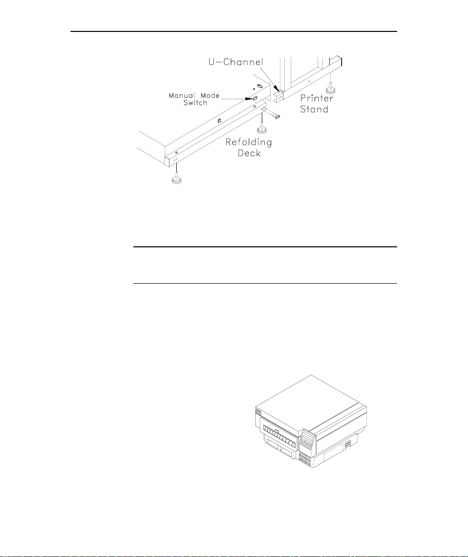
2. Position U-channels of printer stand rails just opposite
open rails of refolding deck, as shown in the next
illustration.
NOTE: It is possible to install the deck backwards. Make
sure you orient the deck, as shown in the illustration, so
that the corner of the deck with the manual mode switch is
located nearest the printer stand.
3. Insert channels of printer stand into rails of refolding deck
so that two pairs of screw holes line up. (It may be
necessary to temporarily loosen the four screws that
secure the refolding deck to its rails.)
4. Secure the two halves of the stacker with the screwdriver
and four, 3/8-in.-long Phillips screws provided in the
accessory box.
5. If necessary, retighten screws to resecure deck to its rails.
8 LaserMatrix Floor Model Stacker
LB0-D3
6. Tilt this assembly and screw in floor glides near the ends
and middle of the rails. Adjust the glides so that the
stacker is stable.
NOTE: An optional set of six casters can be used in place
of the floor glides.
7. Place the stacker in position and then place the printer on
the printer stand. Also, check to see that the front of the
printer is parallel to the front edge of the stand.
The feet on the printer must rest in the indentations
provided in the stand.
8. Do one of the
following:
• If you have a 24
page per minute
LaserMatrix printer,
proceed to Step 9.
• If you have a 16
paper per minute
PB0-A
24 Page Per Minute
LaserMatrix Printer
Other manuals for LaserMatrix Floor Model Stacker
1
This manual suits for next models
2
Table of contents
Other Output Technology Printer Accessories manuals


