Oval EL2310 Series User manual

Ins. No. E-022-4-E
1
SMART COMMUNICATION UNIT
MODEL EL 2310-05E □□□
Applicable flowmeter: OVAL Coriolis Flowmeters
ULTRA
mass MKⅡ
, Mass Flex, ST
mass MKⅡ
, VR
mass
Transmitters: CT9401, ST9801, EV9201
MT9411, MT9603, MT9431
For the installation of application software “LinkTop” and the interface
driver, refer to Ins. No. E-020IMB “Smart Communication Unit MODEL:
EL2310 Software Installation Procedure Manual”.

E-022-4-E
2
CONTENTS
1. SMART COMMUNICATION UNIT......................................................................................... 4
1.1 General .................................................................................................................................... 4
2. BEFORE YOU BEGIN ............................................................................................................. 5
2.1 Inspection upon Receipt ..........................................................................................................5
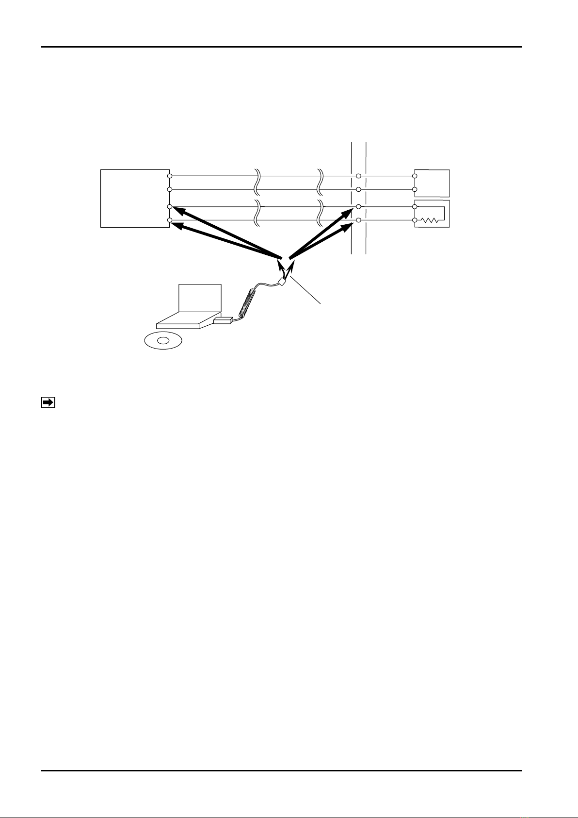
2.2 Hookup with Associated Equipment and Devices ................................................................... 6
2.3 PC Interface Adapter ............................................................................................................... 7
3. EL2310 OPERATION ............................................................................................................... 8
3.1 LinkTop Screen ........................................................................................................................ 8
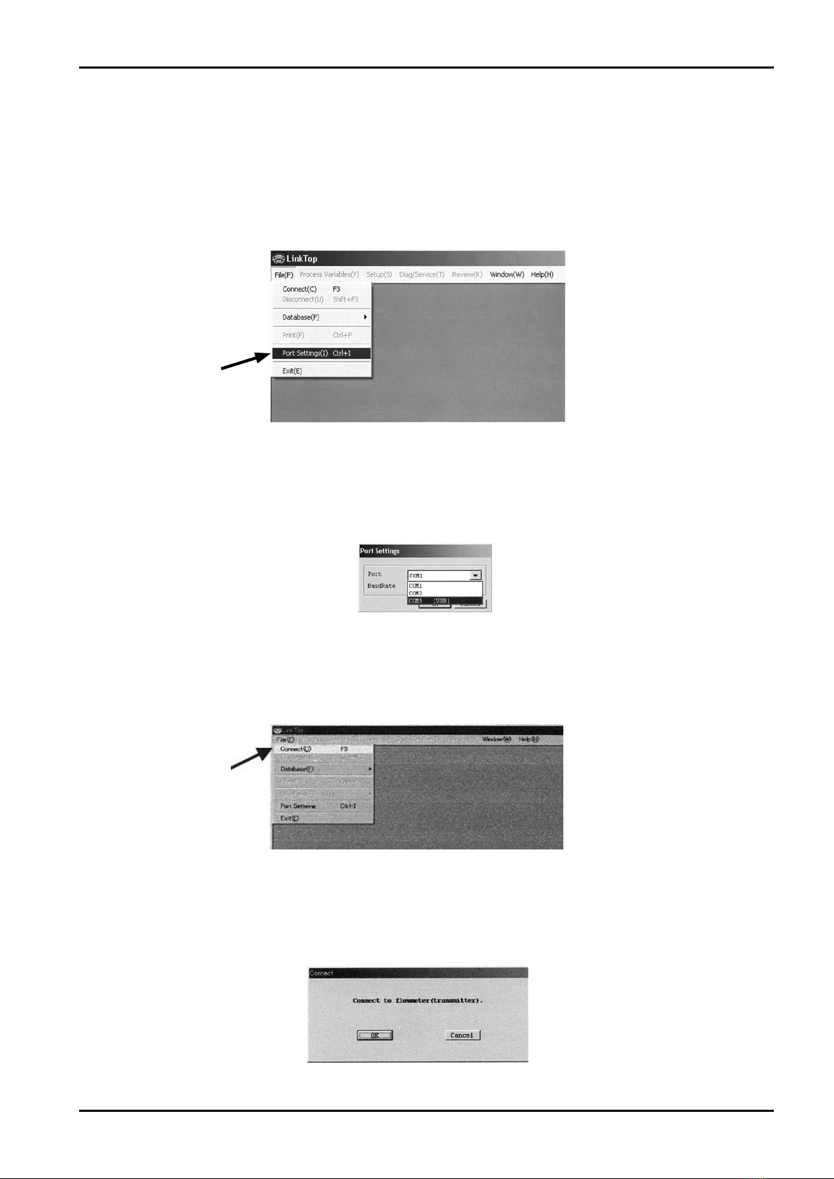
3.2 Starting the LinkTop and Connecions...................................................................................... 9
3.3 Terminating the Connection................................................................................................... 11
3.4 Terminating the LinkTop......................................................................................................... 12
3.5 Menu : Process Variables...................................................................................................... 13
3.5.1 Measure Process Variables (View Fld Dev Vars) ............................................................ 13
3.5.2 H/L Alarm (View H/L alarm)............................................................................................. 14
3.5.3 Measure Total Flow (Totalizer cntl).................................................................................. 14
3.6 Menu : Setup ......................................................................................................................... 15
3.6.1 Assign .............................................................................................................................. 15
3.6.2 Transmitter Parameters (Config fld dev var) .................................................................... 17
3.6.3 Analog output 1 ............................................................................................................... 19
3.6.4 Analog output 2 ............................................................................................................... 20
3.6.5 Pulse output..................................................................................................................... 20
3.6.6 Status input...................................................................................................................... 21
3.6.7 Status output....................................................................................................................22
3.6.8 H/L alarm......................................................................................................................... 24
3.6.9 Error Output Select (Error select) .................................................................................... 26
3.6.10 Output Level in an Error (Error indicator) ....................................................................... 28
3.6.11 Burst Mode Setup (HART output)................................................................................... 29
3.6.12 Bore size ........................................................................................................................ 30
3.6.13 Flow Calibration Factor (Flow Cal) ................................................................................. 31
3.6.14 Density Factor (Density Cal) .......................................................................................... 32
3.6.15 Zero Factor..................................................................................................................... 33
3.6.16 Transmitter Information (Device Information) ................................................................. 34
3.7 Menu : Diag/Service .............................................................................................................. 36
3.7.1 Transmitter Diagnostics (Self test)....................................................................................36
3.7.2 Diagnostics of Transmitter LCD Display (LCD test).......................................................... 38
3.7.3 Loop Test of Analog Output 1 (Fix Analog 1) ................................................................... 39
3.7.4 Loop Test of Analog Output 2 (Fix Analog 2) ................................................................... 40
3.7.5 Loop Test of Pulse Output (Fix Pulse).............................................................................. 41
3.7.6 Loop Test of Status Output (Fix Status output) ................................................................ 42
3.7.7 Loop Test of Status Input (Status input) ...........................................................................43
3.7.8 Key protect....................................................................................................................... 44
3.7.9 Zero Point Adjustment (Auto Zero)................................................................................... 45
3.7.10 Density Calibration (Density cal) .................................................................................... 47

E-022-4-E
3
3.7.11 Trim Analog Output 1 (Trim Analog 1)............................................................................. 49
3.7.12 Trim Analog Output 2 (Trim Analog 2) ............................................................................ 52
3.8 Menu : Review (a list of setup parameters)............................................................................ 52
3.8.1 Transmitter Status (Xmtr status) ...................................................................................... 52
3.8.2 Transmitter Information (Device info)............................................................................... 53
3.8.3 Flow Calibration Factor (Charize sensor).........................................................................53
3.8.4 View Transmitter Variables (Fld dev vars) .......................................................................54
3.8.5 View Outputs ................................................................................................................... 54
3.9 Menu : Window...................................................................................................................... 55
3.10 Database.............................................................................................................................. 56
3.10.1 Open file......................................................................................................................... 56
3.10.2 Save file ......................................................................................................................... 57
3.10.3 Delete file ....................................................................................................................... 58
3.10.4 Download ....................................................................................................................... 59
3.11 Printing ................................................................................................................................. 61
3.12 If There is No Rsponse ........................................................................................................ 63
3.13 If Connecting the Flowmeter Fails........................................................................................ 63
3.14 Input Errors ..........................................................................................................................64
3.15 Error Messages.................................................................................................................... 65
3.16 Parameters........................................................................................................................... 66
4. PRODUCT CODE EXPLANATION ..................................................................................... 69
5. GENERAL SPECIFICATIONS ............................................................................................. 70
CONVENTIONS
Shown in this manual are the signal words NOTE, CAUTION and
WARNING, as described in the examples below:
NOTE: Notes are separated from the general text to bring
the user's attention to important information.
CAUTION: Caution statements signal the user about hazards or
unsafe practices which could result in minor personal
injury or product or property damage.
WARNING: Warning statements signal the user about hazards
or unsafe practices which could result in severe
personal injury or death.

E-022-4-E
4
1. SMART COMMUNICATION UNIT
1.1 General
Described in this manual are the operating instructions to use the Smart Communication Unit Model
EL2310 which operates in the Microsoft operating system Windows environment.
The EL2310 is a communication terminal designed for use in combination with a personal computer
(hereinafter referred to as PC) and any one of the OVAL Coriolis series flowmeters to set up, alter,
adjust, or read out parameters and variables, through interactive communications, locally at the point of
measurement or from a terminal in a remote location. Using a Windows PC at hand, you can monitor
multiple windows on its screen.
※1.TheEL2310operatesontheapplicationsoftware"LinkTop"furnished.
※2.ThisinstructionmanualappliestothetransmitterST9801(MT9603)for the STmass MKⅡ,
transmitter CT9401 (MT9411) for the ULTRAmas MKⅡ(including the Mass Flex), transmitter EV9201
for the VRmass,"D"sensorandextra-highpressureservicetransmitterMT9431
The application software automatically distinguishes between the transmitter connected and
changes the window accordingly from the STmass MKⅡto the VRmass, and vice versa.
Since they basically have windows in common, the windows covered in this manual are of the
ULTRAmass MKⅡ.

LinkTop for Coriolis3
Applicable for
CT9401
ST9801
EV9201
MT9411
MT9431
MT9603
®
E-022-4-E
5
CD-ROM(one)
(LinkTop and driver)
Interface Adapter
Fig.1
2. BEFORE YOU BEGIN
2.1 Inspection Upon Receipt
※Be sure you have the following items.
Remove the products from the EL2310 carton and make sure you have all the components required.
NOTE: For the installation of “LinkTop” and the interface driver, refer to “Installation Procedure
Manual”.

Flowmeter
Transmitter
OVAL Coriolis Flowmeter Receiving Instrument
(Load RLbuilt in)
Connection
Points
PC
Interface
Application Software
(LinkTop)
Probe
Polarity observation not required.
Connect probe acrosss + and - terminals
of analog output.
Tie-point
Terminal Block
LINE/+
NEUT/−
LINE/+Power
RL
NEUT/−
+4〜20mADC
−
+
−
E-022-4-E
6
Fig.2
2.2 Hookup with Associated Equipment and Devices
Equipmentset-upwithassociatedequipmentanddevicesareshowninFig.2.
NOTE: In Fig. 2, the customer is to supply the PC that meets the following requirements:
◇PC/AT compatible (DOS/V machine)
◇Operating system is the Windows 2000, Windows XP, Windows Vista, Windows 7 to 10.
◇RAM: 8MB or larger.
◇Hard disk: 10MB or larger
◇Provision of USB port
Thereceivinginstrumentinthefigureaboverequiresaloadresistance250Ωmin.Itsupperlimitdepends
on the specification of transmitter used.
Ifthereceivinginstrumentdoesnothaveabuilt-inRL, use it with an external RLconnected in series.

USB connector
Body
Cable length from
probe 500 approx.
Cable length from
connector 1000 approx.
50
Probe
(60)
E-022-4-E
7
Fig.3
2.3 PC Interface Adapter
Comprised of components as shown in Fig. 3, it converts the flowmeter transmitter signal (Bell 202) into
the USB signal.
All dimension in millimeters

E-022-4-E
8
3.EL2310 OPERATION
3.1 About LinkTop Screen
Fig. 4 shows how the LinkTop window looks like.
Fig.4
Menu
PC-to-Flowmeter
Communications Status
Title Bar
Message Box Field
The state of communications is indicated at bottom left of the screen by :
◇During communications : RX WAIT
◇Communications interrupted : IDLE

E-022-4-E
9
Fig.5
Click here.
Fig.6
Fig.7
Click here..
Fig.8
3.2 Starting the LinkTop and Connections
①Hookuptheowmetertransmitter,PCinterfaceadapter,and"LinkTop"preinstalledPCasshownin
Fig. 2.
②TogettheLinkTopupandrunning,clickfrom"Start"atlowerleftofthePCscreenandclick"LinkTop
forCoriolis3(J)"from"Program".
③Click"Portsetting(I)Ctrl+I"in"File(F)"atthetop-levelmenuofscreen.
④Set up the port.
Select the option labeled COM □(USB)andclick"OK"( □is the port number connected to the interface).
⑤OnseetingthescreenliketheoneshowninFig.7,click"Connect(C)F3"in"File(F)"atthetop-level
menu of screen.
⑥AtthemessageboxasliketheoneinFig.8,click"OK"buttonandtheconnectionprocessbegins.

E-022-4-E
10
Fig.9
Fig.10
Fig.11
⑦Asyouclick"OK"andstarttheconnectionprocess,amessageboxliketheoneinFig.9appears.
A bar graph in the middle of message box indicates progress of connection process.
When the connection process begins, the transmitter connected is automatically identified and the
transmitternameappearsinthetitlebar.Amessageindicating"ongoingcommunication"appearsat
lowerleftofthescreenwith"IDLE" ⇔"RXWAIT"shownalternately.
⑧Uponcompletionofconnections,amessageboxliketheoneinFig.10appears.Click"OK"button.
⑨Whenconnectioniscomplete,ofthemenusatthetop-levelmenuofscreen,certainitemsthathad
been dimmed and couldn't be chosen are usable now (menu characters turned black).

E-022-4-E
11
Fig.12
Click here.
Fig.13
Fig.14
3.3 Terminating the Connection
ToterminateconnectionbetweentheowmetertransmitterandLinkTop,followtheproceduregivenbelow:
①Clickon"File(F)"attop-levelmenuonthescreenasshowninFig.12,select"Disconnect(U)Shift+F3"
and click on again.
②AtthemessageboxasshowninFig.13,clickon"OK."Thisbringstheconnectionbetweentheowmeter
and LinkTop to come to an end.
③Clickingon"Cancel"abandonstheprocessofterminatingtheconnection.
④When connection is terminated, part of the menu turns to be inactive (characters turn to white in color)
as shown in Fig. 14.

E-022-4-E
12
Fig.15
3.4 Terminating the LinkTop
ToexittheLinkTop,clickon"File(F)"attop-levelmenuofthescreen,select"Exit(E),"andclickonagain.
AmessageboxasshowninFig.15appears.IfyouaresuretoexittheLinkTop,clickon"OK"button.
Clickingon"OK"buttonwillcausetheapplicationwindowtodisappearfromthedesktop.
Toaborttheterminatingprocess,clickon"Cancel."

E-022-4-E
13
Fig.16
Fig.17
Click here.
3.5 Menu : Process Variables
At"ProcessVariables,"theprocessvariablesoftheflowmeter(instantaneousflowrate,fluiddensity,
uidtemperature,totalow,analogoutput),andH/Lalarmcanbereviewed.Youcanalsoresetthetotal
counter.
3.5.1 Measure Process Variables (View Fld Dev Vars)
①Clickon"ProcessVariable(V)"atthetop-levelmenuofthescreenandclickon"Viewdevavers"again.
②A message box for measuring process variables appears as shown in Fig. 17.
InST9801,thereisno"VolumeFlow"menu.
InEV9201,neither"VolumeFlow"nor"Dens"menuisshown.
③Ifanyproblemisfoundintheowmetertransmitter,anerrormessageappearsinawindowbelowthe
messageboxforprocessvariables.Fordetailedinformation,see"3.15ErrorMessages".
Forthetotalcounterdisplay,see"3.MeasureTotalFlow(Totalizercntl)".
④Tohidethemessageboxforprocessvariables,clickon"Cancel".

E-022-4-E
14
Fig.18
3.5.2 H/L Alarm (View H/L alarm)
①Clickon"ProcessVariables(V)"attop-levelmenu,select"ViewH/Lalarm",andclickonagain.
A message box for H/L alarm then appears as shown in Fig. 18.
②AtViewH/Lalarm,the"H/Lalarmstatus"changesfrom"NoTriggered"to"Triggered"whentheselected
itemat"H/Lalarmvars"of"Statusoutput"reaches"Highalarmpoint"or"Lowalarmpoint,"andthe
Statusoutputchangesfrom"ON"to"OFF."
Inthisconnection,"H/Lalarmstatus"isvalidonlywhen"H/LAlarm"isselectedat"Statusoutputfunc".
Aslongasyouroptionisotherthan"H/LAlarm,"the"H/Lalarmstatus"doesnotchangeto"Triggered"
whetherornotthesetpointisexceeded,andthestatusoutputalsoremainsunchangedat"ON."
③TohidetheH/Lalarmmessagebox,clickon"Cancel."
3.5.3 Measure Total Flow (Totalizer cntl)
①Clickon"ProcessVariable(V)"attop-levelmenuonthescreen,select"Totalizercntl", and click on
again.Amessageboxformeasuringthetotalowappearsasshownin Fig. 19.
Fig.19
②Totalowcomesin"F-Total","R-Total"and"Diff-Total".
・"F-Total":Countsupwhiletheuidowsinthedirection(forward)setat"Flowdirection."
・"R-Total":Countsupwhiletheuidowsinthereversedirectionwith"BiDirection"selectedat"Status
outputfunc".
・Diff-Total": Meansarelationship"Diff-Total=F-Total−R-Total"andisequalto"F-Total"except"Bidirection"
is selected.
Here,theowdirectionindicatedontheowmeterisregardedas"forwarddirection"when"Flowdirection"
is"Forward". Theowdirectionoppositetothearrowdirectionindicatedontheowmeterisregardedas
"forwarddirection"whenitis"Reverse".
③Atthismessagebox,youcan"Start","Stop"or"Reset"thetotalcounter.Rememberthat"Start",
"Stop"and"Reset"arevalidforthetotalcounterreading,andbynomeansaffectthepulseoutput.
④Tohidethemessageboxfortotalowmeasurement,clickon"Cancel."

E-022-4-E
15
Click here.
Fig.20
Fig.21
3.6 Menu : Setup
At"Setup",youcansetupowmeterparameters,transmitterinformation,etc.
CAUTION
To prevent erratic operation attributable to improper, conflicting parameter
settings, make sure, following changes in parameters, that the changes in
settings have correctly been made by comparing against "Menu : Review (a list
of setup parameters)".
If"Dia/Service(T)"messageboxisshownonthescreen,youcannotsetupparameters,transmitter
information, etc. Close that message box (Epsom) before you begin.
3.6.1 Assign
①Clickon"Setup(S)"attop-levelmenuofthescreen,select"Assign", and click on again.
②A message box as shown in Fig. 21 appears. At this window, Analog outputs 1 and 2, and Pulse output
are assigned.
SincethepulseoutputofST9801andEV9201isfixedto"MassFlow", item"Pulseoutput"isnot
available.

E-022-4-E
16
Fig.23
Fig.24
Fig.22
③Assignindividualitems:clickonthearrowmartatrightoftheeldandselectyouroptionfromthe
drop-downlistasshowninFig.22.
At"Analogoutput1"and"Analogoutput2",anitem"VolumeFlow"isnotavailable.
In"Analogoutput1"and"Analogoutput2",neither"VolumeFlow"nor"Density"menuitemisshown.
④Afterllinginalltheeldsrequired,clickon"OK"button.AmessageboxasshowninFig.23then
appears.
Clickingon"OK"atthispointchangestheprevioussettingstothenewsettingsjustentered.However,
theowmeteroutputalsochangeswiththechangesinsettingsmade.Forsafety'ssake,therefore,
inapplicationswheretheowmeteroutputcontrolsavalve(s)orotherdevices,itisnecessarythatthe
controlloopbeswitchedtomanualcontroltoensurethatthecontrolloopisunaffectedbytheowmeter
output.
⑤When the previous settings are replaced with the new settings just entered in response to clicking on
"OK",amassageboxasshowninFig.24appears.Clickingon"OK"buttonatthispointcompletesthe
setup.
⑥Afterclickingon"OK"button,themessageboxforllingineldsofmenuitemsappearsagain.
Clickon"Cancel"buttontohidethesetupmessagebox.
Toabortthesetupprocess,clickon"Cancel"buttoninthecourseofsteps②through ④.

E-022-4-E
17
Fig.25
3.6.2 Transmitter Parameters (Config fld dev var)
①Clickon"Setup(S)"atthetop-levelmenuofthescreen,select"Congddevvar"drop-downmenu,
and click again.
②AmessageboxliketheoneshowninFig.25appears.Transmitterparameters(owrate,density,and
temperature related parameters) are set up at this window.
③At the Flow menu, you can set up mass flowrate unit, volume flowrate unit, flow direction, flow
damping, and flow cutoff.
IntheST9801andEV9201,thereisno"Volumeflowunit"menuitem.
Flow direction is either "Forward" of "Reverse." In the "Forward", the flow direction indicated by the
arrow on the flowmeter body is taken as "Forward", whereas in the "Reverse", the flow direction
oppositetothearrowistakenas"Forward".
"Flow cutoff" reads in percent with respect to the max. permissible flowrate and functions both in
forwardandreverseflow.Defaultsettingis"0.3%".
④At the Density menu, you can set up density unit, density damping, slug flow identification, and density
correction.
In slug flow identification, any flow in which the obtained density measurement exceeds preselected
"Sluglowlimit"or"Slughighlimit"isinterpretedasagas-mixedfloworslugflow,andtheobtained
flowmeterresultsandtheiroutputsareforciblyreducedto"0."Whensettingsaresuchthat"Sluglow
limit"=0and"Slughighlimit"=10,theslugflowidentifyingfunctionisinactivated.However,within
theperiodpresetat"Slugduration", the transmitter ignores the status of a slug flow and continues
usual measurement.
In density correction, density and volume flow readings are reduced to the values corrected at the
referencetemperatureif"Compensation"is"ON"(conversioncalculatedonthebasisof"Standard
temp"and"ExpansionCoef").
IntheEV9201,thereisno"Density"menuitem.
⑤At"Temp", you can set up temperature units and temperature damping.
⑥Youaretosetupindividualitems:foritemswithanarrowmarkatright,clickonthearrowmarkat
right,selecttheitemfromthedrop-downlist;forotheritems,Keyinappropriatevaluesdirectly.

E-022-4-E
18
⑦Afterllinginalltheeldsrequired,clickon"OK"button.AmessageboxasshowninFig.26then
appears.
Clickingon"OK"atthiswindowchangestheprevioussettingstothenewsettingsjustentered.
However,theowmeteroutputalsochangeswiththechangesinsettingsmade.Forsafety'ssake,
therefore, in applications where the flowmeter output controls a valve or other devices, it is
necessary that the control loop be switched to manual control to ensure that the control loop is
unaffectedbytheowmeteroutput.
⑧When the previous settings are replaced with the new settings just entered in response to clicking on
"OK",amessageboxasshowninFig.27appears.Clickingon"OK"buttonatthispointcompletes
the setup.
Fig.26
Fig.27
⑨Afterclickingon"OK"button,themessageboxforllingineldsofmenuitemsappearsagain.
Clickon"Cancel"buttontohidethemessageboxforllingineldsofsetupitems.
Toabortthesetupprocess,clickon"Cancel"buttoninthecourseofsteps②through ⑦.
CAUTION
When the units of measurement are changed, it is necessary to change the units of
measurement included in other message boxes. When Some message box is open with
units of measurement included, close that message box once and then open it again
before renewing the units.

E-022-4-E
19
Fig.28
Fig.29
Fig.30
3.6.3 Analog output 1
①Clickon"Setup(S)"atthetop-levelmenuofthescreen,select"AnalogOutput1"from"Congoutput"
drop-downmenu,andclickonagain.
②A message box like the one shown in Fig. 28 appears. Analog output 1 is set up at this window.
③ You are to set up individual items. Acceptable ranges of USL (sensor's upper limit), LSL (sensor's
lower limit), Min. Span are shown at URV (setting at 20mA) and LRV (setting at 4mA) as a guide to
your entering setpoints.
Thelowcutofffunctionis"OFF"whenyour"Lowcut"optionis"0.0%".Defaultis"0.0%". When items
other than flowrate (mass and volume) are assigned, do not fail to set to "0.0%". If "Bi direction" is
chosen, the low cutoff functions both in the forward and reverse directions.
④Afterfilling in allthefields required,clickon "OK" button.AmessageboxasshowninFig.29 then
appears.
Clickingon"OK"atthiswindowchangestheprevioussettingstothenewsettingsjustentered.
However, the flowmeter output also changes with the changes in settings made. For safety's
sake, therefore, in applications where the flowmeter output controls a valve (s) or other devices, it
is necessary that the control loop be switched to manual control to ensure that the control loop is
unaffected by the flowmeter output.
⑤When the previous settings are replaced with the new settings just entered in response to clicking on
"OK",amessageboxasshowninFig.30appears.Clickingon"OK"buttonatthispointcompletesthe
setup.
⑥Clickingon"OK"bringsthescreentoreturntothemessageboxforllingineldsofitems.
Clickon"Cancel"buttontohidethemessageboxforllingineldsofitems.
Toabortthesetupprocess,clickon"Cancel"buttoninthecourseofsteps②through ④.

E-022-4-E
20
Fig.31
Fig.32
Fig.33
3.6.4 Analog Output 2
①Clickon"Setup(S)"atthetop-levelmenuofthescreen,select"AnalogOutput2"from"Congoutput"
drop-downmenu,andclickonagain.
②Similar to the procedure outlined in Steps ②through ⑤in"3.AnalogOutput1", Analog output 2 is set
up here.
3.6.5 Pulse Output
①Clickon"Setup(S)"atthetop-levelmenuofthescreen,select"Pulseoutput"from"Congoutput"
drop-downmenu,andclickonagain.
②A message box like the one shown in Fig. 31 appears. Pulse output 2 is set up at this window.
③Youaretosetupindividualitems.
Thelowcutoffis"OFF"whenyour"Lowcut"optionis"0.0%".Defaultsettingis"0.0%".
If"Bidirection"ischosen,thecutofffunctionsbothintheforwardandreversedirection.
④Afterllinginalltheeldsrequired,clickon"OK"button.AmessageboxasshowninFig.32then
appears.
Clickingon"OK"atthiswindowchangestheprevioussettingstothenewsettingsjustentered.
However,theowmeteroutputalsochangeswiththechangesinsettingsmade.Forsafety'ssake,
therefore,inapplicationswheretheowmeteroutputcontrolsavalveorotherdevices,itisnecessary
that the control loop be switched to manual control to ensure that the control loop is unaffected by the
owmeteroutput.
⑤When the previous settings are replaced with the new settings just entered in response to clicking on
"OK",amessageboxasshowninFig.33appears.Clickingon"OK"buttonatthispointcompletesthe
setup.
⑥Afterclickingon"OK"button,themessageboxforfillinginfieldsofitemsappearsagain.Clickon
"Cancel"buttontohidethemessageboxforllingineldsofitems.Toabortthesetupprocess,click
on"Cancel"buttoninthecourseofsteps ②through ④.
This manual suits for next models
1
Table of contents
Other Oval Cell Phone manuals