4. INSTALLATION
Installation Location
Select an installation location where
1. Mechanical vibration, shock and corrosive gases
least exist.
2. Air is dry and temperature is near to ambient and
stable.
NOTE : Although the max. allowable temp. is
+50°C, use in place its temp. possibly
near to ambient is recommended.
3. Potential sources of inductive interference, such as
electromagnetic contactors, are located sufficiently
away.
4. A lightening arrestor is provided if incoming signals
aresubjecttopotentialinuenceoflightening.
5. A sufficient working space is secured behind the
instrument to facilitate wiring and maintenance.
5. WIRING
1. Separate field wiring from other power lines or
powercircuitstominimizethepossibilityofinductive
interference.
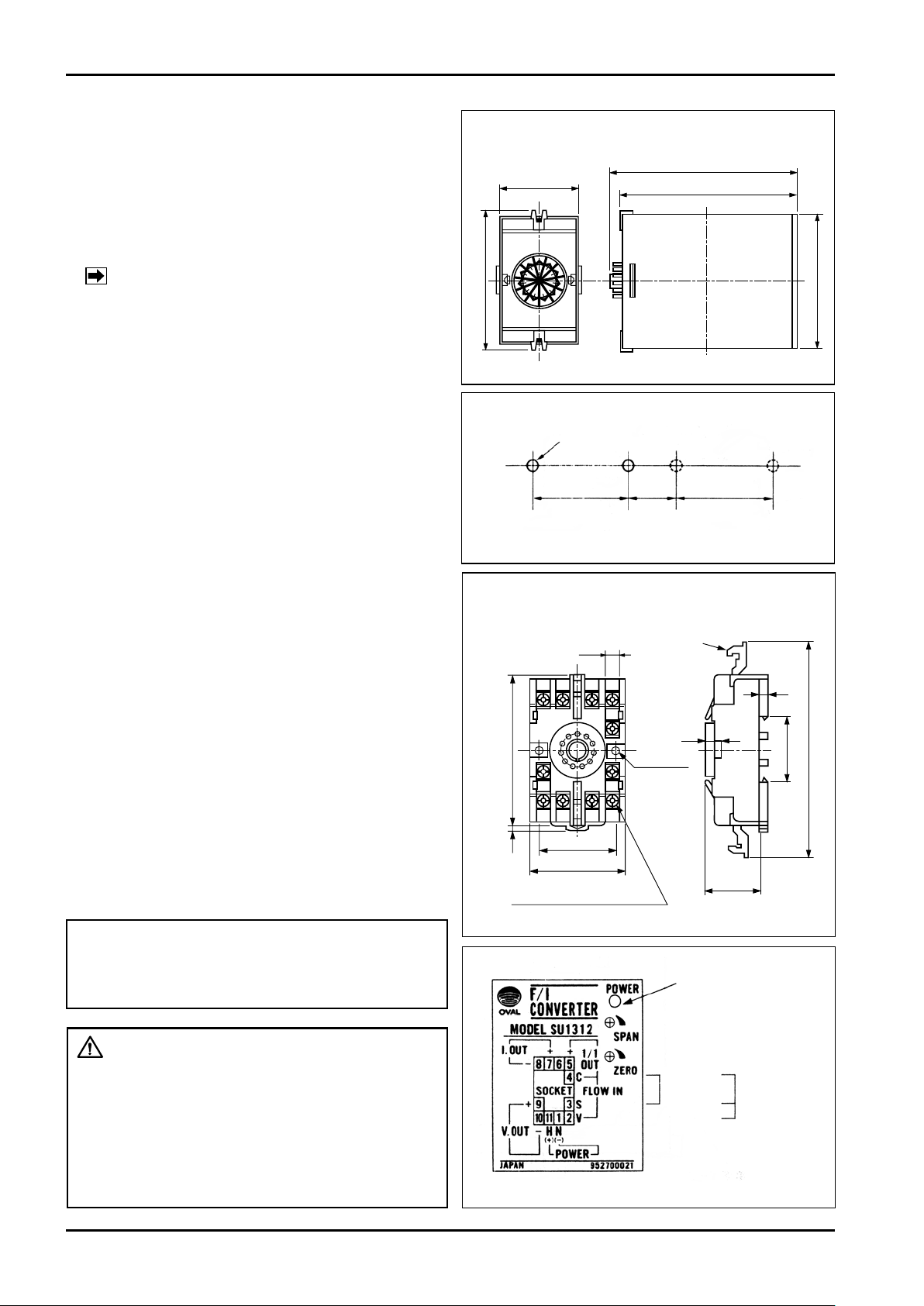
2. Terminal arrangement is shown in Fig. 5.
3. M3.5 x 7 screws are used for terminals. Ensure good
electrical connections.
4. Upon completion of wiring connections, install the
converter body into the socket. Then engage the
locking levers on the socket assembly with the
converter body.
5. For signal cables, electrostatically-shielded,
polyethyleneinsulated, vinyl-sheathed control cables
(CEVS1.25to2.00mm2,2-or3-conductor),or
equivalent, must be used. With a conductor area
2mm2, the maximum transmission length is typically
one kilometer.
2− φ4.5
7.8
35.4
118max.
4
4
5
33.5max.
81max.
4
40±0.2
51max.
TERMINAL
SCREW : 11−M3.5×7
LOCK LEVER
211110
3
4
5678
9
• OUTLINE DIMENSIONS,
SURFACE CONNECTION SOCKET ASSEMBLY
(11PFA)
Fig. 4
• CONNECTION TERMINALS
Fig. 5
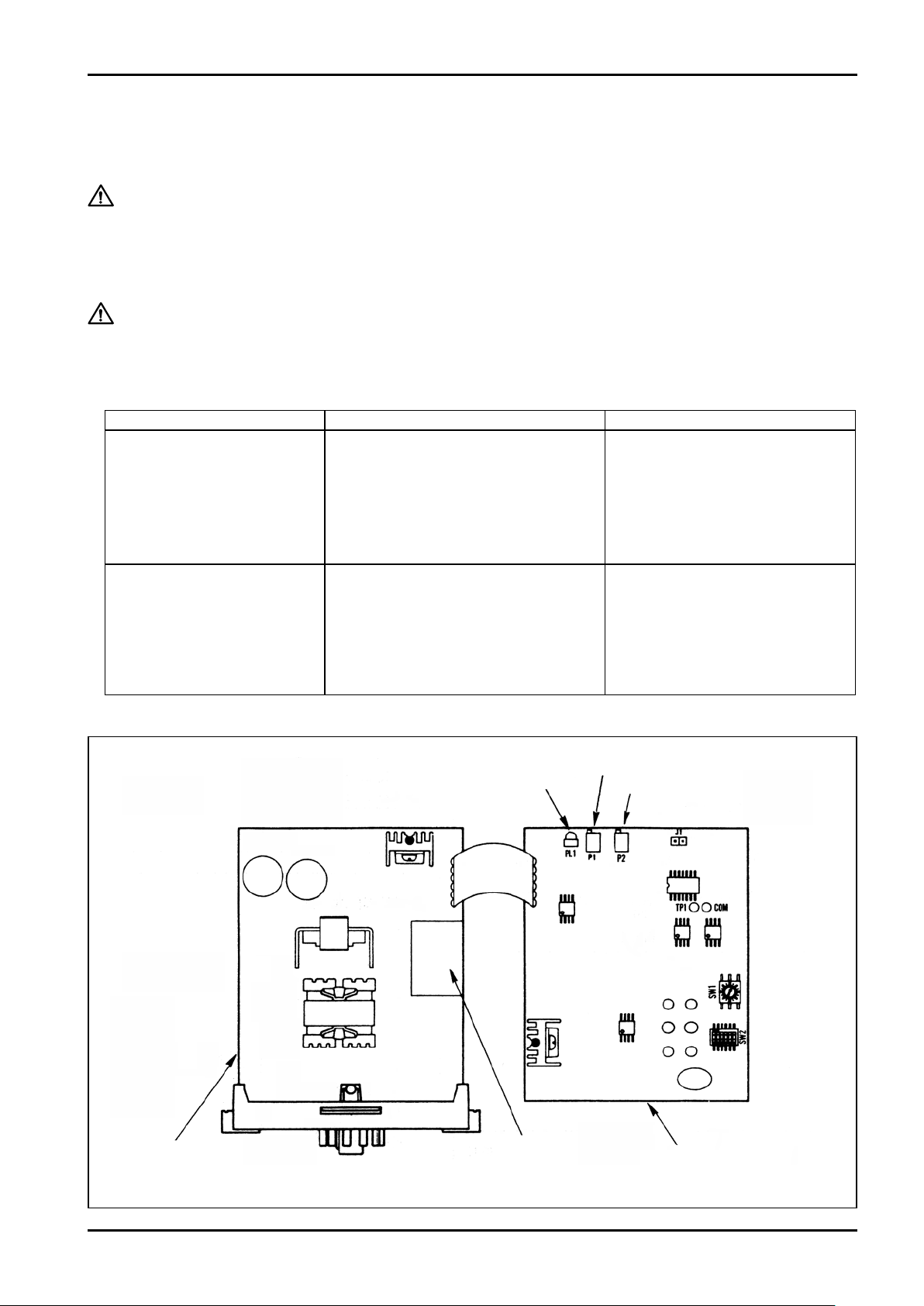
POWER INDICATIOR
2-WIRE
INPUT 3-WIRE
INPUT
COM.
SIG.
SUP.
−
+
• OUTLINE DIMENSIONS, CONVERTER BODY
Fig. 2
• MOUNTING CENTERS
Fig. 3
2−M4FITTINGHOLE
40±0.2 40±0.2min.
20
IMPORTANT :
Make electrical connections upon confirmation of
validity of flowmeter (pulse generator) and receiving
instrument combination by their model No., serial No.,
etc.
CAUTION:
Notes on Wiring
- When I. OUT is not used, make a connection
between terminals (7) and (8). If L OUT is open, V.
OUT is not generated.
- When V. OUT is not used, make a connection
between terminals (9) and (10), then a
connection of load resistance up to 600Ωis
permitted for I. OUT.