oventrop 1344697 User manual

Premium Armaturen + Systeme
Betriebsanleitung
DE Aufputzschrank
für die Wohnungsstation „Regudis W-HTE“
Operating instructions
EN Surface-mounted cabinet
for dwelling station “Regudis W-HTE”
Notice d’utilisation
FR Coffret pour pose en applique
pour station d’appartement «Regudis W-HTE»


Aufputzschrank Inhaltsverzeichnis
3
134469780-V03.04.2019
1. Allgemeine Angaben ...............................................................................................................5
1.1 Gültigkeit der Anleitung.............................................................................................................5
1.2 Lieferumfang .............................................................................................................................5
1.3 Kontakt......................................................................................................................................5
1.4 Urheber- und Schutzrechte.......................................................................................................5
1.5 Verwendete Symbole ................................................................................................................5
2. Sicherheitsbezogene Informationen .....................................................................................5
2.1 Normative Vorgaben..................................................................................................................5
2.2 Bestimmungsgemäße Verwendung ..........................................................................................5
2.3 Änderungen am Produkt ...........................................................................................................5
2.4 Warnhinweise ............................................................................................................................6
2.5 Sicherheitshinweise...................................................................................................................6
2.5.1 Verletzungsgefahr durch hohes Eigengewicht.........................................................................................6
2.5.2 Verletzungsgefahr bei unsachgemäßer Arbeit .........................................................................................6
2.5.3 Verfügbarkeit der Betriebsanleitung......................................................................................................... 6
3. Technische Beschreibung ......................................................................................................7
3.1 Aufbau.......................................................................................................................................7
3.2 Maße .........................................................................................................................................8
3.3 Technische Daten......................................................................................................................8
4. Zubehör und Ersatzteile .........................................................................................................9
5. Transport und Lagerung .........................................................................................................9
6. Montage .................................................................................................................................10
6.1 Montage ..................................................................................................................................10
6.2 Schutzpotentialausgleich/Erdung ...........................................................................................10
7. Demontage und Entsorgung ................................................................................................11
Inhalt
Seite


Aufputzschrank Allgemeine Angaben
5
134469780-V03.04.2019
1. Allgemeine Angaben
Die Originalbetriebsanleitung ist in deutscher Spra-
che verfasst.
Die Betriebsanleitungen anderer Sprachen wurden
aus dem Deutschen übersetzt.
1.1 Gültigkeit der Anleitung
Diese Anleitung gilt für die Aufputzschränke mit der
Artikelnummer 1344697, 1344698 und 1344699.
1.2 Lieferumfang
Prüfen Sie Ihre Lieferung auf Transportschäden und
Vollständigkeit.
Der Lieferumfang umfasst
• Aufputzschrank für „Regudis W-HTE“
• Befestigungsmaterial für Verteiler (bei Artikelnum-
mer 1344698 und 1344699)
• Befestigungsmaterial für Wohnungsstation
• Zubehör für Potentialausgleich
1.3 Kontakt
Kontaktadresse
OVENTROP GmbH & Co. KG
Paul-Oventrop-Straße 1
59939 Olsberg
Deutschland
Technischer Kundendienst
Telefon: +49 (0) 29 62 82-234
1.4 Urheber- und Schutzrechte
Diese Anleitung ist urheberrechtlich geschützt. Sie ist
ausschließlich für die mit dem Produkt beschäftigten
Personen bestimmt.
1.5 Verwendete Symbole
Kennzeichnet wichtige Informationen und wei-
terführende Ergänzungen.
fHandlungsaufforderung
• Aufzählung
1.
2.
Feste Reihenfolge. Handlungsschritte 1 bis X.
ZErgebnis der Handlung
2. Sicherheitsbezogene
Informationen
2.1 Normative Vorgaben
Beachten Sie die am Installationsort geltenden recht-
lichen Rahmenbedingungen.
Es gelten die aktuell gültigen Normen, Regeln und
Richtlinien.
2.2 Bestimmungsgemäße Verwendung
Die Betriebssicherheit ist nur bei bestimmungsgemä-
ßer Verwendung des Produktes gewährleistet.
Der Aufputzschrank dient zum direkten Einbau und
Schutz der Wohnungsstation „Regudis W-HTE“ und
ihrem Zubehör.
Jede darüber hinausgehende und/oder andersartige
Verwendung gilt als nicht bestimmungsgemäß.
Ansprüche jeglicher Art gegen den Hersteller und/
oder seine Bevollmächtigten wegen Schäden aus
nicht bestimmungsgemäßer Verwendung können
nicht anerkannt werden.
Zur bestimmungsgemäßen Verwendung zählt auch
die korrekte Einhaltung dieser Anleitung.
2.3 Änderungen am Produkt
Änderungen am Produkt sind untersagt. Bei Än-
derungen am Produkt erlischt die Produktgarantie.
Für Schäden und Betriebsstörungen, die sich aus
Änderungen am Produkt ergeben, haftet der Herstel-
ler nicht.

Sicherheitsbezogene Informationen Aufputzschrank
6134469780-V03.04.2019
2.4 Warnhinweise
Jeder Warnhinweis enthält folgende Elemente:
Warnsymbol
SIGNALWORT
Art und Quelle der Gefahr!
Mögliche Folgen, wenn die Gefahr eintritt
bzw. der Warnhinweis ignoriert wird.
fMöglichkeiten zur Vermeidung der Gefahr.
SignalwortedenierendieSchwerederGefahr,die
von einer Situation ausgeht.
GEFAHR
Kennzeichnet eine unmittelbare drohende
Gefahr mit hohem Risiko. Wenn die Situation
nicht vermieden wird, sind Tod oder
schwerste Verletzung die Folge.
ACHTUNG
Kennzeichnet eine Situation, die möglicher-
weise Sachschäden zur Folge haben kann,
wenn sie nicht vermieden wird.
2.5 Sicherheitshinweise
Dieses Produkt ist so konstruiert, dass es dem ge-
botenen Sicherheitsstandard von Wissenschaft und
Technik entspricht und ist betriebssicher. Dennoch
können bei Montage und Betrieb Restgefahren für
Personen und Sachwerte entstehen.
2.5.1 Verletzungsgefahr durch hohes
Eigengewicht
fTragen Sie bei der Montage Sicherheitsschuhe.
fZiehen Sie für die Montage weitere Personen hinzu.
2.5.2 Verletzungsgefahr bei unsachgemäßer
Arbeit
Kantige Bauteile, Spitzen und Ecken am und im Pro-
dukt können Verletzungen verursachen.
fSorgen Sie vor Beginn der Arbeiten für ausreichen-
den Platz.
fGehen Sie mit offenen oder scharfkantigen Bauteilen
vorsichtig um.
fHalten Sie den Arbeitsbereich aufgeräumt und sau-
ber, um Unfallquellen zu vermeiden.
2.5.3 Verfügbarkeit der Betriebsanleitung
Jede Person, die mit diesem Produkt arbeitet, muss
diese Anleitung und alle mitgeltenden Anleitungen
(z. B. Anleitung des Zubehörs) gelesen haben und
anwenden.
Die Anleitung muss am Einsatzort des Produktes
verfügbar sein.
fGeben Sie diese Anleitungen und alle mitgeltenden
Anleitungen (z. B. Anleitung des Zubehörs) an den
Betreiber weiter.

Aufputzschrank Technische Beschreibung
7
134469780-V03.04.2019
3. Technische Beschreibung
3.1 Aufbau
2
34
3
2
1
1
1
Abb. 1: Aufbau Aufputzschrank 1344697
(1) Wandbefestigungspunkte
(2) Gewindebolzen für „Regudis W-HTE“
(3) Gewindebolzen für Kugelhahnanschlussleiste
(4) Ausziehbare Füße mit Höhenmarkierung zur
Einstellung der Fußbodenaufbauhöhen (100 -
180 mm)
3
1
6
7
5
4
2
2
2
2
2
Abb. 2: Aufbau Aufputzschrank 1344698 und
1344699
(1) Befestigungsmöglichkeit für elektrischen An-
schlussleiste
(2) Wandbefestigungspunkte
(3) Gewindebolzen für „Regudis W-HTE“
(4) Gewindebolzen für Kugelhahnanschlussleiste
(5) Befestigungsschiene für Verteiler
(6) Ausziehbare Füße mit Höhenmarkierung zur
Einstellung der Fußbodenaufbauhöhen (100 -
180 mm)
(7) Befestigungspunkte für eine Steckdose
3
2
1
Abb. 3: Aufbau Aufputzschrank geschlossen
(1) Tür
(2) Rahmen
(3) Estrichblende

Technische Beschreibung Aufputzschrank
8134469780-V03.04.2019
3.2 Maße
12
3
Abb. 4: Maße Aufputzschrank 1344697
Aufputzschrank 1344697
(1) 750 mm
(2) 160 mm
(3) 745 - 860 mm
12
3
Abb. 5: Maße Aufputzschrank 1344698 und 1344699
Aufputzschrank
1344698
Aufputzschrank
1344699
(1) 750 mm 880 mm
(2) 160 mm 160 mm
(3) 1326 - 1441 mm 1326 - 1441 mm
3.3 Technische Daten
Gewicht Art.-Nr. 1344697 14,0 kg
Art.-Nr. 1344698 27,0 kg
Art.-Nr. 1344699 29,5 kg
Material Stahlblech, verzinkt
Farbe Weiß RAL 9010, matt

Aufputzschrank Zubehör und Ersatzteile
9
134469780-V03.04.2019
4. Zubehör und Ersatzteile
Ersatzteile und Zubehör erhalten Sie im Fachhandel.
Folgende Artikel können als Zubehör bezogen wer-
den:
• Zylinderschloss mit Schlüssel (Artikelnummer
1401191)
Abb. 6: Zylinderschloss mit Schlüssel
5. Transport und Lagerung
Transportieren Sie das Produkt in der Originalverpa-
ckung.
Lagern Sie das Produkt unter folgenden Bedingun-
gen:
Temperaturbereich -20°C bis +60°C
Relative Luftfeuch-
tigkeit
max. 95%
Partikel Trocken und staubgeschützt
Mechanische Ein-
üsse
Geschützt vor mechanischer
Erschütterung
Strahlung Geschützt vor UV-Strahlung
und direkter Sonnenein-
strahlung
Chemische Einüsse Nicht zusammen mit Lö-
sungsmitteln, Chemikalien,
Säuren, Kraftstoffen u.ä.
lagern

Montage Aufputzschrank
10 134469780-V03.04.2019
6. Montage
6.1 Montage
1. Entfernen Sie die Tür des Aufputzschrankes.
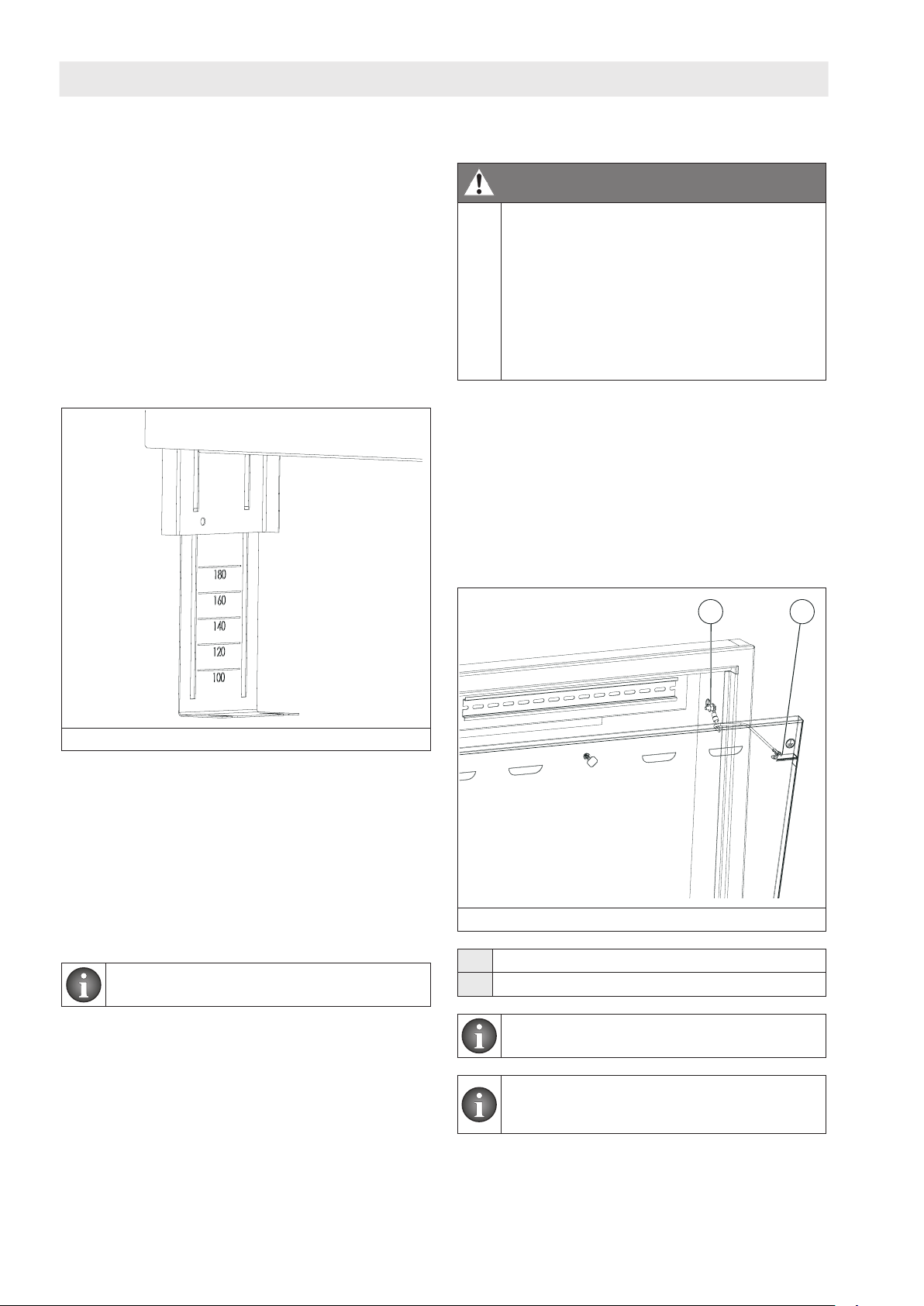
2. Stellen Sie die Füße des Aufputzschrankes auf die
gewünschte Höhe ein. Beachten Sie beim Einstellen
der Füße die Aufbauhöhe des Estrichs. Die Estri-
choberächesolltemind.1cmoberhalbderUn-
terkante der Estrichblende liegen. Beim Ausziehen
der Füße erscheint eine Höhenmarkierung (siehe
Abb. 7 auf Seite 10). Die angegebenen Maße sind
vom Boden bis zur Unterkante der Estrichblende.
Verstellenbzw.xierenSiedieFüße,indemSiedie
Flügelmuttern lösen bzw. anziehen.
Abb. 7: Höhenmarkierung
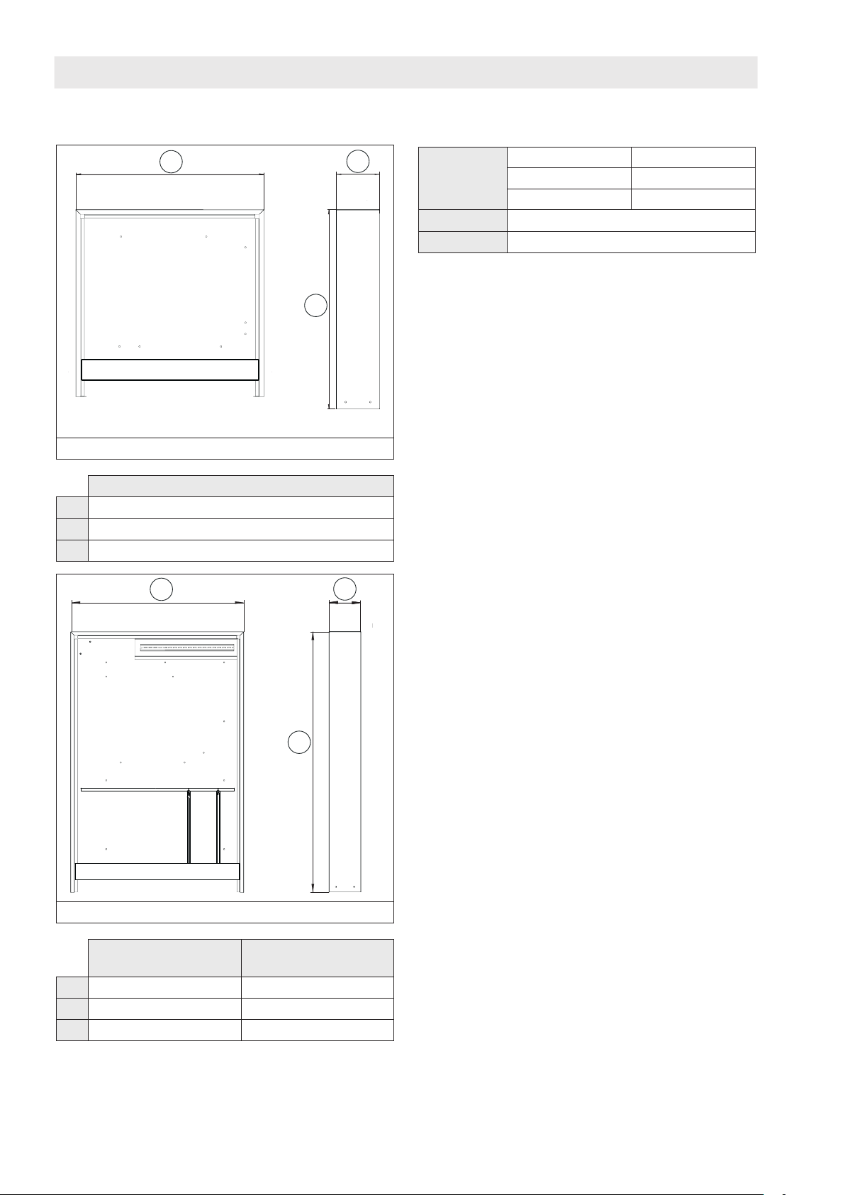
3. Positionieren Sie den Aufputzschrank an dem für
ihn vorgesehenen Ort.
4. Befestigen Sie den Schrank an den Füßen und den
Wandbefestigungspunkten (siehe Abb. 1 auf Seite
7 (1) und Abb. 2 auf Seite 7 (2)).
5. Montieren Sie die Wohnungsstation und ihr Zubehör
in den Aufputzschrank. Beachten Sie die Betriebs-
anleitungen der jeweiligen Artikel.
6. Setzen Sie die Tür des Aufputzschrankes wieder
ein.
Sie können die Kartonage zum Schutz der Tür
während der Bauphase verwenden.
6.2 Schutzpotentialausgleich/Erdung
GEFAHR
Lebensgefahr durch elektrischen Strom!
Bei Berührung spannungsführender Bauteile
besteht Lebensgefahr.
fTrennen Sie die Station allpolig von der
Stromversorgung und sichern Sie die Sta-
tion gegen Wiedereinschalten.
fPrüfen Sie die Spannungsfreiheit.
fDas Anschließen darf nur ein Elektrofach-
handwerker durchführen.
Vor der Inbetriebnahme der Anlage muss der Aufputz-
schrank über einen Schutzpotentialausgleichsleiter
gem.gültigerNormenundlandesspezischenVorschrif-
ten durch einen Elektrofachhandwerker sachgemäß
geerdet werden. Der Aufputzschrank muss über den
zentralen Erdungspunkt mit der Potentialausgleichs-
schiene des Gebäudes verbunden werden. Das not-
wendige Potentialausgleichskabel aus Kupfer muss
einen Querschnitt von mindestens 6mm² aufweisen.
Beachten Sie die Norm DIN VDE 0100-540.
1 2
Abb. 8: Erdung der Tür
(1) Zentraler Erdungspunkt
(2) Erdungspunkt der Tür
Zubehör zur Erdung der Tür liegt dem Aufputz-
schrank bei.
Die Erdung der Wohnungsstation „Regudis
W-HTE“ und ihrem Zubehör erfolgt über die
Erdung des Schrankes.

Aufputzschrank Demontage und Entsorgung
11
134469780-V03.04.2019
1 2 3 4 5 6
Abb. 9: Aufbau des Zentralen Erdungspunktes
(1) Sechskantmutter M5
(2) Federring
(3) Unterlegscheibe
(4) Ringkabelschuh
(5) Unterlegscheibe
(6) Kontaktscheibe mit Schneidzähnen
1. Verbinden Sie den zentralen Erdungspunkt (siehe
Abb. 8 auf Seite 10 (1)) über ein Kabel mit der
Potentialausgleichsschiene des Gebäudes.
DerzentraleErdungspunktbendetsichan
der rechten Seitenwand des Aufrputzschran-
kes (siehe Abb. 8 auf Seite 10).
2. Verbinden Sie ebenfalls den Erdungspunkt der Tür
(siehe Abb. 8 auf Seite 10 (2)) mit dem zentralen
Erdungspunkt (1).
Abb. 10: Zentraler Erdungspunkt mit Verbindung zur
Potentialausgleichsschiene des Gebäudes
und zur Tür des Aufputzschrankes
7. Demontage und Entsorgung
ACHTUNG
Verschmutzungsgefahr für die Umwelt!
Nicht fachgerechte Entsorgung (z. B. im Haus-
müll) kann zu Umweltschäden führen.
fEntsorgen Sie das Verpackungsmaterial
umweltgerecht.
fEntsorgen Sie Bauteile fachgerecht.
Sofern keine Rücknahme- oder Entsorgungsverein-
barung getroffen wurde, entsorgen Sie das Produkt.
fFühren Sie Bestandteile möglichst der Wiederver-
wertung zu.
fEntsorgen Sie nicht wiederverwertbare Bestandteile
den lokalen Vorschriften entsprechend. Das Entsor-
gen im Hausmüll ist nicht zulässig.


Surface-mounted cabinet Content
13
134469780-V03.04.2019
1. General information ..............................................................................................................15
1.1 Validity of the operating instructions .......................................................................................15
1.2 Extent of supply ......................................................................................................................15
1.3 Contact....................................................................................................................................15
1.4 Copyright and protective rights...............................................................................................15
1.5 Used symbols..........................................................................................................................15
2. Safety-related information....................................................................................................15
2.1 Normative directives................................................................................................................15
2.2 Correct use..............................................................................................................................15
2.3 Modicationstotheproduct...................................................................................................15
2.4 Warnings .................................................................................................................................16
2.5 Safety notes ............................................................................................................................16
2.5.1 Risk of injury from heavy product ..........................................................................................................16
2.5.2 Risk of injury in case of improper work..................................................................................................16
2.5.3 Availability of the operating instructions ................................................................................................16
3. Technical description............................................................................................................17
3.1 Construction............................................................................................................................17
3.2 Dimensions..............................................................................................................................18
3.3 Technical data .........................................................................................................................18
4. Accessories and spare parts................................................................................................19
5. Transport and storage...........................................................................................................19
6. Installation..............................................................................................................................20
6.1 Installation ...............................................................................................................................20
6.2 Protective equipotential bonding/Earthing..............................................................................20
7. Removal and disposal...........................................................................................................21
Content
Page


Surface-mounted cabinet General information
15
134469780-V03.04.2019
1. General information
The original operating instructions were drafted in
German.
The operating instructions in other languages were
translated from German.
1.1 Validity of the operating
instructions
These operating instructions are valid for the surface-
mounted cabinets item no. 1344697, 1344698 and
1344699.
1.2 Extent of supply
Please check the delivery for any damages caused
during transit and for completeness.
Extent of supply
• Surface-mounted cabinet for "Regudis W-HTE"
• Fixing material for distributor/collector (only item
no. 1344698 and 1344699)
• Fixing material for dwelling station
• Accessories for equipotential bonding
1.3 Contact
Address
OVENTROP GmbH & Co. KG
Paul-Oventrop-Straße 1
59939 Olsberg
Germany
Technical service
Phone: +49 (0) 29 62 82-234
1.4 Copyright and protective rights
These operating instructions are copyrighted. They
are exclusively designed for persons involved with
the product.
1.5 Used symbols
Important information and further explanations.
fAction required
• Enumeration
1.
2.
Fixed order. Steps 1 to X.
ZResult of action
2. Safety-related information
2.1 Normative directives
Observe the legal framework conditions valid at the
installation location.
The current standards, rules and guidelines are valid.
2.2 Correct use
Safety in operation is only guaranteed if the product
is used correctly.
The surface-mounted cabinet serves the direct
installation and protection of the dwelling station
"Regudis W-HTE" and its accessories.
Any use of the product outside the above
applications will be considered as non-compliant and
misuse.
Claims of any kind against the manufacturer and/
or his authorised representatives, due to damages
caused by incorrect use cannot be accepted.
The observance of the operating instructions is part
of the compliance terms.
2.3 Modications to the product
Modicationstotheproductarenotallowed.In
caseofmodicationstotheproduct,thewarranty
will become void. The manufacturer will not accept
liability for damages and malfunctions caused by
modicationstotheproduct.

Safety-related information Surface-mounted cabinet
16 134469780-V03.04.2019
2.4 Warnings
Each warning contains the following elements:
Warning symbol
SIGNAL WORD
Type and source of danger!
Possible consequences if the danger occurs
or the warning is ignored.
fPossibilities of avoiding the danger.
Thesignalwordsdenetheseriousnessofthe
danger which arises from a situation.
DANGER
Indicates an imminent danger with high risk
which will lead to death or serious injury if the
situation is not avoided.
NOTICE
Indicates a situation which may lead to
damage to property if not avoided.
2.5 Safety notes
This product is designed in accordance with the
necessary safety standard of science and technology
and is fail-safe. Nevertheless, there might still be
a residual danger for persons and property during
installation and operation.
2.5.1 Risk of injury from heavy product
fWear safety shoes during installation.
fInstallation must be carried out by several persons.
2.5.2 Risk of injury in case of improper work
Angular components points and edges at the outside
and inside of the product may cause injuries.
fBefore starting work, make sure that there is enough
space.
fOpen and hard-edged components are to be
handled with care.
fMake sure that the work place is tidy and clean to
avoid accidents.
2.5.3 Availability of the operating instructions
Any person working on the product has to read and
apply these operating instructions and all other valid
documents (e.g. accessory manuals).
The operating instructions have to be kept at the
installation location.
fHand these operating instructions and all other valid
documents (e.g. accessory manuals) over to the
user.

Surface-mounted cabinet Technical description
17
134469780-V03.04.2019
3. Technical description
3.1 Construction
2
34
3
2
1
1
1
Illustr. 1: Construction surface-mounted cabinet
1344697
(1) Wall attachment points
(2) Threaded bolts for "Regudis W-HTE"
(3) Threaded bolts for ball valve connector block
(4) Extendible feet with height marking for
adjustmentoftheoorconstructionheight
(100 - 180 mm)
3
1
6
7
5
4
2
2
2
2
2
Illustr. 2: Construction surface-mounted cabinet
1344698 and 1344699
(1) Fixing device for electrical connecting block
(2) Wall attachment points
(3) Threaded bolts for "Regudis W-HTE"
(4) Threaded bolts for ball valve connector block
(5) Mounting rail for distributor/collector
(6) Extendible feet with height marking for
adjustmentoftheoorconstructionheight
(100 - 180 mm)
(7) Fixing points for a socket

Technical description Surface-mounted cabinet
18 134469780-V03.04.2019
3
2
1
Illustr. 3: Construction closed surface-mounted
cabinet
(1) Door
(2) Frame
(3) Plinth
3.2 Dimensions
12
3
Illustr. 4: Dimensions surface-mounted cabinet
1344697
Surface-mounted cabinet 1344697
(1) 750 mm
(2) 160 mm
(3) 745 - 860 mm
12
3
Illustr. 5: Dimensions surface-mounted cabinet
1344698 and 1344699
Surface-mounted
cabinet 1344698
Surface-mounted
cabinet 1344699
(1) 750 mm 880 mm
(2) 160 mm 160 mm
(3) 1326 - 1441 mm 1326 - 1441 mm
3.3 Technical data
Weight Item no. 1344697 14,0 kg
Item no. 1344698 27,0 kg
Item no. 1344699 29,5 kg
Material Steel sheet, galvanised
Colour White RAL 9010, matt

Surface-mounted cabinet Accessories and spare parts
19
134469780-V03.04.2019
4. Accessories and spare parts
Spare parts and accessories are obtainable from
specialist stores.
The following item is available as accessory:
• Cylinder lock with key (item no. 1401191)
Illustr. 6: Cylinder lock with key
5. Transport and storage
Transport the product in the original packing.
Store the product under the following conditions:
Temperature range -20°C to +60°C
Relative humidity of
air
max. 95%
Particles Dry and free from dust
Mechanical
inuences
Protected from mechanical
agitation
Radiation Protected from UV-rays and
direct sunlight
Chemical inuences Do not store together with
solvents, chemicals, acids,
fuels and similar

Installation Surface-mounted cabinet
20 134469780-V03.04.2019
6. Installation
6.1 Installation
1. Remove the door of the surface-mounted cabinet.
2. Adjust the feet of the surface-mounted cabinet
to the required height. Observe the height of the
screed when adjusting the feet. The screed surface
should be at least 1 cm above the lower edge
of the plinth. A height marking will appear when
extending the feet (see Illustr. 7 on page 20).
The dimensions on the height marking indicate the
distancebetweentheoorandtheloweredgeof
the plinth. Adjust the feet by loosening the wing
nutsandxthembytighteningthewingnuts.
Illustr. 7: Height marking
3. Position the surface-mounted cabinet at the
designation installation location.
4. Fix the cabinet at the feet and the wall attachment
points (see Illustr. 1 on page 17 (1) and Illustr. 2
on page 17 (2)).
5. Fit the dwelling station and its accessories into the
surface-mounted cabinet. Observe the operating
instructions of the different components.
6. Retthedoorofthesurface-mountedcabinet.
You can use the cardboard for the protection of
the door during the construction phase.
6.2 Protective equipotential bonding/
Earthing
DANGER
Danger to life due to electric current!
Danger to life due to contact with live
components.
fCompletely disconnect the station from
the power supply and protect it against
accidental restart.
fCheck that no voltage is present.
fThe electrical connection must only be
carriedoutbyaqualiedelectrician.
Before commissioning of the installation, the surface-
mounted cabinet must be earthed via a protective
equipotentialbondingconductorbyaqualied
electrician according the valid standards and local
regulations. The surface-mounted cabinet must be
connected to the equipotential bonding rail of the
building via the central earthing point. The required
equipotential bonding cable made of copper has to
feature a minimum cross section of 6 mm² . Observe
the DIN VDE 0100-540 standard.
1 2
Illustr. 8: Earthing of the door
(1) Central earthing point
(2) Earthing point of the door
Accessories for earthing of the door are
supplied with the surface-mounted cabinet.
Earthing of the dwelling station “Regudis
W-HTE” and its accessories is carried out via
the earthing of the cabinet.
This manual suits for next models
2
Table of contents
Languages:
Other oventrop Protection Device manuals