manuals.online logo
Brands
  1. Home
  2. •
  3. Brands
  4. •
  5. Symantec
  6. •
  7. Protection Device
  8. •
  9. Symantec DLP-S500 User manual

Symantec DLP-S500 User manual

Page 1
01 Unpack the DLP-S500 Appliance
Unpack the shipment package and verify its contents. The Symantec DLP-S500 series
appliance ships with the following components:
oSymantec DLP-S500 appliance oSoftware License Agreement
oTwo AC power cords oHardware Warranty document
oNull modem serial cable
oSafety and Regulatory Compliance Guide
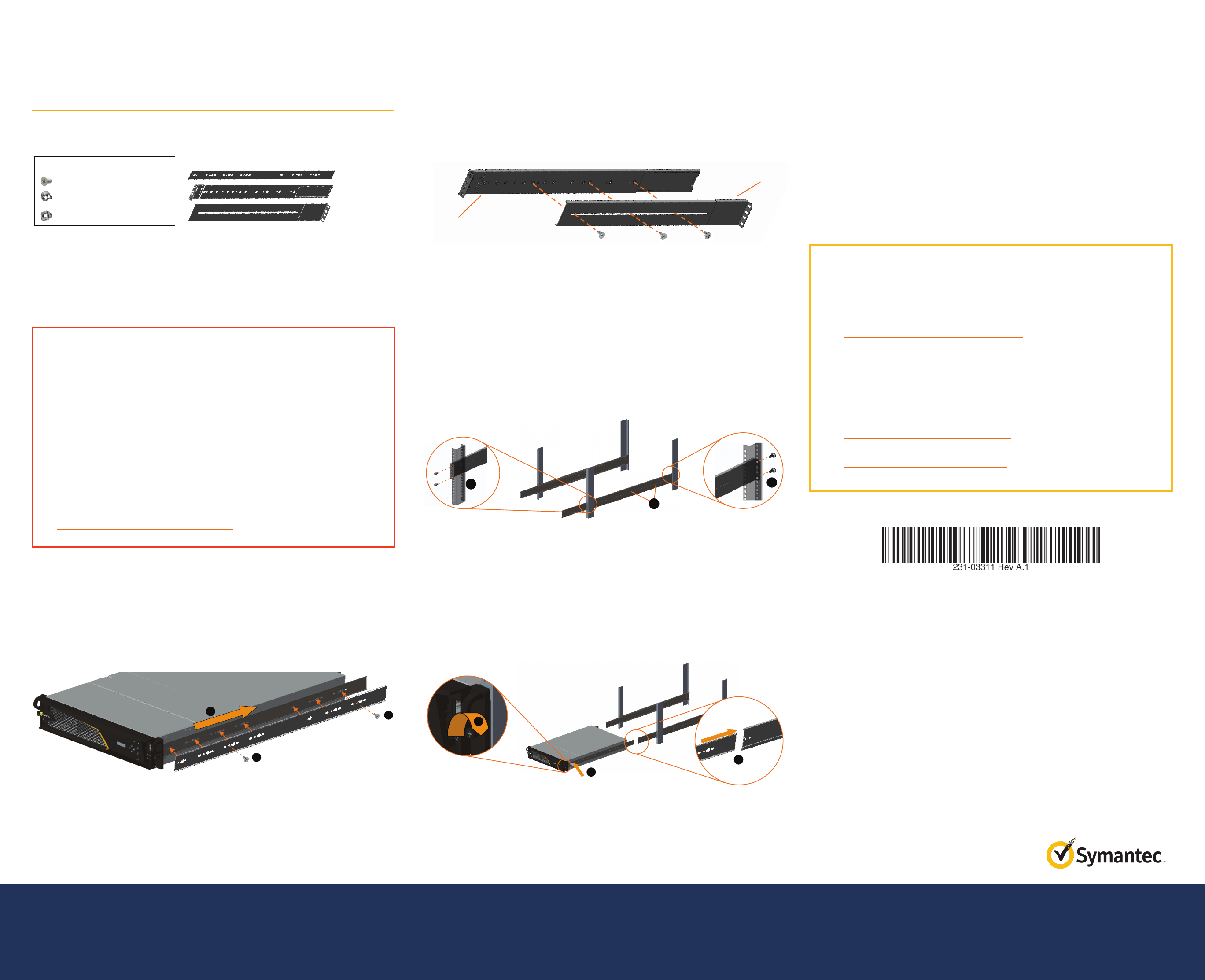
oTwo/four-post slide-rail kit oQuick Start Guide (this document)
oGrounding hardwares
02 Connect Cables
Symantec recommends that you plug in cables, verify the LEDs and LCD, and perform
an initial configuration before rack-mounting the appliance. If you would rather install
the appliance in the rack before performing configuration tasks, skip to Step 6—Rack-
Mount the Appliance.
Note: Network cables are not included and must be supplied by the user.
To deploy the DLP-S500 and connect its cables:
a. Remove the End User License Agreement (EULA) sticker from the anti-static bag in-
cluded with the appliance. By removing the sticker and installing the product, you are
agreeing to the terms and conditions of the EULA.
b. Attach the lug-equipped end of the
grounding wire (10 AWG) to both
grounding studs on the appliance,
securing it with the star washers
and M5 nuts. Attach the other end
of the grounding wire to a proper
earth-ground.
c. Connect the appliance’s SYS MGMT 0:0 port to a management workstation with a
browser, either directly or through a management network.
d. Connect the appliance’s serial port to a serial terminal or to a workstation with termi-
nal-emulation software, using the included null-modem serial cable (optional).
e. Connect the socket end of the included power cords to the appliance’s power supply
inlets. Connect the other ends of the power cords to a power source.
03 Power on the Appliance and Verify LEDs
To verify the DLP-S500 is operational:
a. Confirm the appliance’s power cords are securely connected to a power source.
b. If the appliance does not automatically power on, press the rear soft power switch.
Note: The state of the appliance’s soft power switch (on or off) is retained when power
is removed. This may necessitate pressing the power switch when reapplying power to
the appliance.
c. As the appliance boots, verify the following:
oThe Power LED turnsamber.
oNear the end of the boot cycle, the Power LED alternates between amber and
green, indicating an unconfigured state.
oFollowing the initial configuration (see Step4), the Power LED turns green. In
addition, the LCD displays system statistics, which can be scrolled through with
the Left/Right Arrows.
04 Perform the Initial Configuration
You must have the following network information on hand to perform the appliance’s
initial configuration:
oDLP-S500 IP address oDefault Gateway IP address
oSubnet mask oPrimary DNS server IP address
oConsole password to access the
advanced commands in the CLI
oAdmin password for authorizing
access to the appliance
To perform the initial configuration for the DLP-S500:
a. Confirm that a null-modem serial cable is connected from the appliance to a worksta-
tion’s serial port.
b. Open a terminal emulation program such as Microsoft HyperTerminal®, PuTTY, Tera
Term, or ProComm™.
c. Configure the terminal emulation software to the following settings:
oBaud rate: 9600 bps
oParity: none
oFlow control: none
oData bits: 1
oStops bits: 8
d. Power on the appliance (if it is not already powered on).
e. After the appliance boots, when prompted, press <Enter> three times. The configura-
tion process begins.
f. When prompted, select option 2: Setup Console and configure the following
settings:
oSpecify the IP address the DLP-S500 appliance will use.
oSpecify a console password. The console password allows you to log in to the CLI
via the Secure Shell (SSH) protocol.
oSpecify an enable password. The enable password gives you administrative access
via the CLI.
Note: Ignore the message that says you can use port 8082 for administration. This port
is currently not available for the DLP-S500.
Note: Following the initial configuration, the System Status LED blinks amber,
indicating the appliance has not yet been licensed (see Step5).
05 License the DLP-S500 Appliance
After the DLP-S500 has been configured for network access and the console and enable
passwords have been specified, log in to the CLI and install the hardware license.
To license the DLP-S500:
a. Enter:
ssh admin@[your host name here]
b. Enter your console password:
[your console password here]
c. At the prompt, enter enable:
localhost> enable
d. Enter your enable password:
localhost# [your enable password here]
e. To apply the hardware license previously saved to an http server URL, enter:
localhost# licensing load url [your url here]
f. To confirm that the license has been installed, enter:
localhost# licensing view
g. Reboot the appliance for the license to take effect, enter:
localhost# restart
h. Go to the Symantec Data Loss Prevention Enforce Server administration console to
configure the communication between the DLP-S500 and the Enforce Server admin-
istration console. For more information on using Symantec Data Loss Prevention, go
to: https://support.symantec.com/en_US/dpl.56500.html
i. To proceed to rack-mounting the DLP-S500, carefully power off the appliance with
the shutdown command:
oLog in to the DLP-S500 command-line interface.
oWhen prompted, press 1 to access the CLI.
oTo access privileged commands, enter: enable
oTo power off the appliance, enter: shutdown
Warning: Do not power off the appliance with the soft power switch or by
removing the power cables! Abruptly removing power can result in irreparable
data loss. Always use the shutdown command from the CLI to power off the
appliance.
Note: For additional installation information and configuration options, see the Data
Loss Prevention documentation at:
https://support.symantec.com/en_US/dpl.56500.html
Quick Start Guide
Data Loss Prevention DLP-S500
IOIOI SYS MGMT 0:0
BMC MGMT
1: 2:
3:
4:
5:
6:
7:
PS 2
PS 1
SYS MGT
Workstation
Serial
Workstation
Soft
Power Switch
Amber—Warning
Green—Healthy
Off—No status
Status LED
Green—Powered on and configured
Alternating amber/green—Unconfigured
Amber—Booting
Off—Powered off
Power LED
Blinking amber—Critica
l
Copyright © 2017 Symantec Corp. All rights reserved. Symantec, the Symantec Logo, the Checkmark Logo, Blue Coat, and the Blue Coat logo are trademarks or registered trademarks of Symantec Corp. or its affiliates in the U.S. and other countries. Other names may be trademarks of their respective owners. This document is provided for informational purposes only and is not intended as advertising. All warranties relating to the information in this
document, either express or implied, are disclaimed to the maximum extent allowed by law. The information in this document is subject to change without notice. Part Number: 231-03311 Rev A.1
THE DOCUMENTATION IS PROVIDED “AS IS” AND ALL EXPRESS OR IMPLIED CONDITIONS, REPRESENTATIONS AND WARRANTIES, INCLUDING ANY IMPLIED WARRANTY OF MERCHANTABILITY, FITNESS FOR A PARTICULAR PURPOSE OR NON-INFRINGEMENT, ARE DISCLAIMED, EXCEPT TO THE EXTENT THAT SUCH DISCLAIMERS ARE HELD TO BE LEGALLY INVALID. SYMANTEC CORPORATION SHALL NOT BE LIABLE FOR INCIDENTAL OR
CONSEQUENTIAL DAMAGES IN CONNECTION WITH THE FURNISHING, PERFORMANCE, OR USE OF THIS DOCUMENTATION. THE INFORMATION CONTAINED IN THIS DOCUMENTATION IS SUBJECT TO CHANGE WITHOUT NOTICE. SYMANTEC CORPORATION PRODUCTS, TECHNICAL SERVICES, AND ANY OTHER TECHNICAL DATA REFERENCED IN THIS DOCUMENT ARE SUBJECT TO U.S. EXPORT CONTROL AND SANCTIONS LAWS, REGULATIONS AND
REQUIREMENTS, AND MAY BE SUBJECT TO EXPORT OR IMPORT REGULATIONS IN OTHER COUNTRIES. YOU AGREE TO COMPLY STRICTLY WITH THESE LAWS, REGULATIONS AND REQUIREMENTS, AND ACKNOWLEDGE THAT YOU HAVE THE RESPONSIBILITY TO OBTAIN ANY LICENSES, PERMITS OR OTHER APPROVALS THAT MAY BE REQUIRED IN ORDER TO EXPORT, RE-EXPORT, TRANSFER IN COUNTRY OR IMPORT AFTER DELIVERY TO YOU.
Page 2
DLP-S500 Quick Start Guide
06 Rack-Mount the DLP-S500 Appliance
The included slide-rail rack-mounting kit allows you to install the appliance in a two- or
four-post rack. The kit is comprised of the following parts:
To install the DLP-S500 in a four-post equipment rack, you may need the following tools
and hardware:
oM4 nut driver oRack specific screws
oAdjustable wrench oHeadlamp (recommended)
o#2 Phillips head screwdriver
Note: You must remove the inner rail from Rail A before rack-mounting the appliance.
Refer to the S-Series Maintenance and Upgrade Guide for instructions.
To install the DLP-S500 into a four-post equipment rack:
a. Attach the inner rails to the appliance:
oAlign the inner rail to the four mounting posts on the side of the chassis and lock
the rail into position by sliding it toward the rear of the appliance (A). Make sure
that all six mounting posts snap into the slots in the inner rail.
oInstall two (2) M3 screws to secure the inner rail to the appliance (B).
oRepeat the previous steps for the opposite inner rail.
b. Assemble the slide-rails:
oLoosely attach RailC to RailA. The precise attachment location will depend
on how far RailC must be extended or retracted to fit the rack model. It may
be necessary to remove RailC from RailA to determine the proper installation
length for the rack.
oTemporarily mount RailC to RailA:
• Align the front- and rear-mounting faces against the rack. Make sure
that the slide-rail mounting faces are on the outside of the rack’s vertical
rails.
• After you have determined the installation length, temporarily install three
(3) M3 screws in the slot in RailC. Make sure the screws are equidistant from
each other to distribute the load on the rail.
oRepeat the previous steps for the opposite slide-rail.
c. Mount the slide-rail assemblies in the four-post rack:
oPlace the assembled slide-rail against the rack and secure the RailA front bracket
to the outside face of the rack using two (2) rack screws (A). Do not fully tighten the
screws just yet. You will do so after the appliance is installed in the rack.
oExtend or retract RailC to align the mounting face of the bracket with the outside
face of the rack and secure it with two (2) rail screws (B). Do not fully tighten the
screws just yet. You will do so after the appliance is installed in the rack.
oTighten the RailC side-mounting screws (C).
oRepeat the previous steps for the opposite slide-rail assembly. Verify that both
slide-rail assemblies are installed at the same height in the rack.
d. Install the appliance in the rack:
oAlign the grooves on the inner rail with the grooves on RailA and slide the
appliance half-way into the rack (A).
oPress the gray tab on the inner rails to slide the appliance all the way into the
rack(B).
oSlide the appliance out of the rack, far enough to access the rack-mounting screws.
Fully tighten the RailA and RailC rack-mounting screws to secure the slide-rails to
the rack.
oGently push the appliance all the way to the back of the rack.
oTighten the thumbscrews on the retaining ears to prevent the appliance from
sliding out of the rack (C).
e. Reconnect the cables as documented in Step 2—Connect the Cables and verify the
appliance is functioning as in Step 3—Verify the LEDs and LCD.
A
B
C
AB
C
A
B
B
Rail A
Rail C
Technical Support
oContact Information
https://support.symantec.com/en_US/contact-support.html
oMySymantec
https://mysymantec.force.com/customer/s/
Documentation
Symantec Data Loss Prevention Software Documentation
ohttps://support.symantec.com/en_US/dpl.56500.html
DLP-S500 Appliance Documentation
oS-Series Maintenance and Upgrade Guide
http://www.symantec.com/docs/DOC9795
oS500 Series Safety and Regulatory Compliance Guide
http://www.symantec.com/docs/DOC10248
Hardware Pack
M3 T-Type Screw x 10
M6 Screw x 8
M6 Cage Nut x 8 (optional)
Inner Rail x 2
Rail A x 2
Rail C x 2
CAUTION:
Before rack-mounting the appliance:
oPower off the appliance and disconnect all cables.
oVerify that the weight of the system does not exceed the rack’s
fully populated weight limit. For more information, refer to the
manufacturer’s instructions included with the rack.
oFor weight stability, load the rack from thebottomup.
oRead the “Rack Mount Warnings” section of the included Safety and
Regulatory Compliance Guide.
oTake adequate safety and grounding measures to avoid creating an
electrical shock hazard and to prevent bodily injury.
For comprehensive information on the slide-rail rack mounting kit, see
the S-Series Maintenance and Upgrade Guide at:
http://www.symantec.com/docs/DOC9795

Popular Protection Device manuals by other brands

nxt BIA-nXt-DPC 1-22 Installation and operation manual

nxt

nxt BIA-nXt-DPC 1-22 Installation and operation manual

Cristec RCE/100-1E-2IG user manual

Cristec

Cristec RCE/100-1E-2IG user manual

Entek IRD 6600 Series Guide

Entek IRD

Entek IRD 6600 Series Guide

GE Grid Solutions F60 instruction manual

GE Grid Solutions

GE Grid Solutions F60 instruction manual

FireFlex TOTALPAC X Owner's operation and maintenance manual

FireFlex

FireFlex TOTALPAC X Owner's operation and maintenance manual

ABB Relion 670 series Product guide

ABB

ABB Relion 670 series Product guide

ABB relion REF615 Product guide

ABB

ABB relion REF615 Product guide

STAMOS SWA04L user manual

STAMOS

STAMOS SWA04L user manual

ABB RELION REB670 Product guide

ABB

ABB RELION REB670 Product guide

Amina APU150 user guide

Amina

Amina APU150 user guide

Num'axes CAS1021 user guide

Num'axes

Num'axes CAS1021 user guide

Crye Precision LVS BASE VEST Operator's manual

Crye Precision

Crye Precision LVS BASE VEST Operator's manual

ABB RELION 650 SERIES Commissioning manual

ABB

ABB RELION 650 SERIES Commissioning manual

Pepperl+Fuchs R3-SP-IBD12 Installation

Pepperl+Fuchs

Pepperl+Fuchs R3-SP-IBD12 Installation

Sony BKM-PP25 Mounting instructions

Sony

Sony BKM-PP25 Mounting instructions

UrbMob MK9S manual

UrbMob

UrbMob MK9S manual

SENSTAR FPS-3 Installation & operation guide

SENSTAR

SENSTAR FPS-3 Installation & operation guide

Leviton 3801-DIN Installation

Leviton

Leviton 3801-DIN Installation

manuals.online logo
manuals.online logoBrands
  • About & Mission
  • Contact us
  • Privacy Policy
  • Terms and Conditions

Copyright 2025 Manuals.Online. All Rights Reserved.