OVERBECK MACHINE LT-1BR User manual

© 2020 Overbeck Machine Tools, LLC Version 2.3
1
TWISTER OWNERS MANUAL
LT-1BR
LT-2AR
MODEL: ______________________________
SERIAL NUMBER:_____________________
BORN ON DATE:______________________
OVERBECK MACHINE TOOLS
953 TOWER PLACE, UNIT E
SANTA CRUZ, CA 95062
(831) 425.5912 FAX (831)423.9363
1INFO@OVERBECKMACHINE.COM
WWW.OVERBECKMACHINE.COM
WARNING ! Using this product can expose you to chemicals that are known to the state of
California to cause cancer and birth defects or reproductive harm. For more information go to
https://p65warnings.ca.gov/

© 2020 Overbeck Machine Tools, LLC Version 2.3
2
SERVICE RECORD
Date:_________________
Service Performed:____________________________________________
_____________________________________________________________
_____________________________________________________________
Date:_________________
Service Performed:____________________________________________
_____________________________________________________________
_____________________________________________________________
Date:_________________
Service Performed:____________________________________________
_____________________________________________________________
_____________________________________________________________
Date:_________________
Service Performed:____________________________________________
_____________________________________________________________
_____________________________________________________________
Date:_________________
Service Performed:____________________________________________
_____________________________________________________________
_____________________________________________________________
Date:_________________
Service Performed:____________________________________________
_____________________________________________________________
_____________________________________________________________
Date:_________________
Service Performed:____________________________________________
_____________________________________________________________
_____________________________________________________________
Date:_________________
Service Performed:____________________________________________
_____________________________________________________________
_____________________________________________________________

© 2020 Overbeck Machine Tools, LLC Version 2.3
3
Read this complete manual before attempting to operate your Twister
Speed Lathe!
We urge you to review the following warnings, procedures and operations. All
persons involved in setting up, operating, or servicing the machine are required to
read this manual prior to starting any service work or use.
If you have any questions about this machine, call us at 1-831-425-5912
We strongly suggest that anyone who will set-up, operate, or be in the vicinity of the Twister
Speed Lathe while it is being used should read all of the following recommendations:
! WARNING this machine can expose you to chemicals that are known to the State of California
to cause cancer and birth defects or other reproductive harm. For more information go to
https://www.p65warnings.ca.gov/
! NEVER attempt to operate this machine in a damp or wet area.
! NEVER use liquid of any type in your use of the Twister machine.
! NEVER operate the Twister machine unless you are using approved safety glasses, hearing
protection and a dust mask. Consult with your safety manager for proper or approved PPE.
! NEVER attempt to operate this machine without first having its installation and your set-up
checked by a person qualified to do so.
! NEVER service or maintain the Twister machine without first disconnecting the machine from
the power source. Modification of the Twister in any way will void your warranty. Use of non-
factory replacement parts will also void your warranty and lead to degraded or unsafe
mechanical or electrical function. Use of non-factory parts can lead injury, including death.
! NEVER use chucks or fixtures in the spindle of the Twister machine.
! NEVER wear gloves while operating the Twister machine.
! NEVER open or close the collet closer while the spindle is rotating.
! NEVER start the Twister machine unless the collet lever is in the closed position.
! NEVER start the Twister machine unless a collet is in the spindle.
! NEVER press the spindle lock plunger with the Twister spindle still rotating.

© 2020 Overbeck Machine Tools, LLC Version 2.3
4
! DO NOT allow any material or your part to protrude more than three (3”) inches from the
Twister spindle end or closer end at any time.
! DO NOT attempt to polish or deburr out-of-balance or out-of-round parts.
! DO NOT operate this machine while wearing a ring, a watch, jewelry, a tie, loose clothing, or
long hair, which is not contained by a hair net or shop hat.
! DO NOT leave the Twister machine unattended while it is running.
END OF DAY CLEAN UP: At the end of your day or shift, take a few moments to wipe the
Twister machine down to remove any dust or debris that has built up. Remove the collet that
was used for your work and wipe the inside of the spindle taper. Note any functional or safety
issues observed and report them to the shift manager or responsible party. Doing this on a
daily basis will keep your machine in a safe and good state of operation. Best of all, you will
start your day using a clean machine.
1. SAFETY and SAFEGUARDS
1.1 Dangers Associated With This Machine
The Twister polishing/deburring machine is designed exclusively for the applications
outlined in this manual. Any circumstances interfering with the safe use of this
machine are to be remedied immediately. Any modification to the machine by the
end-user can create safety issues that can lead to injury including death. Modifications
to the Twister machine by the end-user are expressly not approved and not the
responsibility of Overbeck Machine Tools.
1.2 Appropriate Use of This Machine
The Twister Speed Lathe is designed and intended for sanding, polishing, deburring,
filing, scraping, gauging and assembly operations. Any use outside of the above
intended purposes is not approved and is done at your own risk.
1.3 Emissions
The Twister Speed Lathe has an operational noise level of approximately 68 db(A).
Also, there are dust and fumes associated with polishing and sanding materials.
1.4 Hazards and Dangers
Warning ! The Twister Speed Lathe has unguarded, spinning parts:
Any attached work holding devices (collets), the collet closer assembly and knurled
ring. Those parts and assemblies can inflict injury to hands, fingers and eyes.
Insufficient clamping force on a part or an unbalanced part that may be thrown off the
machine can cause serious injury. Keep your fingers and hands away from the above
noted spinning parts.
1.5 Safety Requirements During Use
To avoid accidents by inadvertently knocking the Twister Speed Lathe off the work
surface or work bench, it is recommended to bolt the machine to the table and/or
place the machine no less than three inches (3”) from the forward edge of the work
surface.

© 2020 Overbeck Machine Tools, LLC Version 2.3
5
1.6 Machine Safeguards
The Twister Speed Lathe can be switched off using the front panel ON-OFF switch
during an emergency situation. Further, the spindle can be stopped by lifting off the
foot switch or switching the front panel forward-reverse switch to the neutral position.
1.7 Qualified Personnel
All personnel setting up or operating the Twister Speed Lathe must be qualified and
authorized to do so. The owner’s manual must be provided to the operator. It is the
owner’s responsibility to ascertain the operator’s understanding of the manual.
1.8 Personal Protective Equipment (PPE)
Safety glasses that meet at minimum ANSI Z87+ specification or provided by your
company for use during the operation of the Twister Speed Lathe. Further, use of
hearing protection that meets NRR 32db reduction at minimum or equipment provided
by your company. Last, a dust respirator that meets the N95 specification or equipment
provided by your company. Use of the above three (3) safety items are required during
the use of the Twister Speed Lathe. Use of the above three (3) items does not
guarantee your safety or impact to your health. Improper use of the Twister machine
can cause injury or death. It is your responsibility to work in a safe manner using
proper PPE.
2.0 Installation
Have you read and fully understand Section 1, Safety and Safeguards? The Twister
Speed Lathe may not be operated without doing so.
Note: The foot switch will start the LT-1BR and LT-2AR any time the power switch is in
the ON position and the Forward/Reverse switch is in FORWARD or REVERSE position.
2.1 Setting up and mounting the LT-1BR (See figure 1)
The LT-1BR MUST be removed from the shipping base before using it or stability of the
Twister on your work surface will be suspect as well as slippage of the drive belt can
result.
A) Set up the LT-1BR where you need it, make sure it is placed on a clean, dry and
level surface. Do not place the Twister closer than three inches (3”) to the edge of
the mounting surface to minimize accidental contact by surrounding personnel.
B) The machine can be fastened down with a 5/16-18 fastener screwed into the
tapped hole on the bottom of the machine. Drill a 5/16 diameter hole through the
work bench approximately 13 inches (13”) from the front bench edge and located
side-to-side so that it will line up with the center of your LT-1BR. Select a
fastener that has a length equal to the thickness of the work surface plus 1-1/4”
If the mount bolt is too tight, the Twister drive belt will slip. The fastener must
not protrude more than 1-1/2” above the work surface, or damage to the
Twister motor will result.
2.2 Setting up and mounting the LT-2AR (See figure 2)
A) Set up the LT-2AR where you need it, making sure it is placed on a clean, dry and
level surface. Do not place the Twister LT-2AR closer than three inches (3”) to the
edge of the work surface to minimize accidental contact by surrounding personnel.
B) The LT-2AR has three .50” diameter holes available to fasten it down. Since the
casting is a lightweight aluminum alloy, care must be exercised not to distort the
casting when bolting it down. If you are attaching it to a work bench, we
recommend rubber pads under the LT-2AR and rubber bushings around the .25”

© 2020 Overbeck Machine Tools, LLC Version 2.3
6
diameter fasteners. The fasteners should only be tightened enough to slightly
compress the rubber pads. The LT-2AR should have no lateral movement. If you
are mounting to a flat machined surface, no rubber pads are needed. Simply
fasten the machine to the work surface using 3/8” diameter fasteners. Torque
them to 10 Ft-Lb maximum.
3.0 Operation
Have you read and understand Section 1, Safety and Safeguards? The machine may not
be operated without a full understanding of Section 1 and 2.
3.1 Collet Specification for all Models
The 5C collets used on all Twister models must conform to the drawings shown in
Figure 3 and 4. The two most important features are the 1.2500” inch diameter and
width of the thread relief. If your collets have a thread relief wider than .100” inch
you run the risk of the collet rotating and allowing the spindle key to get permanently
stuck in the thread relief. If this happens, your machine will require factory repair.
We strongly recommend using only collets from a known manufacturer that meet these
specifications. Oversize 5C collets up to three (3”) inches in diameter may be used in
the Twister Speed Lathe. The collets MUST have the 10 degree taper as shown in
figure 3.
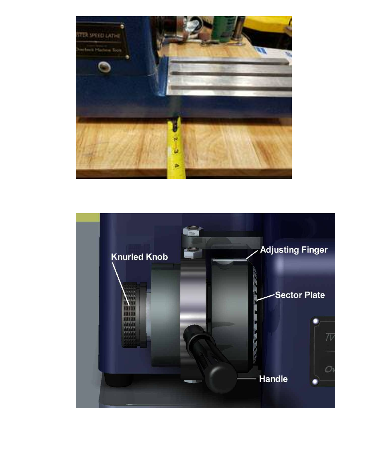
3.2 Adjusting Collet Tension
A) Make Sure the Main POWER Switch is in the OFF position.
B) Insert the 5C collet into the spindle and rotate the collet to align the collet keyway
to the spindle key. COLLET AND SPINDLE BORE MUST BE CLEAN! Slide the closer
handle (Fig. 5) to the Right
C) Release the adjusting finger (Fig. 5) by pressing down into the depression on the
collet closer.
D) With your Left hand rotate the knurled knob (Fig5) clockwise while pressing the
collet in, to engage the collet threads. Use your Right hand to prevent the collet
from getting pushed out of the spindle. Thread the closer onto the collet about 2
turns only.
E) Insert a workpiece into the collet and push the closer handle to the Left. Continue
rotating the knurled knob clockwise until it gets snug. Should the spindle begin to
rotate, push and hold the spindle lock (Fig. 5) It will lock the spindle and prevent
rotation.
F) Move the closer handle all the way to the Right and rotate the collet closer
clockwise two to four more notches on the sector plate (Fig. 5). Check to see if
the collet is gripping the workpiece with the desired firmness by moving the closer
handle to the Left.
G) Once you find that the collet is gripping the workpiece properly, lock the adjusting
finger by pushing down on the Right side of the finger. Make sue that the finger
engages a slot in the sector ring fully, if not, release the closer handle and slightly
rotate the knurled ring clockwise or anti-clockwise in order for the adjusting finger
to fall into one of the slots on the sector ring. Re-lock the adjusting finger in the
sector ring and lock/close the closer by moving the handle to the Left. Your work
should be held tight at this point.
H) The Twister Speed Lathe is now ready for processing your workpiece. It is not
necessary to adjust the collet again for that specific workpiece as long as the work
diameter does not vary. All you need to release the part or clamp the part is move
the closer handle to the Left to clamp and Right to release. Remember, only move
the closer lever when the spindle is not rotating.
3.3 Start and Stop the Spindle using the Brake-Run Switch
A) After the part is firmly locked in the collet, turn the Main POWER switch to ON, set
the SPINDLE ROTATION switch to NORMAL or REVERSE, and turn the BRAKE-RUN
switch to RUN.
B) Select the desired speed by turning the SPINDLE SPEED knob.
C) In order to stop the spindle, move the BRAKE-RUN switch to the BRAKE position.

© 2020 Overbeck Machine Tools, LLC Version 2.3
7
3.4 Start and Stop the Spindle using the Foot Switch
A) If the foot switch is being used, leave the BRAKE-RUN switch in the BRAKE
position. Press the foot switch for spindle start and rotation, release the foot
switch for the spindle to stop.
3.5 Changing the Spindle Direction
A) Switch the SPINDLE ROTATION switch to the desired rotation direction, NORMAL or
REVERSE spindle rotation direction.
3.6 Operational Notes
Generally, polishing is done at high speeds, deburring at low speeds, the bigger the
part diameter, the lower the speed needed. Select a slow speed for filing and scraping
without chatter. If chatter becomes a problem make sure your scraper is very sharp
and if necessary, reduce the spindle speed. Polishing is usually done at as fast a
spindle speed as possible without burning or smearing the part or sandpaper.
Remember, your Twister normally functions smoothly and easily. If a collet will not fit
or parts can’t be gripped without constant re-adjustments (assuming parts do not vary
in size), check for dirty or damaged collet threads, or a badly worn collet. Keep the
collet and draw tube threads clean to eliminate potential problems. If you have any
functional problems, please feel free to call and discuss your Twister machine issues.
FIGURE 1

© 2020 Overbeck Machine Tools, LLC Version 2.3
8
FIGURE 2
FIGURE 5

© 2020 Overbeck Machine Tools, LLC Version 2.3
9

© 2020 Overbeck Machine Tools, LLC Version 2.3
10
TWISTER COLLET CLOSER END
TWISTER SPINDLE END
PLUNGER, SPINDLE LOCK
ADJUSTING FINGER
SECTOR PLATE
KNURLED RING
HANDLE

© 2020 Overbeck Machine Tools, LLC Version 2.3
11
TWISTER FRONT PANEL
MAIN POWER ON / OFF
SWITCH
SPEED ADJUSTMENT KNOB
FORWARD / REVERSE
SPINDLE ROTATION SWITCH
CIRCUIT BREAKER BRAKE / RUN SWITCH
MAIN POWER ON
BRAKE
RUN
FORWARD SWITCH POSITION
REVERSE SWITCH POSITION
NEUTRAL SWITCH POSITION
DEPRESS FOOT SWITCH
SWITCH POSITION
FORWARD ROTATION
SPINDLE ROTATION
SWITCH POSITION
NO ROTATION
REVERSE ROTATION
FORWARD SWITCH POSITION – FORWARD ROTATION
NEUTRAL SWITCH POSITION – NO ROTATION
REVERSE SWITCH POSITION – REVERSE ROTATION
This manual suits for next models
1
Table of contents
Popular Lathe manuals by other brands

Rikon Power Tools
Rikon Power Tools 70-306 Operator's manual

Little Machine Shop
Little Machine Shop Mini Lathe user guide

Central Machinery
Central Machinery 65044 Set up and operating instructions

Rikon Power Tools
Rikon Power Tools 70-100 instruction manual

Jet
Jet CL-1640ZX operating instructions

General International
General International MAXI-LATHE VS+ 25-200 Setup & operation manual