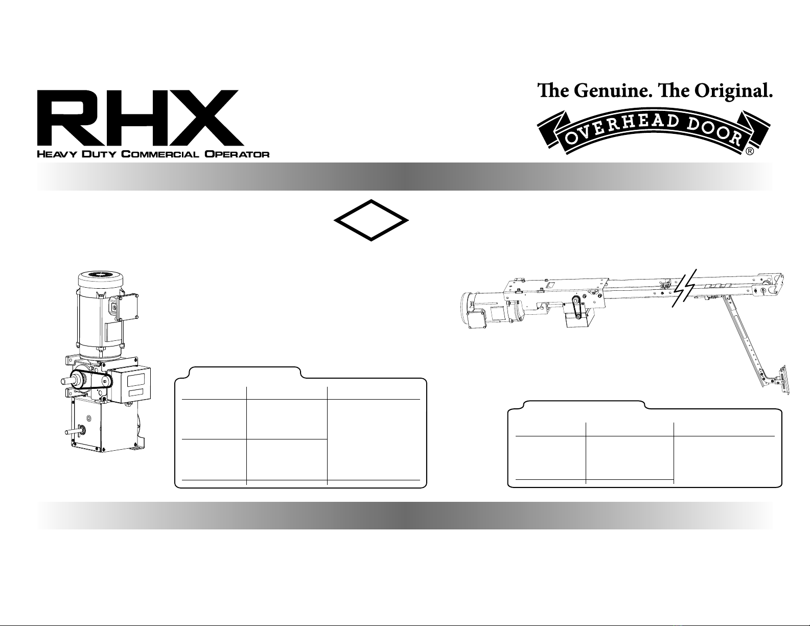
Overhead door RHX NEMA 7 User manual

03/2016 112495.503159
This Installation Manual provides the information required to install, troubleshoot and
maintain an RHX® NEMA 7/9 Commercial/Industrial Door Operator.
NOT FOR RESIDENTIAL USE
Door Type HP/Max Door Weight
Sectional
(All Types) Hoist
(Sidemount,
Centermount, 1/2HP = 1310 lbs.
Chain or Direct Couple)
1HP = 1650 lbs.
Rolling Steel Hoist 3HP = 3696 lbs.
(All Types) (Front of Hood,
Top of Hood, or
Bench Mount)
PROPER APPLICATION
Operator Type
®NEMA7/9
HOIST
WITH EXCLUSIVE FEATURES:
CLASSES:
FLAMMABLE GASES
CLASS 1, DIVISION 1, GROUP D, T2C
COMBUSTIBLE DUST
CLASS II, DIVISION 1, GROUP F & G, T2C
FM
APPROVED TROLLEY
Door Type HP/Max Door Weight
Sectional
(Standard or
Low Headroom
Track Only)
Trolley
(Standard, Sidemount
or Dual Trolley)
1/2HP = 1310 lbs.
1HP = 1650 lbs.
PROPER APPLICATION
Operator Type

Typical Installation
HOIST
E=NEMA 7/9 Explosion
Proof Enclosure
A
B
C
DE
F
G
H=Factory Installed
Intrinsically Safe Control
Wire Junction Box.
H
WARNING
End User/ Installer MUST follow applicable
NEC requirements along with Local
requirements for Hazardous Wiring.
!
AVERTISSEMENT
!
Il appartient à l’utilisateur nal / installateur de
respecter les exigences du NEC et les exigences
locales pour le câblage en site dangereux.
A=Motor Feed
Up to 7 Wires. Explosion Proof
Conduit not included.
C=Power Input Feed
Up to 4 Wires. Explosion Proof
Conduit not included.
B=Limit Switch/Interlock
Low Voltage Intrinsically Safe
Feed. Up to 5 wires.
D=Safety Feed
Low Voltage Intrinsically Safe
Feed. 2 wires.
F=3-Button Station
Low Voltage Intrinsically Safe
Feed. 4 wires.
G=Limit Switch/Safety
Feed Junction Box
Low Voltage Intrinsically
Safe Feed

Section 1 How to use this manual............................. 1.1
Section 2 Safety Information & Instructions ...2.1-2.2
Section 3 Critical Installation Information .......3.1-3.3
Door Sizing................................................................... 3.4
Section 4 Installation
Rolling Steel Weld Plate .......................................... 4.1
Rolling Steel Top of Hood/Front of Hood.......... 4.2
Rolling Steel Bench Mount.................................... 4.3
Rolling Steel/Sectional Wall Mount.................... 4.4
Sectional Door Direct Couple ............................... 4.5
Sectional Door Center Mount ............................... 4.6
Manual Handwheel/Release Cord ...................... 4.7
Optional Clutch/Vent Plug..................................... 4.8
Trolley Model Installation.............................. 4.9-4.16
Clutch/Vent Plug ......................................................4.17
Limit Switch Assembly Reversal .........................4.18
Enclosure Mounting................................................4.18
Section 5 Wiring
Typical Installation Diagram ................................. 5.1
Line Voltage & Motor Wiring.......................... 5.2-5.4
Intrinsically Safe Wiring ....................................5.5-5.9
Section 6 Operator Conguration
Circuit Board Switch Diagram ............................... 6.1
Setting Close Direction and Limit Orientation 6.2
Setting Limits.............................................................. 6.3
Setting Limit Overrun .............................................. 6.4
Setting Momentary and Constant Contact..... 6.5
Setting Wall Button .................................................. 6.6
Max Run Timer ............................................................ 6.6
Setting Timer to Close, 3 Strikes Feature.......... 6.7
Section 7 Cycle Count, Operator Status &
Troubleshooting
Cycle Count................................................................. 7.1
Status Display.............................................................. 7.2
Section 8 Service & Maintenance .............................. 8.1
Section 9 Appendix A, Parts Breakdowns
Hoist Operator (1/2 & 1HP).................................... 9.1
Hoist Operator (3HP)................................................ 9.2
Hoist Shaft Assembly............................................... 9.3
Trolley Operator.......................................................... 9.4
Trolley Output Shaft Assembly ............................. 9.5
Trolley Rail Assembly................................................ 9.6
NEMA 7/9 Enclosure Parts...................................... 9.7
Mounting Kits ............................................................. 9.8
Section 10 Warranty Information...............................10.1
Table of Contents

1.1
Section 2
Provides important dening information related to safety terminology used throughout this manual, as well as safety related instructions
which must be followed at all times while doing any steps/tasks/instructions detailed in this manual.
The 10 sections of this Installation Manual provide the information required to install, troubleshoot and maintain an RHX® NEMA 7/9
commercial/industrial door operator.
Section 1: How to use this Manual
Section 3
Details pre-installation concerns/issues/decisions that are recommended to be considered and/or resolved prior to beginning any com-
mercial door operator installation.
Sections 4-6
Provides step by step installation and set-up instructions for the NEMA 7/9 commercial door operator. Each section is written such that it
must be followed in a step by step order to complete a successful installation.
Section 7
Details important features and troubleshooting information for typical installation and normal operations that may occur.
Sections 8-10
Provides related information on service and maintenance items, operator drawings for use in troubleshooting and service activities, along
with important warranty and returned goods policy information.
Failure to correctly perform all steps in sections 4-6 can result in serious injury or death.
WARNING
AVERTISSEMENT
Ne pas effectuer correctement toutes les étapes dans les sections 4-6 peut entraîner des
blessures graves voire la mort.

2.1
Section 2: Safety Information and Instructions
WARNING
!
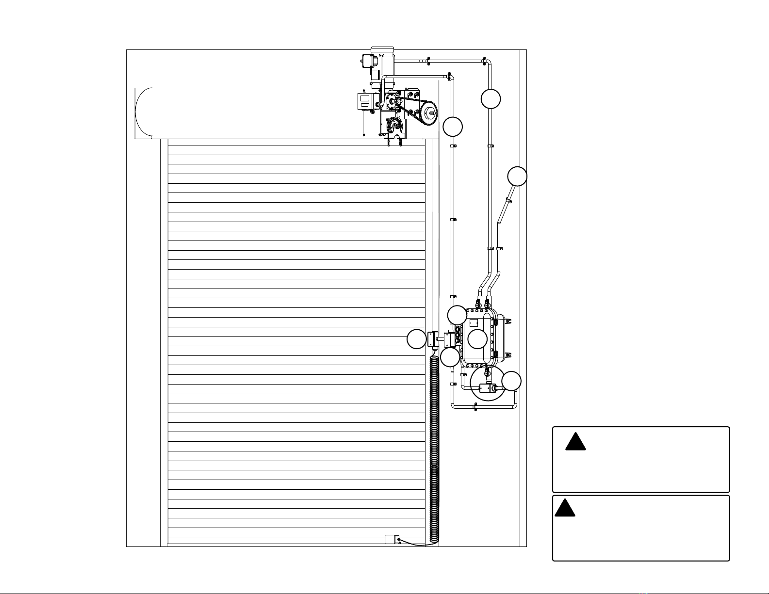
Overhead Doors are large, heavy objects that move with the help of springs under high tension
and electric motors. Since moving objects, springs under tension, and electric motors can cause
injury, your safety and the safety of others depend on you reading the information in this manual. If
you have any questions or do not understand the information presented, call your nearest service
representative. For the number of your local Overhead Door Dealer, call 800-929-3667, and for
Overhead Door Factory Technical Advice, call 800-275-6187.
In this manual the words Danger, Warning, and Caution are used to stress important safety
information. The word:
DANGER indicates an imminently hazardous situation which, if not avoided, will result in
death or serious injury.
WARNING indicates a potentially hazardous situation which, if not avoided, could result in
death or serious injury.
CAUTION indicates potentially hazardous situation which, if not avoided, may result in injury
or property damage.
The word NOTE,is used to indicate important steps to be followed or important considerations.
!
!
!
IMPORTANT
READ PRIOR TO ANY DOOR OPERATION
1. Read manual and warnings carefully.
2. Keep the door in good working condition.
Periodically lubricate all moving parts of door.
3. If door has a sensing edge, check operations
monthly. Make any necessary repairs to keep it
functional.
4. AT LEAST twice a year, manually operate the
door by disconnecting it from the operator.
The Door should open and close freely. If it
does not, the door must be taken out of service
and a trained service representative must
correct the condition causing the malfunction.
5. The Operator Motor is protected against
overheating by an internal thermal protector.
If the motor protector is tripped, a trained
service technical may be needed to correct the
condition which caused the overheating. When
the motor has cooled, thermal protector will
automatically reset and normal operation can
be resumed.
6. In case of power failure, the door can be
operated manually by pulling the release cable
to disconnect the operator drive system.
7. Keep instructions in a prominent location near
the pushbutton.
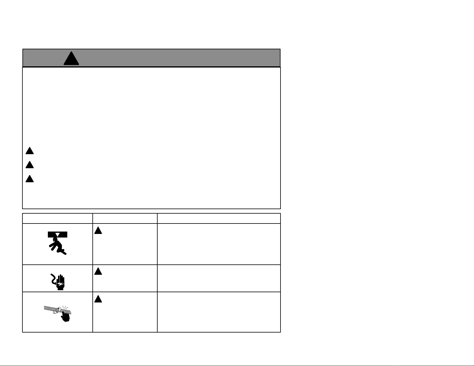
POTENTIAL HAZARD EFFECT PREVENTION
MOVING DOOR WARNING
Could result in Serious
Injury of Death
Do Not operate unless the doorway is in sight and free of
obstructions. Keep people clear of opening while door is moving.
Do Not allow children to play with the door operator.
Do Not change operator control to momentary contact unless and
external reversing means is installed.
Do Not operate a door that jambs or one that has a broken spring.
ELECTRICAL SHOCK WARNING
Could cause Serious
Injury or Death
Turn o electrical poser before removing operator cover.
When replacing the cover, make sure wires are not pinched or near
moving parts.
Operator must be electrically grounded.
HIGH SPRING TENSION WARNING
Could cause Serious
Injury or Death
Do Not try to remove, repair or adjust springs or anything to which
door spring parts are fastened, such as wood block, steel bracket,
cable or any other structure or like item.
Repairs and adjustments must be made by trained service
representative using proper tools and instructions.
!
!
!

2.2
Les portes basculantes sont de gros objets lourds qui fonctionnent à l’aide de ressorts soumis à une
haute tension et de moteurs électriques. Dans la mesure où les objets en mouvement, les ressorts
sous tension et les moteurs électriques peuvent entraîner des blessures, votre sécurité et celle des
autres exigent que vous preniez connaissance des informations stipulées dans ce manuel. Si vous
avez des questions ou si vous ne comprenez pas les informations ci-incluses, veuillez contacter le
représentant de service le plus près. Pour obtenir le numéro du revendeur Overhead Door local,
appelez le +1 (800) 929-3667, et pour obtenir des conseils techniques de l’usine Overhead Door,
appelez le +1 (800) -275-6187.
Dans ce manuel, les mots Danger, Avertissement, et Attention sont utilisés pour faire ressortir
d’importantes informations relatives à la sécurité. Le mot :
DANGER signale une situation dangereuse imminente qui si elle n’est pas évitée, risque d’entraîner
des blessures graves, voire mortelles.
AVERTISSEMENT signale une situation potentiellement dangereuse qui, si elle n’est pas évitée, risque
d’entraîner la mort ou des blessures graves.
ATTENTION signale une situation potentiellement dangereuse qui, si elle n’est pas évitée, risque
d’entraîner des blessures ou des dommages matériels.
Le terme REMARQUE est utilisé pour signaler les étapes importantes à suivre ou d’importants éléments
à prendre en considération.
AVERTISSEMENT
!
!
!
!
DANGER POTENTIEL EFFET PRÉVENTION
PORTE EN MOUVEMENT AVERTISSEMENT
Pourrait entraîner des
blessures graves voire la mort
Utiliser uniquement si la porte est en vue et libre de tout obstacle.
Ne laisser personne se tenir dans l’ouverture de la porte pendant
qu’elle est en mouvement.
Ne pas permettre aux enfants de jouer avec l’opérateur de la porte.
Ne pas modier la commande de l’opérateur à contact momentané
à moins qu’un moyen d’inversion externe soit installé.
Ne pas faire fonctionner une porte qui bloque ou dont le ressort
est cassé.
CHOC ÉLECTRIQUE AVERTISSEMENT
Pourrait entraîner des
blessures graves voire la mort
Couper le courant avant d’enlever le couvercle de l’opérateur.
Lorsque le couvercle doit être remplacé, s’assurer que les ls ne sont
ni coincés ni près des pièces mobiles.
L’opérateur doit être correctement mis à la terre.
TENSION ÉLEVÉE RESSORT AVERTISSEMENT
Pourrait entraîner des
blessures graves voire la mort
Ne pas essayer d’enlever, réparer ni ajuster les ressorts ou
toute autre pièce à laquelle le ressort de la porte est attaché, y
compris blocs de bois, supports en acier, câbles ou autres articles
semblables.
Les réparations et les réglages doivent être eectués par
technicien qualié qui se sert d’outils appropriés et qui respecte les
instructions.
!
!
!
Section 2: Safety Information and Instructions

3.1
Section 3: Critical Installation Information
WARNING: DO NOT apply line voltage until instructed to do so.
AVERTISSEMENT: NE PAS mettre sous tension tant que l’instruction n’est pas donnée de le faire.
!
!
ENTRAPMENT PROTECTION
The installation of a monitored external reversing edge is required on all momentary contact electronically operated commercial doors. If such a reversing device is not
installed, the operator will revert to a constant contact control switch for operation (Closing only).
The Reversing Devices currently UL Approved are:
1). MillerEdge® ME T2 and MT T2 Series monitored edge sensors.
!
Job Site Issues to Consider/Concerns
The following list of items should be considered prior to selecting an operator for a given job site.
1-Available power supply. 2-Type of door. 3-Potential operator mounting obstructions. Reversal of Limit Box (4.18). Items to consider include, but are not limited to: side room,
room above door shaft, room below door shaft, available mounting surface integrity, power supply location, and convenient chain hoist and release cable positioning. 4-Size
of door for appropriate operator torque and door travel speed selection. 5-Door activation needs/requirements. Examples include 3 button control stations, 1 button control
stations, pull cords, key switches. 7-Interlock switches are required under certain conditions for doors with pass doors and door locks. See Section 5.7. 8-Accessory equipment.
Examples include reversing edges which are required for doors set to operate as momentary contact, etc. See“Entrapment Protection”section below.

3.2
Section 3: Critical Installation Information
!
!
CAUTION: Check working condition of door before installing the operator. Door must be free from sticking and binding. If equipped, deactivate any door
locking device(s). Door repairs and adjustments, including cables and spring assemblies MUST be made by a trained service representative using proper tools and
instructions.
ATTENTION:Vériez l’état de fonctionnement de la porte avant d’installer l’opérateur. La porte doit pouvoir bouger librement et ne pas coincer. Désactivez
tous les dispositifs de verrouillage de la porte (si équipés). Les réparations et les réglages de porte, plus particulièrement pour les câbles et les ressorts DOIVENT
être eectués par un technicien qualié qui se sert d’outils appropriés et qui respecte les instructions.
IMPORTANT
INSTALLATION INSTRUCTIONS
WARNING
To reduce the risk of severe
injury or death:
1. READ AND FOLLOW ALL INSTALLATION INSTRUCTIONS.
2. Install only on a properly operating and balanced door. A door
that is operating improperly could cause severe injury. Have
qualied service personnel make repairs to cables, spring
assemblies and other hardware before installing the operator.
3. Remove all pull ropes and remove, or make inoperative, all
locks (unless mechanically and/or electronically interlocked
to the power unit) that are connected to the door before
installing the operator.
4. Install the door operator at least 8 feet above the oor if the
operator has exposed moving parts.
5. Do not connect the door operator to the power source until
instructed to do so.
6. Locate the control station: (a) within sight of the door, (b)
a minimum of 5 feet above the oor so that small children
cannot reach it, and (c) away from all moving parts of the
door.
7. Install the Entrapment Warning Placard next to the control
station and in a prominent location.
8. For products having a manual release, instruct the end user on
the operation of the manual release.
AVERTISSEMENT
Pour réduire les risques de
blessures graves ou de mort :
1. LIRE ET RESPECTER TOUTES LES INSTRUCTIONS D’INSTALLATION.
2. Installez uniquement sur une porte fonctionnant correctement
et bien équilibrée. Une porte qui fonctionne mal peut
provoquer des blessures graves. Demandez à un technicien
qualié d’eectuer les réparations des câbles, des ressorts et de
toute autre quincaillerie avant de procéder à l’installation de
l’opérateur.
3. Retirez toutes les cordes de traction ainsi que tous les verrous ou
rendez-les inopérants (à moins qu’ils ne soient mécaniquement
et/ou électroniquement interverrouillés à l’unité motrices) qui
sont connectés à la porte avant de procéderà l’installation de
l’opérateur.
4. Installez l’opérateur de la porte à 2,4 m minimum au-dessus du
sol lorsque des pièces mobiles de l’opérateur sont exposées.
5. Ne pas raccorder l’opérateur de la porte à la source d’alimentation
avant que l’instruction ne soit donnée de le faire.
6. Installez la station de commande : (a) en vue de la porte, (b) à
1,5 m minimum au-dessus du sol pour que les jeunes enfants
ne puissent pas l’atteindre, et (c) à l’écart de toutes les pièces
mobiles de la porte.
7. Installez le poster d’avertissement de pincement à côté de la
station de commande à un endroit bien en vue.
8. Pour les produits ayant un déclenchement manuel, indiquez à
l’utilisateur comment déclencher manuellement.
IMPORTANT
INSTRUCTIONS D’INSTALLATION

3.3
1) READ AND FOLLOW ALL INSTRUCTIONS.
2) Never let children operate or play with door controls. Keep the
remote control (where provided) away from children.
3) Personnel should keep away from a door in motion and keep the moving door
in sight until it is completely closed or opened. NO ONE SHOULD CROSS THE
PATH OF A MOVING DOOR.
4) Test the door’s safety features at least once a month. After adjusting either the
force or the limit of travel, retest the door operator’s safety features. Failure to
adjust the operator properly may cause severe injury or death.
5) For products having a manual release, if possible, use the manual release only
when the door is closed. Use caution when operating the release while the door
is open. Weak or broken springs may cause the door to fall rapidly, causing
severe injury or death.
6) KEEP DOOR PROPERLY OPERATING AND BALANCED. See Door Manufacturer’s
Owner’s Manual. An improperly operating or improperly balanced door could
cause severe injury or death. Have only trained door systems technicians make
repairs to cables, spring assemblies, other hardware and any wooden blocks
or like items to which they may be attached.
IMPORTANT
SAFETY INSTRUCTIONS
WARNING-
To reduce the risk of severe
injury or death:
7) SAVE THESE INSTRUCTIONS.
1) LIRE ET RESPECTER TOUTES LES INSTRUCTIONS.
2) Ne jamais permettre aux enfants d’actionner ni de jouer avec les commandes de la porte.
Tenir les télécommandes (si fournies) hors de la portée des enfants.
3) Le personnel doit se tenir à l'écart d'une porte en mouvement et garder bien en vue une porte en mouvement
jusqu'à ce qu'elle soit complètement fermée ou ouverte. PERSONNE NE DOIT TRAVERSER LA TRAJECTOIRE
D'UNE PORTE EN MOUVEMENT.
4) Testez les fonctionnalités de sécurité de la porte au moins une fois par mois. Après avoir réglé
la force ou la limite de la course, retestez les éléments de sécurité de l’opérateur de la porte. Un mauvais réglage
de l’ouvre-porte peut entraîner des blessures graves voire la mort.
5) Pour les produits ayant un déclenchement manuel, dans la mesure du possible, utilisez le déclenchement manuel
uniquement lorsque la porte est fermée. Prenez toutes les précautions nécessaires lors de l'utilisation du
déclenchement manuel alors que la porte est ouverte. Des ressorts faibles ou brisés peuvent faire descendre
la porte rapidement ce qui peut entraîner des blessures graves voire la mort.
6) VEILLER À CE QUE LA PORTE SOIT CORRECTEMENT ÉQUILIBRÉE ET FONCTIONNE BIEN. Consultez le manuel de
l’utilisateur du fabricant de la porte. Une porte déséquilibrée ou fonctionnant incorrectement pourrait entraîner
de graves blessures voire la mort. Seuls des techniciens formés sur systèmes de portes peuvent effectuer des
réparations aux câbles, aux ressorts, aux autres matériels et aux blocs de bois ou éléments
semblables auxquels ces éléments peuvent être attachés.
7) CONSERVER CES CONSIGNES.
CONSIGNES
DE SÉCURITÉIMPORTANTES
AVERTISSEMENT-
Pour réduire les risques de
blessures graves ou de mort :
Section 3: Critical Installation Information

3.4
Section 3: Critical Installation Information
Counter Doors
600610640/641650/651/652670671
Coilaway24GA. 22GA. 20GA. 18GA. 24GA. 22GA. 20GA. 18GA. 24GA. 22GA. 20GA. 18GA. 22GA. 22GA. / Alum Alum Steel
RHX®1/2 256*465403351268247215199169172** 168** 351** 268** N/A ALL*540240
RHX®1256*690600523399367320297252172** 168** 480** 399** N/A ALL*700340
RHX®3256* N/A 1137945867798696645548172** 168** 576** 696** N/A ALL*1080888
Rolling Fire Doors / Fire Shutters
630/631/634
610/620
Note: Door chart represents max. door height of 24ft., over 24ft high consult factory.
*Operator must be wall mounted.
RHX®Rolling Steel Door Chart (Sq. Ft.)
Grilles
Rolling Steel Doors
625
Model HP
416418420422424426430432591592593594596598599
Mounting
Type
Max. Door
Weight
(Lbs)
16GA.
Flush
Steel
16GA.
Flush
Steel
Insulated
20GA.
Ribbed
Steel
20GA.
Ribbed
Steel
Insulated
24GA.
Ribbed
Steel
24GA.
Ribbed
Steel
Insulated
Nominal
24GA.
Ribbed
Steel
Nominal
24GA.
Ribbed
Steel
Insulated
Ribbed
Steel
1 5/8"
Ribbed
Steel 2"
Ribbed
Steel
1 3/8"
Raised
Panel
Steel
1 3/8"
20GA.
Flush
Steel
1 5/8"
Ribbed
Steel
1"
Flush
Steel 2"
RHX®1/2 SC 1310330262406330448366326326490448326326380 200448326406
RHX®1SC 1650448366536448632490326326632584326326501 200448326526
RHX®
14 RPM -
Direct
Couple
Kit
1SC 2400490406684536792584326326792736326326632200448326526
RHX®
14 RPM -
Direct
Couple
Kit
3SC 36967015881020821102082132632611641020326326888200448326526
S= Jackshaft, Side Mount, C= Jackshaft, Center Mount
NOTE: Side/Center direct couple kit output speed is 26RPM for 1/2 and 1 HP. For larger doors use 14 RPM output speed direct couple kit on 1HP and 3HP RHX®operators.
NOTE: Total door weight, and not the square footage, is the critical factor in selecting the proper operator. Square foot measurments are based on "Square Doors". (Example = 16' X 16')
NOTE: Doors that require special wind loading and wide doors normally require strutting(reinforcement). Strutting doors can signicantly increase door weight beyond maximum weight shown. Consult factory
RHX®Sectional Door Chart (Sq. Ft.)
Model HP
Commercial Steel Insulated & Non-Insulated
Thermacore
Aluminum
Door Series ->
511521
HOIST
416418420422424426430432591592593594596598599
Max. Door
Weight
(Lbs)
16GA.
Flush
Steel
16GA.
Flush
Steel
Insulated
20GA.
Ribbed
Steel
20GA.
Ribbed
Steel
Insulated
24GA.
Ribbed
Steel
24GA.
Ribbed
Steel
Insulated
Nominal
24GA.
Ribbed
Steel
Nominal
24GA.
Ribbed
Steel
Insulated
Ribbed
Steel
1 5/8"
Ribbed
Steel 2"
Ribbed
Steel
1 3/8"
Raised
Panel
Steel
1 3/8"
20GA.
Flush
Steel
1 5/8"
Ribbed
Steel
1"
Flush
Steel 2"
RHX®1/2 1310330262406330448366326326490448326326380 200448326406
RHX®11650448366536448632490326326632584326326501200448326526
NOTE: Total door weight, and not the square footage, is the critical factor in selecting the proper operator. Square foot measurments are based on "Square Doors". (Example = 16' X 16')
NOTE: Doors that require special wind loading and wide doors normally require strutting(reinforcement). Strutting doors can signicantly increase door weight beyond maximum weight shown. Consult factory
RHX®Trolley Sectional Door Chart (Sq. Ft.)
Model HP
Commercial Steel Insulated & Non-Insulated
Thermacore
Aluminum
511521

4.1
1) Determine operator mounting location, including desired
hoist and release location and release cable routing.
2) Weld the Rolling Door weld plate assembly to the door
headplate, a minimum of two 1”weld beads are required on
each side of the weld plate for proper attachment. See Fig 1
for proper placement.
REFER TO SHOP DRAWINGS FOR
SPECIFIC DIMENSIONING INFORMATION
Rolling Steel - Front of Hood & Top of Hood Mount Weld Plate Attachment
Section 4: Installation - Hoist
HP REQUIRED MOUNTING KIT PART NUMBER
1/2, 1 ROLLING STEEL - FOH-TOH OPMKRSHX.S
3 ROLLING STEEL - FOH-TOH OPMKRSHX3HP.S
Figure 1 WELD PLATE ATTACHMENT
9”
P/N 110010.0001.S P/N 110010.0001.S
WELD TO HEADPLATE. WELD TO HEADPLATE.
“A”
MIN. (2) 1/4”X 1”WELD
1/4” MIN. (2) 1/4” X 1”WELD
DIM
BEADS ON EACH SIDE BEADS ON EACH SIDE
OF BRACKET. OF BRACKET.
1/4”
1/4”
“A”DIM “A” DIM
HEADPLATE (1/2-1 HP)SIZE (3 HP)
WELD BEADS TO -
BE ALONG THIS -
EDGE ON BACK
SIDE OF BRACKET 6 1/8”18” -
(IF BRACKET EXTENDS 7 1/8 ”
20”
BEYOND HEADPLATE)
9 1/4”
22” 9 1/4”
24”& LARGER
FRONT OF HOOD TOP OF HOOD
HEAD PLATE DETAIL HEAD PLATE DETAIL
(STANDARD WELD BRACKET LOCATION) (18” or larger 1/2-1hp, 24” for 3hp)
(STANDARD WELD BRACKET LOCATION)
(14”HEADPLATE & LARGER)
-
-
14” 4 1/8”
16”FPH only 5 1/8”
FOH only
NOTE: If installation will require the reversal of the limit box, refer to
page 4.18

4.2
Figure 3
Section 4: Installation - Hoist
Figure 2
3/8”-16 X 1-1/2” Bolts, nuts,
lockwashers (SEE NOTE)
7/16”-14 Hex Nuts
Washers
FRONT OF HOOD MOUNT TOP OF HOOD MOUNT
1) Attach operator to main mounting bracket using the four
3/8”-16 x 1-1/2”bolts, hex nuts, and lock washers. See Fig 2.
NOTE: For 3 HP units, 1/2”-13 x 2-1/2”bolts are required.
2) Mount the operator to the weld plate using the 7/16”-14 hex
nuts. Hand tighten bracket to weld plate nuts.
Attach Operator to Door: Fig. 3.
3) Attach 12 tooth sprocket to operator output shaft.
4) Align keyways and insert key into sprocket and output shaft
keyway. Do not tighten set screw at this time.
5) Attach door sprocket to door shaft. Align keyway and insert
key. Do not tighten set screws at this time.
6) Assemble chain using chain master link.
7) Place assembled chain over door shaft sprocket and around
the 12 tooth sprocket and align.
8) Raise or lower operator to remove slack from the chain. Be
certain operator output shaft is parallel with door shaft.
9) While applying tension to chain, tighten operator mounting
bracket nuts.
10) Tighten sprocket set screws.
11) Proceed to page 4.7
REFER TO SHOP DRAWINGS FOR
SPECIFIC DIMENSIONING INFORMATION
Rolling Steel - Front of Hood & Top of Hood Mount
The RHX® Rolling Steel Operators are factory assembled for right-
hand mounting (shown). Each model can also be converted to
left-hand mount See page 4.7 for instructions.

4.3
1) Determine operator mounting location, including desired
hoist and release location and release cable routing.
2) Weld the Rolling Door weld plate assembly to the door
headplate, a minimum of two 1”weld beads are required on
each side of the weld plate for proper attachment. See Fig. 4
for proper placement.
3) Attach operator to main mounting bracket using the four
3/8”-16 X 1-1/2”bolts, hex nuts, and lock washers. (For 3HP
use 1/2”-13 x 2 1/2”bolts)
Rolling Steel - Bench Mount
4) Mount the operator to the weld plate using the 7/16”-18 hex
nuts. Hand tighten bracket to weld plate nuts.
5) Attach 12 tooth sprocket to operator output shaft.
6) Align keyways and insert key into sprocket and output shaft
keyways. DO NOT tighten set screw yet.
7) Attach door sprocket to door shaft. Align keyway and insert key.
DO NOT tighten set screw yet.
8) Assemble chain using master link.
9) With mounting bolts/nuts loosened, shift the position of the
operator in order to remove slack from the chain.
10) While applying tension, fully tighten mounting bolts/nuts.
11) Tighten sprocket set screws.
12) Proceed to page 4.7
Figure 4 BENCH MOUNTING
1/4” WELD TO
HEADPLATE
8”
MIN.
Bench Mount Bracket
P/N 111791.0001
Section 4: Installation - Hoist
HP REQUIRED MOUNTING KIT PART NUMBER
1/2, 1 ROLLING STEEL - BENCH MOUNT OPMKRSBMHX.S
3 ROLLING STEEL - BENCH MOUNT OPMKRSBMHX3HP.S
The RHX® Rolling Steel Operators are factory assembled for right-
hand mounting (shown). Each model can also be converted to
left-hand mount See page 4.7 for instructions.
* This style of installation may require 90 deg. elbow
tting or reversal of limit switch assembly. See page 4.18
*

4.4
1) Attach optional wall mount bracket to operator (if needed)
using the 4 mounting bolts and nuts supplied. Fully tighten.
Position the operator with the bracket as shown.
2) Attach 12 tooth sprocket to operator output shaft.
3) Align keyways and insert key into sprocket and output shaft
keyway. Do not tighten set screw at this time.
4) Attach door sprocket to door shaft. Align keyway and insert
key. Do not tighten set screw at this time.
5) Assemble chain using chain master link.
6) Position operator near door shaft with sprockets
aligned.
7) Place assembled chain over door and operator
sprockets.
8) Lift or lower the operator as needed to tension
drive chain.
9) Secure operator to wall.
• You MUST use the LOCK DOWN HOLES (at
least 2) to prevent the unit from becoming
misaligned during operation. Fig. 5.
10) Check vertical alignment of the drive chain/
sprockets and tighten sprocket set screws.
11) Proceed to page 4.7.
Rolling Steel - Wall Mount & Sectional Side Mount
Section 4: Installation - Hoist
HP REQUIRED MOUNTING KIT PART NUMBER
1/2, 1 WALL MOUNT OPMKWMHX.S
3 WALL MOUNT OPMKWMHX3HP.S
Figure 6 ROLLING STEEL
Figure 7 SECTIONAL
LOCK DOWN HOLES (4)
Figure 5
WALL MOUNT
BRACKET
The RHX® Hoist Operators are factory assembled for right-hand
mounting (shown). Each model can also be converted to left-
hand mount See page 4.7 for instructions.

4.5
NOTES:
1) A clearance of 8”should be allowed for access to all electric connections.
2) Average door travel speed varies per drum used.
3) Operator mounting brackets mount to wall.
Sectional Doors - Direct Couple (Right hand unit shown)
Refer to Direct Couple Supplemental Instruction ( Included with Direct Couple Kit)
SIDEMOUNT 14 RPM DIRECT COUPLE SIDEMOUNT 26 RPM DIRECT COUPLE
Figure 8
Section 4: Installation - Hoist
HP REQUIRED MOUNTING KIT PART NUMBER
1/2, 1 DIRECT COUPLE - 26RPM OPMKDC26HX.S
1/2, 1 DIRECT COUPLE - 14RPM OPMKDC14HX.S
3 DIRECT COUPLE - 14RPM OPMKDC14HX3HP.S
The RHX® Hoist Operators are factory assembled for right-hand
mounting (shown). Each model can also be converted to left-
hand mount See page 4.7 for instructions.

4.6
Sectional Doors - Center Mount Direct Couple (Right hand unit shown)
NOTES:
1) A clearance of 8”should be allowed for access to all electric
connections.
2) Average door travel speed varies per drum used.
3) Operator mounting brackets mount to wall.
Refer to Center Mount Supplemental Instruction, ( Included with Center Mount Kit)
14 RPM UNIT SHOWN
VERTICAL CENTER MOUNT HORIZONTAL CENTER MOUNT
HP REQUIRED MOUNTING KIT PART NUMBER
1/2, 1 CENTER MOUNT VERTICAL OPMKCMVHX.S
1/2, 1 CENTER MOUNT HORIZONTAL OPMKCMHHX.S
3CENTER MOUNT VERTICAL OPMKCMVHX3HP.S
3 CENTER MOUNT HORIZONTAL OPMKCMHHX3HP.S
SUPPORT REQUIRED
(NOT PROVIDED)
SUPPORT REQUIRED
(NOT PROVIDED)
Figure 9 Figure 10
Section 4: Installation - Hoist
The RHX® Hoist Operators are factory assembled for right-hand
mounting (shown). Each model can also be converted to left-
hand mount See page 4.7 for instructions.
Refer to Direct Couple Supplemental Instruction, ( Included with Direct Couple Kit)
HP REQUIRED MOUNTING KIT PART NUMBER
1/2, 1 DIRECT COUPLE - 26RPM OPMKDC26HX.S
1/2, 1 DIRECT COUPLE - 14RPM OPMKDC14HX.S
3 DIRECT COUPLE - 14RPM OPMKDC14HX3HP.S

4.7
Unpacking and Conguring Release Cord: Fig. 11
1) The cord comes shipped connected to the Release Lever and
looped around the end of the hoist shaft opposite the handwheel,
with the bulk of the cord taped to the handwheel side of the
brake enclosure (SIDE A).
2) Un-tape the bulk of the cord from the side panel of brake
enclosure.
3) Straighten cord , ensuring there are no kinks or knots.
4) Determine which side you want the cord to be on.
5) For use on SIDE A, un-loop cord from the SIDE B end of hoist
shaft and pull it out through SIDE A hole.
6) For use on SIDE B, pull cord out through SIDE B hole.
Shifting Manual Handwheel SIDE A to SIDE B: Fig. 11
1) Loosen the set screws (1) and remove set collar (2).
2) Slide the chain guard (3) and handwheel (4) o of hoist shaft.
3) Slide all onto opposite side in order shown and tighten set screws.
Handwheel, Chain and Keeper
1) Route the hand chain through the chain guide, around the pocket
wheel and back through the chain guide. Fig.12.
2) Connect the hand chain ends together as shown in Fig 13. by
twisting open the last link on one end of the chain, and slipping
the last link on the opposite end onto the open link.
3) Twist open link closed again.
4) Mount chain keeper to wall in line with chain approximately 4 feet
from oor.
5) Loop chain around keeper as shown. Fig. 14. Optional Padlock
not provided.
NOTE: To insure smooth operation, make sure there is no twist in the
hand chain before connecting the link ends together.
SIDE B SIDE A
4
1 2
3
Section 4: Installation - Hoist
Cover removed for illustration. Removal of cover is not necessary.
UN-LOOP cord from shaft

4.8
NOTE: The clutch is intended to provide protection for the door,
operator and associated equipment.
It is not intended for entrapment protection.
The RHX® Clutch does not require any disassembly to adjust.
1) All adjustments should be made in very small increments
(e.g. turning adjustment bolts 1/4 turn per increment).
2) When making adjustments, be sure to turn all 3 adjustment
bolts an equal amount. Fig 15.
- To increase tension, turn adjustment bolts clockwise.
- To decrease tension, turn adjustment bolts counter-
clockwise.
3) Clutch needs to be adjusted to a tension just above what is
required to open and close door without clutch slippage.
NOTE: Periodically check the system for proper clutch action.
If clutch starts to slip after working properly for some time,
check manual operation of door before adjusting clutch. Door
may not be operating freely or counter-balance spring may
need adjusting. Repairs and adjustments must be performed
by a trained service representative using proper tools and
instructions.
Adjusting the Clutch (Optional) P/N 111817.0002 1/2 & 1HP Only
ADJUSTMENT
BOLTS
Section 4: Installation - Hoist
Installing Vent Plug
NOTE: The vent plug is to prevent over-pressurization of the
gearbox and must be installed to prevent leakage at the seals.
The RHX® Includes the vent plug taped to the gear box.
1) Remove uppermost plug from gearbox dependent on how
the unit is mounted.
2) Location A for motor up or TOH and bench mount positions.
3) Location B for motor down positions.
4) Install vent plug in its place.
A
B
Parts removed for clarity

4.9
Section 4: Installation - Trolley
Trolley Models
A
BC
D
EF
G
H
Figure 1
NOTE: Drawbar tracks must be (29) inches longer than the door’s
height. Tracks have been sized properly and pre-punched for the chain
guide assemblies from the factory.
7/16-14 HEX HEAD
BOLTS, LOCK WSHR’S
& HEX NUTS
Figure 2
Trolley units are also available in Sidemount and
Dual Trolley versions.
HP Kit Part Number
1/2, 1 Sidemount Trolley Kit OPAKSMTHX.S
1/2,1 Dual Trolley Kit OPAKDTHX.S
Sidemount Trolley utilizes a HOIST operator in
combination with a Sidemount Trolley Kit.
The Model RHX® Trolley Operator consists of the:
Power Unit (A)
Drawbar Track (B)
Chain Guides (C)
Header Bracket (D)
Idler Pulley (E)
Drive Chain (F)
Drive Sprocket (G)
Drawbar Arm (H)
The Drawbar track length, chain length and quantity of chain guides
will vary by door heights. Fig. 1.
1) Attach Track to Power Unit using four (4) 7/16”-14 x 1”hex bolts,
7/16”-14 hex nuts and 7/16”lock washers (provided) Fig. 2.

4.10
Section 4: Installation - Trolley
Drawbar Assembly
CHAIN GUIDE BRACKET
TRACK BOLTS
/LOCKNUTS
PLASTIC CHAIN GUIDE
Figure 3
NOTE: Space chain guides evenly between operator and header. Add
a chain guide for every 4 feet of door height per chart.
2) Attach the chain guide assemblies to the drawbar tracks using
1/4-20 track bolts and locknuts (provided). Fig. 3.
CAUTION
Verify that bolts are properly seated in track. Failure to seat bolts
can cause carriage to bind in door track.
!
UNDER 12’ 12’TO 16’ 16’TO 20’ 20’TO 24’
2345
NOTE: Chain Guide mounting holes have been pre-drilled at standard
locations along the track. If dierent locations are needed, hole size
should be 9/32”dia. Be sure to de-burr the holes.
ATTENTION
Vériez que les boulons sont bien en place dans la piste. Si les
boulons sont mal logés, le chariot peut se coincer dans la piste de
la porte.
!
This manual suits for next models
1
Table of contents
Other Overhead door Door Opening System manuals