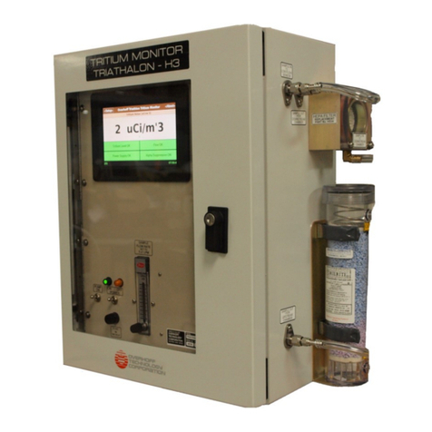
overhoff TASC-HTO-HT-C14 Manual

OPERATION/MAINTENANCE MANUAL
CARBON 14 AND TRITIUM
IN AIR SAMPLE COLLECTOR
MODEL TASC-HTO-HT-C14
27 April 2017
REV. 0
OVERHOFF TECHNOLOGY CORPORATION
1160 US ROUTE 50, MILFORD, OHIO, USA

UTABLE OF CONTENTS
USECTIONUUPAGE
1.0. INTRODUCTION 1
2.0. SPECIFICATIONS 2
3.0. OPERATION 3
4.0. USE OF INSTRUMENT 5
5.0. SERVICE 8
6.0. ANALYSIS 9
7.0. MISCELLANEOUS INFORMATION 13
8.0. WARRANTY 14
9.0. REPLACEMENT PARTS LIST 15
APPENDIX
FIGURE 1, CARBON 14 ANALYSIS SET-UP
DRAWING, TASC-HTO-HT-C14, FRONT & REAR PANEL
DRAWING, TASC-HTO-HT-C14 AND SEPARATE C14 COLLECTION PANEL
DRAWING, TASC-HTO-HT-C14, BLOCK DIAGRAM
DRAWING, TASC-HTO-HT-C14, FLOW DIAGRAM, TRITIUM AND C14 COLLECTION
DRAWING, TASC-HTO-HT-C14, FLOW DIAGRAM, TRITIUM ONLY COLLECTION
DRAWING, TASC-HTO-HT-C14, WIRING DIAGRAM
MANUFACTURERS DATA SHEETS
MATERIAL SAFETY DATA SHEET, DESICCANT
MATERIAL SAFETY DATA SHEET, ASCARITE

1
1.0. INTRODUCTION
1.1. GENERAL DESCRIPTION
Overhoff Technology Corporation’s (OTC) Tritium and Carbon 14 in air sampler (TASC)
is a simple and reliable line powered device for the passive sampling of very low levels of
Carbon 14 and of tritium.
This unit uses conventional techniques for collecting samples for any suitable length of
time, as preferred by the user.
Tritium, in both elemental and oxide forms is collected in water or glycol filled vials, hence
the popular description of “bubbler” is applied to these instruments.
Carbon 14 can be trapped in NaOH or KOH solutions, or on solid pellets as dispensed
under the trade name of Ascarite.
The TASC series of instruments can be used in buildings or out of doors when suitably
protected. Limits of sensitivity are typically of the order of 1 x 10⁻⁹ μCi/cc for tritium,
1 x 10-11 μCi/cc for Carbon 14.
A regulated thermal oxidizer converts elemental tritium into its oxide form to permit
separate measurement of tritium in both its oxide and elemental form.
Analyses of the collected radioactive material is performed separately by conventional
scintillation counting techniques.

2
2.0. SPECIFICATIONS -
3H/14C SAMPLER
Sensitivity: For 3H: 1 x 10⁻⁹ μCi/cc for 7 day sample at 100±3 scc/min
For
14C: 1 x 10-11 μCi/cc for 7 day sample at 100±3 scc/min
Air Flow Rate: 100±3 scc/min factory calibrated set point
Flow Meter: Mass flow meter, 250 scc/minute full scale
Air Flow Indicator: scc/min, Digital Display, 3½-digits, 0.1 to 199.9
Air Mover: Continuous duty, diaphragm pump
Elapsed Time Indicator: Multifunction timer module, with maximum time setting of
0.1 to 999.9 hours, with programmable reset
Thermal Oxidizer: Regulated air heater, range: 455° - 475°C (851° - 887°F)
Temperature Indicator: °C, Digital Display, 3½-digits, 1 to 1999
Unit Cooling: Continuous duty fan; 30 CFM free flow
Sample Collectors: Two manifolds made from a silver-brazed construction of
stainless steel and brass, nickel electroplated. Three
polyethylene vials, 20 ml volume each mount onto each
manifold for HTO and HT, total of six vials
Power Connection: 2.5 meters long, detachable EURO grounded cord
Power Requirements: 220-240 VAC, 50-60 Hz, 1 Ph, 200 Watts
Overall Dimensions: 14” [550mm] D x 19” [750mm] W x 12.2” [480mm] H
Weight: 30 pounds, 13.6 Kgs
Sample Connections: Inlet/Exhaust: Hose barb for 3/16” I.D. tubing
Carbon 14 Collection
Desiccant: Up to 4 drying columns containing indicating Drierite™
Sample Collector: 15cc polycarbonate tube filled with Ascarite™20 – 30 mesh
Overall Dimensions: 5.25” [207mm] D x 19” [750mm] W x 16.25” [640mm] H
Weight: 20 pounds, 9.1 Kgs
Connectors: Hose barbs for 3/16” I.D. vinyl tubing

3
3.0. OPERATING PRINCIPLES
3.1. SAMPLE COLLECTION
The OTC TASC Sampling System operates by trapping radioactive material in vials
containing absorbent material.
To ensure virtually total collection, each main vial is succeeded by a second and third vial
whose purpose is to trap any of the material which was missed by its predecessor.
Six vials are therefore used to trap tritium oxide and elemental tritium.
For the collection of tritium, the vials are either filled with clean water or glycol, or they
may be packed with a water absorbing medium such as drierite™ or molecular sieve.
The solid materials are available with color indicators to signal saturation.
In practice, the sampled air is first filtered for dust, then passes directly through the first
three vials where the tritium oxide is collected. The sample air is then treated in the tube
furnace where elemental tritium and carbon fractions are oxidized. The tritium oxide is
collected in the next three vials, and the carbon 14 fraction is trapped in the Ascarite
cartridge, where the carbon dioxide is converted to sodium (potassium) carbonate.
The remnant air stream passes through the flow moving system, which consists of the
mass flow meter, the flow controller circuit board and the pump.
The mass flow rate is adjusted at the factory to 100±3 scc/min, and is set by a
potentiometer associated with the flow controller circuit board.
3.2. FRONT PANEL FEATURES
IMPORTANT: If the flow meter display does not indicate airflow of 100±3 scc/min, the
seating of the vials should be checked. Loose seating of the vials will
permit leaks in the sample flow.
The following features are found on the front face of the instrument.
1. INLET and OUTLET hose barbs for plastic tubing.
2. A dust filter which can be readily exchanged when observed to be dirty.
3. The digital mass flow rate indicator, 100±3 scc/min is internally set for 20 ml vials
4. The temperature indicator for the regulated thermal oxidizer, 455° - 475°C (851° - 887°F)
5. The collecting vials, six for tritium.
6. Timer module.
7. POWER toggle switch.
8. START locking toggle switch.
9. Low Flow Alarm visual indicator, red LED
10. Hose barbs for tubing connections to C14 Collection Panel

4
3.3. INTERNAL STRUCTURE
The enclosure contains the following internal components.
1. Cooling fan.
2. Thermal oxidizer inside insulated housing.
3. Temperature Controller for the thermal oxidizer.
4. The airflow control P.C. board assembly (factory set to 100±3 scc/min).
5. The pneumatic components; sampling pump, vacuum reservoirs, mass flow meter
and associated hoses.
6. Relief valve, solenoid controlled.
3.2. REAR PANEL FEATURES
IMPORTANT: The thermal oxidizer operates at 455° - 475°C (851° - 887°F), but for
safety the heat generated is well insulated from the outside surfaces of
the equipment. However, the lower middle area of the rear panel will be
warm and possibly hot to the touch.
The following features are found on the rear panel of the instrument.
1. AC mains power receptacle for detachable line cord.
2. AC mains fuse.
3. Intake grill with replaceable filter element for cooling fan.
4. Exhaust grill for cooling fan
3.3 CARBON 14 COLLECTION PANEL FEATURES
1. There are 4 drying columns containing indicating Drierite™, which is manufactured
by W.A. Hammond Drierite, Xenia, Ohio USA. The complete drying column is part
no. 26800. Replacement material in a 5 gal. glass jar is part no. 23005.
2. C14 Sample Collection tube, 15 cc volume polycarbonate tube to be filled with
Ascarite™20 – 30 mesh. Ascarite™was not shipped with the TASC unit because it
is classified as dangerous goods. It is available from most scientific/chemical
suppliers. Example: Sigma-Aldrich product no. 223921, Sodium Hydroxide 20-30
mesh, available quantity:100g or 500g, packed in a poly bottle.

5
4.0. USE OF INSTRUMENT
4.1. INSTALLATION AND SET-UP
1. Install the instrument in a readily accessible area, protected from accidental
damage, and from the elements if stationed out of doors.
2. Supply 230VAC ±10%, 50-60Hz power (200 watts max.) to the instrument.
3. Connect power and sampling tubing as required, ensure that the air sampling
inlet lines do not unduly restrict air movement (flow) by verifying that the mass
flow rate of 100±3 scc/minute is maintained at all times. It is normal in the first
few minutes after switching power ON, for the mass flow display to fluctuate
100±3 scc/minute.
4. Inspect the dust filter every two months and replace if dirty.
5. Fill the vials with absorbing medium, reagent material (see Section 6).
6. The main settings have been preset at the factory. The flow rate is set to 100±3
scc/min, the thermal oxidizer temperature set-point is 455° - 475°C (851° - 887°F).
The timer module can be configured in accordance with the manufacturer’s data
at the end of this manual.
7. Do not forget to reset the timer module whenever a new sample collection period
is started.
8. BEFORE Power-Up
a. Power toggle; down position (OFF)
b. Start Toggle; down position
c. Vials are fully seated
d. A logbook or some other preferred method should be used to record data
referring to measured results in terms of time and dates.
CAUTION: Do not unscrew a collecting vial while the pump is on. This could cause a sudden change
in pressure or vacuum in certain parts of the pneumatic system which could cause liquid
to be drawn from one of the other vials into the piping. Always make sure the pump is
turned off and bubbling has completely stopped before removing a collection vial.
IMPORTANT: In a worse case situation, where the sample air is very dry, the liquid level in the first
HTO vial should be expected to drop 3 - 10 cc over a seven day period. Also, it is
important not to overfill the vials, because bubbling over could occur, which would result
in liquid being trapped in the piping. It is recommended not to exceed 18 cc of liquid
when filling each vial. If it is observed that there is a loss liquid in the first HTO vial due
to evaporation, it is recommended that sample collecting is done over shorter period. For
extreme cases where the sample is very dry and must be collected over longer periods of
time, the system flow rate can be decreased. If the flow rate is adjusted then the manual
and the analysis calculation must be changed accordingly.
CAUTION: C14 collection medium is Acscarite™(sodium hydroxide). Use extreme care when
handling this material. Consult Material Safety Data Sheet (MSDS) at the end of the
manual.

6
4.2. OPERATING PROCEDURE
1. Power-up phase from a cold start:
a. POWER toggle; move to up position (ON)
Observe the following:
b. Oxidizer temperature and Mass Flow Meter displays illuminated.
c. Timer Module display is illuminated. The upper digit display is the current actual
value, press reset to clear this value. The lower digit display is the set point
value. Refer to the manufacturer’s data at the end of this manual for settings.
d. Sampling pump is not operating.
e. LOW FLOW Alarm is illuminated.
f. Mass flow meter display indicates ZERO flow rate. The vials are NOT bubbling.
Begin Warm-up phase:
g. START toggle; pull locking handle outward and lift to up position (START).
Observe the following:
h. Oxidizer temperature display begins to increase.
i. Timer Module display illuminates a DOT in the upper left corner of the display to
indicate that it is counting. The upper digit display is the current actual value.
The lower digit display is the set point value.
j. Sampling pump is operating continuously until mass flow meter display reaches
100±3 scc/min when it changes to intermittent duty mode as controlled by the
electronic mass flow controller.
k. LOW FLOW indicator is not illuminated when mass flow rate reaches 100±3
scc/min.
l. Mass Flow meter display indicates 100±3 scc/min. flow rate. The vials are
bubbling.
This verifies that the system is in working order and in the warm up phase.
2. Normal operating mode, observe the following:
a. Oxidizer temperature display is at the nominal operating temperature is 455° -
475°C (851° - 887°F).
b. Timer Module display illuminates a DOT in the upper left corner of the display to
indicate that it is counting. The upper digit display is the current actual value.
The lower digit display is the set point value.
c. Pump is operating in an intermittent duty mode as controlled by the electronic
flow controller.
d. LOW FLOW indicator is not illuminated.
e. Mass Flow meter display indicates 100±3 scc/min. flow rate. The vials are
bubbling.
NOTE: The oxidizer temperature display reading rises as the system warms-up to the nominal
operating temperature of 455° - 475°C (851° - 887°F). When the flow rate is stopped or
below specification due to a malfunction, the heating process will be interrupted. This will
be indicated by the low flow indicator light and the declining temperature readings
displayed on the temperature display. Check the mass flow meter display, it should
indicate 100±3 scc/min. Loss of flow can be caused at the vial connection on the
manifold due to loose fitting or a missing or damaged o-ring seal.

7
CAUTION: Do not unscrew a collecting vial while the pump is on. This could cause a sudden change
in pressure or vacuum in certain parts of the pneumatic system which could cause liquid
to be drawn from one of the other vials into the piping. Always make sure the pump is
turned off and bubbling has completely stopped before removing a collection vial.
4.3. IMPORTANT PRECAUTIONS FOR PASSIVE SAMPLER, MODEL TASC
The collection liquid can move accidentally into parts of the system where it should not
be. This is one thing that must be prevented, because the sample transport system is
designed only for moving air, not liquid. It is extremely important that the collection liquid
remain in the vials.
Take only the following precautions:
a. DO NOT TIP THE INSTRUMENT ON ITS SIDE WHENEVER THERE IS
COLLECTING LIQUID IN THE VIALS.
b. DO NOT TRANSPORT THE INSTRUMENT WITH COLLECTION LIQUID IN THE
VIALS.
c. DO NOT UNSCREW A VIAL WHILE THE PUMP IS RUNNING. Always make sure
the pump is off and bubbling has completely stopped before removing a collecting
vial. Wait two minutes after the pump has stopped.
d. If a hose is connected to the sample in hose barb, be certain that it does not get
plugged or pinched closed, this will be indicated by the LOW FLOW indicator light
on the front panel, and can cause a vacuum to form in the filter housing, thus
drawing liquid into it, if the pump is stopped. In this particular situation, it is very
important to RELIEVE THE VACUUM CONDITION BY REMOVING THE HOSE ON
THE SAMPLE IN HOSE BARB PRIOR TO SWITCHING THE INSTRUMENT PUMP
OFF.
e. The mass flow rate calibration can be verified with the vials empty or full of
collecting liquid. The mass flow display on the front panel of the TASC shall indicate
100±3 scc/min.
f. The liquid level first vial of the three in the HT section may increase. This is caused
by condensate from the oxidizer when heating up from a cold start. Adjust the liquid
level accordingly or run the system without liquid for the warm up phase.
g. The recommended collection medium for C14 is Acscarite™(sodium hydroxide). It
is very corrosive; refer to MSDS at the end of this manual. If there is moisture in the
sample passing through the Ascarite, it will react with it and cause it to partially
dissolve turning it into a paste-like consistency, at which point the sample flow will
be obstructed, and the collection system will cease to operate. Four desiccant
columns connected in series will assure complete removal of the moisture in the
sample prior to entering the C14 collection tube. This should be sufficient quantity of
material to last for the duration of a week long sampling period. Attach the
cartridges to the front of the separate C14 panel by means of plastic hose. The
sample air travels from your left to right when viewing the front panel of the TASC.
The sample air should first move through the drier cartridges, then through the
ASCARITE cartridge. Start the TASC pump and check the flow meter indication at
100±3 scc/min to ensure that the system is free from leaks. Now the TASC is ready to
begin another sample collection sequence. REMEMBER TO RESET THE TIMER.

8
5.0. SERVICE
Apart from the obvious periodic sample collection, which involves detaching the vials, no regular
service maintenance is required.
Periodic maintenance can be restricted to replacing the dust filter every two months (depending
on its condition).
The air sampling pump is a mechanical device, subject to wear. It can under optimum conditions,
last two years or more, but, sooner or later it will wear out and will need to be replaced.
The same applies to the cooling fan, although this unit will exhibit a longer life.

9
6.0. ANALYSIS
6.1. TRITIUM ANALYSIS
Analysis of the collected samples is carried out in a conventional manner, in the sense
that it is assumed that the collection efficiency is either very close to 100 %, or at least
reasonably well known.
The analysis is therefore based on the assumption that the activity of 100 cc of air is
accumulated every minute, thus, by reference to the observed lapsed time, it should be
possible to derive the average air concentration by measuring the contents of the vials
with a scintillation detector.
If liquid (water or glycol) collecting media is used, and the entire contents of the Wheaton
vials will fit into the scintillation counter (together with cocktail) (see Note A below)
Then the determination of activity is straight forward.
()
()( )
V
RR
Cbs
∈∗
−
=6
1022.2
Where
C = concentration of tritium in air in μCi/cc
Rs= counting rate of sample (cpm)
Rb= background count rate (cpm)
definition of Curie = 2.22 x 10¹² disintegrations per minute
∈= counting efficiency
V = volume of air in cc (product of flow rate in cc/minute times the
sampling duration in minutes)
NOTE A: If only parts of the vial contents are counted, then the value of C as
determined from the above ratio needs to be recalculated to take the
relative aliquot quantity into account. Thus, for example, if only half the
contents of the vial is actually counted, then the calculated value has to
be doubled to yield the true value of airborne concentration.

10
6.2. CARBON 14 ANALYSIS
The following procedure is used if Ascarite (solid NaOH with indicator) is used.
The analysis of the 14C concentration is obtained by acidification of the entire sample of
Ascarite media in a closed distillation system. Distillation releases CO2which is captured
downstream in a liquid scintillation cocktail in a countable form. The counting rate
obtained for the sample is converted to 14C concentration by dividing by counting
efficiency and the volume of air passed through the sampler. Testing has shown the
distillation yield to be 95 ±5 %.
EQUIPMENT REQUIREMENTS (See the schematic diagram in Figure 1)
Addition funnel with bubbler
Flask, two-hole reflux with ground glass joints, 1000 ml
Heating mantle for 1000 ml reflux flask
Condenser, fitted with ground glass joints at both ends
Scrubber, 125 ml
Bubblers (2) for liquid scintillation vials
Vials, low potassium glass counting, 20 ml
Pipette tips, plastic, 5 ml
Variable transformer
Glass tubing connections
Suction pump, diaphragm type
Flowmeter, 0-150 cc/ min. range
Glass wool
6.4. REAGENTS
Drierite (indicating blue)
Ascarite
Hydrochloric acid, 0.6 N
Oxyfluor-CO2, New England Nuclear
Water, distilled or deionized
Nitric acid, concentrated
Cleaning solution: Dissolve 60 grams Na2Cr2O7.10H2O in 35 ml of water,
Add 1000 ml of H2SO4
Acetone
6.5. PROCEDURE
1. The apparatus shown in Figure 1 should be assembled. The associated equipment,
including the pump, flowmeter and heater jacket as well as all the chemicals must be
obtained. Using stopcock grease, ensure that the glass joints are tight.
2. Procure a logbook and enter assigned numbers and data results to each sample to
be analyzed.
3. Empty the Ascarite contents from the carbon 14 cartridge of the TASC into the
REFLUX FLASK containing 500 ml of water.
4. Decant 60 ml of 0.6N HCL as hydrochloric acid wash into the 125 ml gas bubbler.
5. Fill the twin collector vials with 15 ml of Oxyfluor - C02absorber cocktail.

11
6. Fill the “addition funnel” about half way with fresh Ascarite, add some DRIERITE or
MOLECULAR SIEVE (or other desiccant) to fill the funnel to the top. A plug of glass
wool or cotton wool or similar should first be placed at the bottom of the funnel to
prevent any of the solid material from entering the REFLUX flask.
The purpose of this Ascarite filling is to prevent the possibility of contamination from
room air of the sample during assay.
7. Verify that the system is ready for use by starting the vacuum pump, set the flow
meter to a setting, which will not cause excessive spray generation in either the gas
bubbler or the carbon dioxide collector vials. Stop the pump.
8. Introduce an indicator (litmus paper or other) into the REFLUX flask. Temporarily
removing the Additional funnel, introduce 20 ml of concentrated HNO3into the
REFLUX flask. After a few minutes of mixing, verify the pH, adding more HN03if the
mixture is not well acidic. Replace the Ascarite filled addition funnel.
9. Initiate heating of the REFLUX flash, and start the pump in order to collect the CO2
given off during the chemical reaction. Heat for 2 to 3 hours.
10. Stop the pump and allow the system to cool down.
11. Dismount the carbon dioxide collector vials, cover with caps and place these into the
scintillation counting system.
12. The apparatus can be cleaned. The stopcock grease should be wiped off. After
adding 300 - 500 ml of cleaning solution has been introduced, the addition flask can
be placed on top of the flask. Apply heat until H2SO4fumes are visible.
Rinse everything with water.
13. Ensure that the results of the scintillation counting are entered into the logbook.
14. Refill the cartridges to be used to collect samples. The four large cartridges are filled
with DRIERITE, MOLECULAR SIEVE, SILICA GEL or similar desiccant to prevent
vagrant moisture from entering the collection cartridge. This cartridge is smaller and
is downstream from the desiccant columns. It is filled with a fresh supply of Ascarite.
15. Attach the cartridges to the front of the separate C14 panel by means of plastic hose,
ensuring correct placement and sample airflow direction.
The sample air travels from your left to right when viewing the front panel of the
TASC. The sample air should first move through the drier cartridge, then through the
ASCARITE cartridge.
16. Start the TASC pump and check the flow meter indication at 100 cc/min to ensure
that the system is free from leaks. Now the TASC is ready to begin another sample
collection sequence. Remember to reset the timer.

12
6.6 DATA REDUCTION
The formula for reducing raw data to concentrations of 14C in air streams is as follows:
()
()( )
(
)
()
()( )
⎟
⎟
⎠
⎞
⎜
⎜
⎝
⎛
∈
+
±
⎟
⎟
⎠
⎞
⎜
⎜
⎝
⎛
∈
−
=Vx
SS
Vx
RR
CbsS 6
2/1
61022.2
2
1022.2
Where
C = concentration of 14C in air in μCi/cc
Rs= counting rate of sample (cpm)
Rb= background count rate (cpm)
definition of Curie = 2.22 x 10¹² disintegrations per minute
∈= counting efficiency
V = volume of air in cc (product of flow rate in cc/minute times the
sampling duration in minutes)
Ss= Standard deviation of samples computed from three aliquot
counts
Sb= Standard deviation of background computed from three
background counts

13
7.0. MISCELLANEOUS INFORMATION
1. The efficiency of the thermal oxidizer has been determined to exceed 95 % when at the
nominal operating temperature of 455° - 475°C (851° - 887°F).
2. The use of cascaded collection vials ensures collection efficiency better than 99 % for tritium
oxide.
3. The use of cascaded collection cartridges ensures virtually 100% collection of Carbon 14 by
the Acscarite™(sodium hydroxide) absorbing medium.

14
8.0. WARRANTY
All instruments built by Overhoff Technology Corporation are warranted to perform as claimed.
Defective components or workmanship of the instrument will be corrected free of charge for parts
or labor within a period of one year form delivery. Nonperformance of the instrument as a result
of negligence on behalf of the customer is not covered by this warranty.
Should it appear to be necessary to return the instrument to our factory, authorization for the
return must be obtained from Overhoff Technology Corporation prior to shipping. In-freight
charges will be borne by the customer.

15
9.0. REPLACEMENT PARTS LIST
PART NUMBER DESCRIPTION
3110SB-05W-B40-E00 Cooling Fan, Axial, 24VDC, 36 CFM
4YD95 Cooling Fan Inlet Guard with Filter
4YD92 Cooling Fan, Inlet Filter only
H050D-11 Diaphragm Pump, brushless 24VDC, 1.5 LPM max
MFM2120-BB-S2-Y Mass Flow meter 250 scc/min. full scale
DMU-30DCV-1-DR-C Digital Display, 3½-Digit Voltmeter
2-114-N0674 O-Ring
03-337-23A Collection Vial (Polyethylene), 20 mL
1020638-3x20mL Sample Holder Assembly
7803K13 Switch, Toggle (POWER)
MTL206N Switch, Locking Toggle (START)
F206CR6-0004 Bulb, T-1¾, Flange Base, 28VDC, N, red LED
LT4H8-AC240V Timer Module, Multi-function, Dual Color, 110-240VAC
1021318Rev1-ASSY P.C. Board Assembly, Flow Control
2111H 10 C3 Power Cord (EUR), 2.5M long, detachable
HE04 HEPA Filter
RSSDN-25A Solid State Relay, 90-280VAC, 25A
70-113 Thermocouple, Type J
70-112-230V-R1 Thermal Oxidizer Air Heater Unit, 100W, 230VAC
AHC-230V Air Heater Controller Module, 230VAC
MDL-¼A Air Heater Fuse 1, 250V, 0.25 Amp, time delay
MDL-1A Air Heater Fuse 2, 250V, 1 Amp, time delay
MDL-2A Mains Fuse, 250V, 2 Amp, time delay
EVO-3-24 Solenoid Valve, 3-way, 24VDC
F-2815-071-B85 Flow Restrictor, 0.007” diameter orifice
F-2815-121-B85 Flow Restrictor, 0.012” diameter orifice
F-2815-101-B85 Flow Restrictor, 0.010” diameter orifice
26800 Desiccant Column
26305 Indicating Desiccant, 8 mesh, in a 5 lbs in glass jar


Table of contents
Other overhoff Laboratory Equipment manuals
Popular Laboratory Equipment manuals by other brands

Agilent Technologies
Agilent Technologies 85038M User's and service guide

V&P Scientific
V&P Scientific VP 710C5 Series Operation manual

Gamry Instruments
Gamry Instruments Reference 3000 Operator's manual

Heraeus
Heraeus CLINIFUGE Operating instructions manual

Unitech
Unitech MS339 quick guide

Bioreba
Bioreba HOMEX 7 user guide