Heraeus CLINIFUGE Instruction Manual
Heraeus
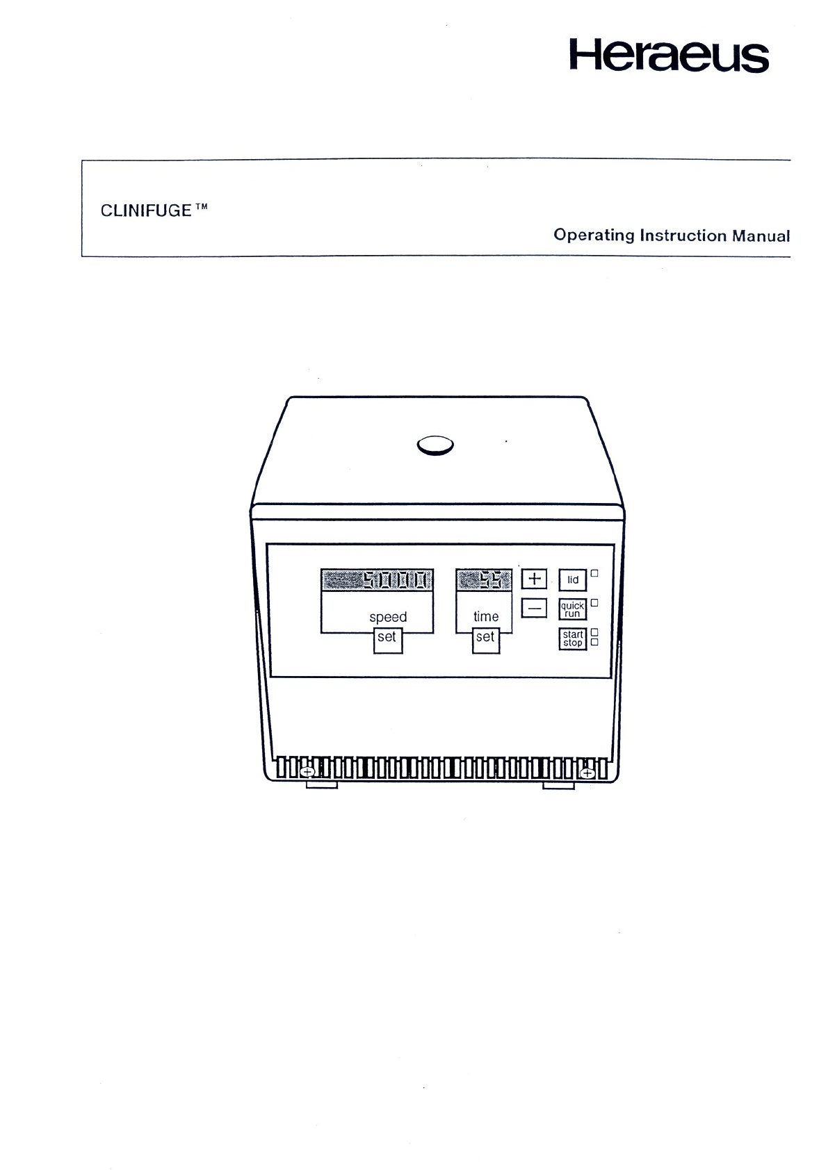
CLINIFUGE
™
Operating
Instruction
Manual
Kr
LL


READ
ME
FIRST
The
Clinifuge
centrifuge
is
designed
to
perform
a
variety
of
separation
tasks
in
small-scale
laboratories.
Before
operating,
follow
these
few
simple
cautions
and
guidelines.
A
FEW
DO'S
AND
DON'Ts
Read
all
parts
of
this
manual
carefully
before
attempting
to
operate
the
unit,
to
insure
smooth
operation
and
avoid
damage
to
the
unit
or
its
accessories.
If
a
malfunction
occurs, consult
the
Troubleshooting
Guide
at
the
end
of
this
manual.
If
problems
persist,
call
Heraeus
Instruments
at
1-800-441-2554
or
FAX
information
about
the
problem
to
Heraeus
at
1-908-754-9494.
Never
attempt
to
open
the
lid
manually
while
the
rotor
is
spinning!
Always
use tube
adaptors
when
loading
5
ml.
and
7
ml.
tubes
(see
Section
3.6).
10-,
12-
and
15-ml.
tubes
are
loaded
without
adaptors.
Complete
the
warranty
card
shipped
with
your
unit
and
return
to
the
manufacturer.
FOR
SAFETY,
NEVER
OPERATE
THE
CENTRIFUGE
IF:
-
the
lid
is
open
—
the
rotor
is
not
properly
installed
(see
Section
3.5)
-
the
expiration
date
stamped
on
the
rotor
has
passed
(see
Section
6.3)
or
the
rotor
has
been
used
more
than
10,000
cycles
(see
Section
6.2)
—
the
maximum
weight
of
a
tube
including
sample
exceeds
24
grams
or
the
density
of
the
sample
material
exceeds
1.2 g
-
cm~3
for
top
speed
operation
—
the
rotor
is
not
loaded
symmetrically
(see
Section
4.1)
Never
operate
the
Clinifuge
if
you
have
not
checked
the
maximum
centrifugal
speed
recommended
by
the
tube
manufacturer.
WARNING!
In
case
of
imbalance
(e.g.
tube
breakage
or
non-symmetrical
loading),
shut
off
power
to
the
unit
immediately.
To
accomplish
this:
1.
press
the
STOP
key
on
the
front
of
the
unit
immediately
2.
less
preferably,
pull
the
power
plug.
NOTE:
When
performing
centrifugation
and
other
functions
which
may
expose
workers
to
splashed
blood
or
body
fluids,
all
laboratory
personnel
must
follow
universal
laboratory
precautions.
For
details,
contact
your
local
laboratory
safety
officer.

Clinifuge
Centrifuge
Operation
Manual
(Revision
05/93)
READ
ME FIRST
Table
of
Contents
FAST
STARTUP
REFERENCE
GUIDE
Fig.
1.
Clinifuge
Control
Panel
Fig.
2.
Closed
Clinifuge
Fig.
3.
Opened
Clinifuge
Fig.
4.
Locking
Nut
and
Assembled
Rotor
Fig.
5.
Tube
Adaptors
and
Inserts
(optional)
ユー
ュー
ユーーーー
pre
Npnabra*
mama
Wu
그
PNRNNNNNNN
の
の
mA
よら
一
3.2.
3.3.
3.4.
DESCRIPTION
OF
UNIT
Definition
Standard
Parts
Optional
Equipment
Mechanical
Construction
Electrical
Construction
Warranty
Operating
Controls
Fig.
6.
Clinifuge
Operating
Controls
and
Control
Panel
Display
Features
.
Speed
.
Time
.
Standby
Mode
Light
SETTING
UP
THE
CLINIFUGE
Location
Electrical
Requirements
Self
Check
Cycle
Standby
Mode
Automatic
Lid
Lock
Opening
the
Lid
Emergency
Lid
Opening
Accidental
Lid
Opening
during
Run
Fig.
7.
Emergency
Lid
Opening
ROTOR
REMOVAL
AND
INSTALLATION
Rotor
Parts
Fig.
8.
Fully
Assembled
Rotor
Fig.
9.
Correct
Rotor
Installation
Fig.
10.
Disassembled
Rotor
Removing
the
Rotor
Taking
the
Rotor Apart
Fig.
11.
Rotor
Disassembly
-
Top
View
Assembling
the
Rotor
Fig.
12.
Assembling
the
Rotor
ooooums
oo oo
oo
oo
D
D
NN
NI
NN
NI
NI
3.5.
3.6.
5.2.
5.3.
5.4.
5.5.
5.5.1.
5.5.2.
6.1.
6.2.
6.3.
6.4.
6.5.
6.6.
7.
7.1.
7.2.
7.8.
7.4.
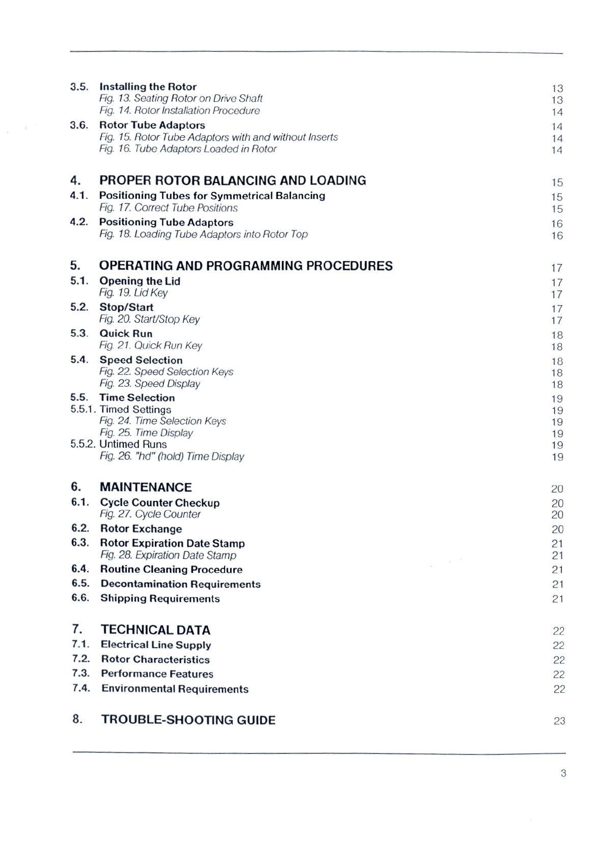
Installing
the
Rotor
Fig.
13.
Seating
Rotor
on
Drive
Shaft
Fig.
14.
Rotor
Installation
Procedure
Rotor
Tube
Adaptors
Fig.
15.
Rotor
Tube
Adaptors
with
and
without
Inserts
Fig.
16.
Tube
Adaptors
Loaded
in
Rotor
PROPER
ROTOR
BALANCING
AND
LOADING
Positioning
Tubes
for
Symmetrical
Balancing
Fig.
17.
Correct
Tube
Positions
Positioning
Tube
Adaptors
Fig.
18.
Loading
Tube
Adaptors
into
Rotor
Top
OPERATING
AND
PROGRAMMING
PROCEDURES
Opening
the
Lid
Fig.
19.
Lid
Key
Stop/Start
Fig.
20.
Start/Stop
Key
Quick Run
Fig.
21.
Quick Run
Key
Speed
Selection
Fig.
22.
Speed
Selection
Keys
Fig.
23.
Speed
Display
Time
Selection
Timed
Settings
Fig.
24.
Time
Selection
Keys
Fig.
25.
Time
Display
Untimed
Runs
Fig.
26.
"hd"
(hold)
Time
Display
MAINTENANCE
Cycle
Counter
Checkup
Fig.
27.
Cycle
Counter
Rotor
Exchange
Rotor
Expiration
Date
Stamp
Fig.
28.
Expiration
Date
Stamp
Routine
Cleaning
Procedure
Decontamination
Requirements
Shipping
Requirements
TECHNICAL
DATA
Electrical
Line
Supply
Rotor
Characteristics
Performance
Features
Environmental
Requirements
TROUBLE-SHOOTING
GUIDE
15
15
16
16
17
17
17
17
18
18
18
18
18
19
19
19
19
19
19
20
20
20
20
21
21
21
21
21
22
22
22
22
22
23

FAST
STARTUP
REFERENCE
GUIDE
Setting
Up
the
Clinifuge
1.
Set
unit
on
a
flat,
sturdy,
resonance-free
surface
in
a
well
ventilated
area.
2.
After
plugging
into
power
supply,
turn
on
the
main
power
switch
located
under
the
left
side
of
the
unit
(See
Electrical
Requirements,
Section
2.2.)
3.
Open
the
lid
by
pressing
the
LID
keypad.
4.
Remove
all
packing
materials.
Rotor
must
move
freely.
5.
If
adaptors
are
required,
remove
the
rotor
(See
Section
3.6, Fig. 15),
and
insert
adaptors
(See
Section
3.6,
Fig.
16)
6.
Mount
the
rotor
on
the
drive
shaft,
aligning
the
groove
on
the
underside
of
the
rotor
base
with
the
cross-pin
in
the
drive
shaft.
Screw
locking
nut
in
place.
(See
Section
3.5,
Figures
13
and
14
for
full
rotor
installation
instructions)
WARNING!
If
the
locking
nut
does
not
easily
engage
the
threaded
portion
of
the
drive
shaft,
do
not
try
to
force
the
rotor
further
onto
the
drive
shaft.
Instead,
remove
the
rotor
and
re-install,
making
sure
the rotor
is
correctly
seated
on
the
drive
shaft
cross
pin.
7.
Load
tubes
making
sure
the
rotor
is
symmetrically
balanced.
(See
Section
4.1,
Fig.
17
on
Positioning
Tubes.)
8.
Close
lid
making
sure both
lid
locks
are
engaged.
Display
will
read
"OPEN”
and
centrifuge
will
not
operate
if
both
locks
are
not
fully
engaged.
Programming
the
First
Run
9.
To
set
time,
press
the
SET
keypad
in
the
TIME
field.
Change
time
by
pressing
"+"
or
"~"
keypads.
10.
To
set
speed
for
a
timed
run,
press
the
SET
keypad
in
the
SPEED
field.
Change
speed
setting
by
pressing
"+"
or
"-"
keypad.
11.
For
timed
runs,
press
START
keypad.
Unit
will
shut
off
automatically.
For
untimed
runs,
press
QUICK
START
keypad
and
hold
for
desired
time.
Preparing
the
Next
Run
12.
At
end
of
cycle,
remove
all
tubes
from
rotor.
13.
Check
for
broken
glass
or
leakage
into
rotor
and/or
chamber.
14.
To
remove
rotor,
remove
locking
nut
by
turning
counter-clockwise.
Insert
index
fingers
into
opposite
tube
holes
and
lift
rotor
straight
up.
To
prevent
damage
to
drive
shaft,
do
not
lift
rotor
at
an
angle.
To
prepare
the
next
run,
follow
the
routine
cleaning
procedure
(Section
6.4),
if
necessary,
then
repeat
Steps
3to
14.
For
more
detailed
information
about
Clinifuge
features,
operation and
guidelines,
consult
other
sections
of
this
manual.
i
+]
[ia
[©
ー
|
[quick]
0
speed
time
=
set
set
sano
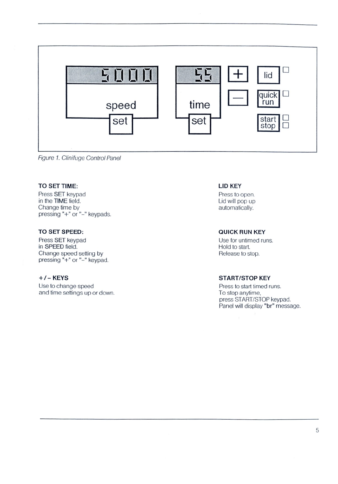
Figure
1.
Clinifuge
Control
Panel
TO
SET
TIME:
Press
SET
keypad
in
the
TIME
field.
Change
time
by
pressing
"+"
or
"-"
keypads.
TO
SET
SPEED:
Press
SET
keypad
in
SPEED
field.
Change
speed
ing
by
pressing
"+"
or
"-"
keypad.
+/-
KEYS
Use
to
change
speed
and
time
settings
up
or
down.
LID
KEY
Press
to
open
Lid
will
pop
up
automatically.
QUICK
RUN
KEY
Use
for
untimed
runs.
Hold
to
start.
Release
to
stop.
START/STOP
KEY
Press
to
start
timed
runs.
To
stop
anytime,
press
START/STOP
keypad.
Panel
will
display
"br"
message.

Figure
2.
Closed
Clinifuge
(Control
Panel)
Figure
3.
Open
Clinifuge
(down
view
w/rotor
mounted)
=
==
O
Figure
4.
Locking
Nut
&
Assembled
Rotor
Alla
Figure
5.
Tube
Adaptors
&
Inserts
(optional)
6

1.
DESCRIPTION
OF
UNIT
1.1.
Definition
The
Clinifuge
is
a
laboratory
centrifuge
used
for
a
variety
of
separation
tasks
in
small-scale
laboratories.
The
following
features
provide
easy,
efficient
operation:
—
maintenance-free
induction
drive
motor
—
microprocessor
controlled
—
no
carbon
dust
build-up
due
to
elimination
of
carbon
brushes
—
membrane
touch
pads
for
easy
cleaning
—
CSA
listed
(Canadian
Standards
Association)
-
angle
rotor
designed
to
carry
10-,
12-
and
15-ml.
tubes
(tube
adaptors
available
as
optional
equipment
for
5
ml.
and
7
ml.
tubes)
1.2.
Standard
Parts
The
Clinifuge
you
have
been
shipped
comes
with
the
following
parts:
1.
Two-part
rotor
(Figure
4)
2.
Locking
Nut
(Figure
4)
1.3
Optional
Equipment
Tube
adaptors
and
inserts
(See
Figure
5.)
1.4
Mechanical
Construction
The
Clinifuge
frame
is
constructed
of
solid steel
with
an
armor
chamber
and
a
suspension
for
the
drive
and
lid
mechanics
which
provide
extra
security
in
the
event
of
rotor
malfunction.
The
impact-resistant
plastic
casing
is
mounted
to
the
frame
to
reduce
noise
and
vibration.
Digital
displays
(LED's
-
light
emitting
diodes)
indicate
speed,
time
and
operating
conditions.
1.5
Electrical
Construction
The
Clinifuge
operates
on
one
circuit
board
using
microprocessor-controlled
digital
LED
displays
and
key
pads
on
the
face
of
the
unit
to
control
program
settings.
CAUTION:
The
microprocessor
board
is
located
directly
behind
the
front
panel.
To
avoid
electric
shock
or
damage,
only
a
factory
trained
technician
may
service
this
area.
1.6
Warranty
The
Clinifuge
is
warranted
against
defects
in
materials
and
workmanship
for
a
period
of
one
year
after
shipment
to
the
customer.
The
Clinifuge
rotor
is
warranted
against defects
in
materials
and
workmanship
for
the
period
of
10,000
cycles
or
the
expiration
date
stamped
on
the
rotor,
whichever
occurs
first.
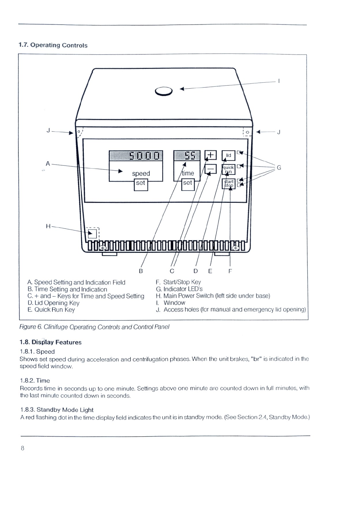
1.7.
Operating
Controls
B
ο D
E Е
A.
Speed
Setting
and
Indication
Field
F.
Start/Stop
Key
B.
Time
Setting
and
Indication
G.
Indicator
LED's
C. +
and
—
Keys
for
Time
and
Speed
Setting
H.
Main
Power
Switch
(left
side
under
base)
D.
Lid
Opening
Key
L
Window
E.
Quick Run
Key
J.
Access
holes
(for
manual
and
emergency
lid
opening)
Figure
6.
Clinifuge
Operating
Controls
and
Control
Panel
1.8.
Display
Features
1.8.1.
Speed
Shows
set
speed
during
acceleration
and
centrifugation
phases.
When
the
unit
brakes,
"br"
is
indicated
in
the
speed
field
window.
1.8.2.
Time
Records
time
in
seconds
up
to
one
minute.
Settings
above
one
minute
are
counted
down
in
full
minutes,
with
the
last
minute
counted
down
in
seconds,
1.8.3.
Standby
Mode
Light
A
red
flashing
dot
in
the
time
display
field
indicates
the
unit
is
in
standby
mode.
(See
Section
2.4,
Standby
Mode.)
2.
SETTING
UP
THE
CLINIFUGE
2.1.
Location
Remove
packing
materials
and
place
the
centrifuge
on
a
sturdy,
resonance-free
table
in
an
area
allowing
good
air
flow
in
and
around
the
unit.
Proper
ventilation
is
required
to
keep
the
motor
cool
during
operation.
A
fan
built
into
the
bottom
of
the
centrifuge
also
helps
maintain
cool
operation.
Before
operating,
be
sure
to
remove
packing
materials
inside
the
unit
used
to
secure
and
protect
the
rotor
during
shipment.
To
open
the
unit,
you
will
need
to
plug
it
in.
2.2.
Electrical
Requirements
Before
connecting
the
unit
to
the
main
power
supply,
make
certain
that:
1.
the
line
voltage
imprinted
on
the
identification
plate
is
equal
with
the
one
available
(120
Volts);
2.
the
line
voltage
circuit
breaker
is
a
15
Amp,
type
K,
slow
release
caracteristic
commonly
used
for
instruments.
A
main
power
switch
located
under
the
left
side
of
the
unit
may
be
used
to
turn
the
unit
on
and
off
as
desired.
(See
Figure
6.)
Once
the
power
supply
plug
is
connected,
the
main
switch
is
turned
on,
and
the
self-check
cycle
is
completed,
the
unit
is
ready
for
operation.
2.3.
Self
Check
Cycle
Each
time
the
unit
is
turned
on,
the
microprocessor
performs
an
automatic
self-check
of
the
electronics,
indicating
all
LED's
temporarily.
Whenever
the
centrifuge
is
disconnected
during
run,
the
unit
will
make
a
humming
sound.
When
the
self-check
is
complete,
the
yellow
LID
light
will
illuminate,
permitting
the
lid
to
be
opened.
2.4.
Standby
Mode
For
convenience,
the
Clinifuge
is
designed
to
operate
as
a
"constant
on.”
After
two
minutes
of
inoperation,
the
microprocessor
automatically
blanks
out
all
displays
and
goes
into
a
Standby
Mode,
indicated
by
a
flashing
red
LED
dot
in
the
time
display
field.
Press
any
key
to
reactivate
the
displays
and
to
perform
the
centrifugal
function.
2.5.
Automatic
Lid
Lock
The
lid
is
all-steel
construction
with
an
integrated
strobe
port
and
tabs
on
both
sides
to
engage
the
automatic
dual
lid
locks.
2.6.
Opening
the
Lid
To
open
the
lid,
turn
the
unit
on
and
press
the
LID key
pad.
The
lid
will
pop
up
automatically.
Three
conditions
will
automatically
prevent
the
lid
from
being
opened:
1.
The
unit
is
not
plugged
into
the
electrical
power
source
and/or
the
main
switch
is
not
turned
on.
2.
To
prevent
injury,
the
lid
can
not
be
opened
while
the
rotor
is
spinning.
Wait
until
the rotor
comes
to
a
full
stop
before
attempting
to
open
the
lid.
This
may
be
checked
by
looking
through
the
window
in
the
lid.
3.
If
a
power
failure
occurs
during
operation,
the
lid
will
remain
locked
until
power
returns.
In
case
of
power
failure,
the
centrifuge
always
performs
a
complete
braking
cycle.
When
power
is
restored
to
the
centrifuge,
the
“br”
code
will
be
displayed
accompanied
by
a
buzzing
sound.
To
re-start
after
braking
cycle
is
completed,
press
key
pad
for
desired
function.
(Refer
to
Emergency
Lid
Opening
instructions
in
Section
2.7.)
NOTE:
Time
and
speed
settings
are
retained
in
memory
and
do
not
need
to
be
re-entered
after
power
failure
or
between
operating
cycles.

2.7.
Emergency
Lid
Opening
WARNING!
Never
attempt
to
open
the
lid
manually
while
the
rotor
is
still
spinning.
Confirm
that
rotor
has
stopped
spinning
by
looking
through
the
round
window
in
the
middle
of
the
lid.
Disconnect
power
cord
before
using
the
following
Emergency
Lid
Opening
Procedure.
2.8.
Accidental
Lid
Opening
during
Run
If
the
lid
opens
during
a
run,
the
microprocessor
will
flash
the
LID
error
message.
Before
lifting
the
lid,
confirm
that
the
rotor
has
come
to
a
full
stop
by
looking
through
the
round
window
in
the
middle
of
the
lid.
In
case
of
a
prolonged
power
failure
or
defect,
the
LID
button
can
not
be
used
to
open
the
lid.
The
locked
cabinet
lid
can
be
opened
manually
as
follows:
1.
Disconnect
the
power
cord
before
using
the
emergency
lid
opening
procedure.
2.
Make
sure
the
rotor
is
fully
stopped
by
looking
through
the
round
lid
window.
3.
Insert
two
rods
into
the
access
holes
on
both
side
panels
(See
Figure
7)
and
unlock
the
lid,
one
side
ata
time.
Access
Hole
Access
Hole
Figure
7.
Emergency
Lid
Opening
Not
to
be
used
while
rotor
is still
spinning!
10
3.
ROTOR
REMOVAL
AND
INSTALLATION
The
Clinifuge
rotor
is
shipped
installed
in
the
centrifuge
and
secured
for
shipping.
WARNING!
Before
operating
the
centrifuge,
remove
all
packing
material
placed
inside
the
unit
for
shipping.
To
operate,
the
rotor
and
drive
shaft
must
turn
freely
and
the
rotor
nut
must
be
checked
for
tightness.
by
turning
clockwise.
For
safety
in
operation,
check
the
locking
nut
for
tightness
before
each
run
Each
time
the
rotor
is
re-installed,
the
rotor
and
chamber
must
be
completely
free
of
contamination
(dust,
glass
splinters,
etc.).
To
insure
proper
operation
and
prevent
damage,
the
rotor
must
be
properly
positioned
on
the
specially
formed
drive
shaft
each
time
it
is
re-installed.
(See
Section
3.1,
Fig.
9
and
Section
3.5.)
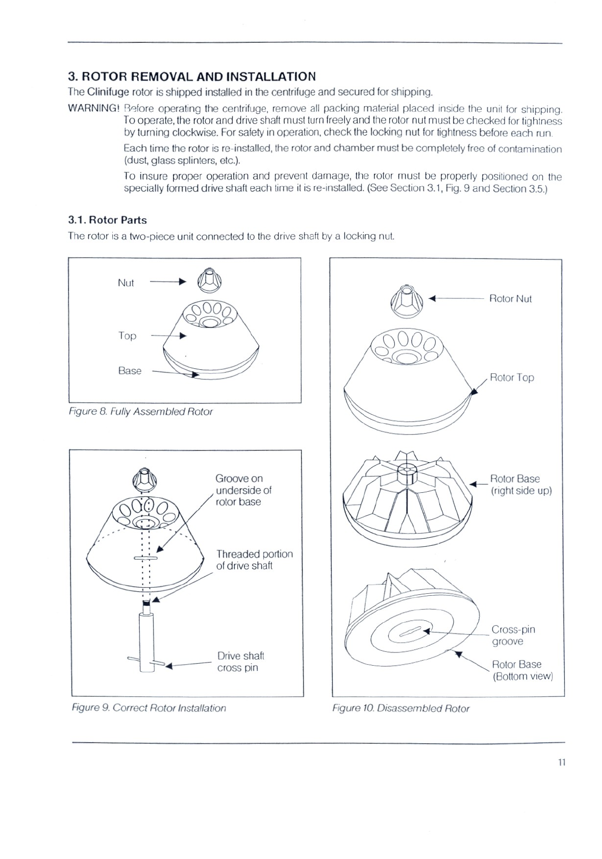
3.1.
Rotor
Parts
The
rotor
is
a
two-piece
unit
connected
to
the
drive
shaft
by
a
locking
nut.
Nut
Rotor
Nut
Rotor
Top
Figure
8.
Fully
Assembled
Rotor
É
Groove
on
<
Rotor
Base
underside
of
(right
side
up)
G
O
rotor
base
RC
Threaded
portion
NZ
of
drive
shaft
Cross-pin
groove
Drive
shaft
=
4
cross
pin
Rotor
Base
(Bottom
view)
Figure
9.
Correct
Rotor
Installation
Figure
10.
Disassembled
Rotor

3.2.
Removing
the
Rotor
To
remove
the
rotor
from
the
chamber:
1.
Open
the
lid.
2.
Remove
all
tubes
and
check
for
broken
glass.
3.
Remove
rotor
locking
nut by
turning
counter-clockwise.
4.
To
remove
rotor,
insert
index
fingers
into
holes
in
rotor
and
pull
straight
up.
If
properly
installed,
the
entire
rotor
will
lift
out.
(Before
inserting
fingers,
check
holes
for
broken
glass.)
WARNING!
Never
pull
the
rotor
up
at
an
angle.
Doing
so
could
bend
the
drive
shaft
and
cause
permanent
damage
to
the
motor.
3.3.
Taking
the
Rotor
Apart
To
separate
the
rotor
top
from
the
rotor
base:
1.
Remove
rotor
from
unit
and
place
on
a
flat
surface.
2.
Insert
index
fingers
into
empty
tube
holes
on
opposite
sides
of
the
rotor
top.
3.
Using
thumb,
press
firmly
down
on
centerpiece.
The
two
halves
of
the
rotor
should
separate
easily.
Rotor
Hole
Centerpiece
Press
here
to
separate
Rotor
Base
Figure
11--Rotor
Disassembly
—
Top
View
3.4.
Assembling
the
Rotor
1.
Before
each
installation,
clean
the
chamber
and
rotor
of
dust,
glass
splinters
and
any
other
materials.
2.
Insert
tube
adaptors,
if
required.
(See
Section
3.6,
Rotor
Tube
Adaptors
and
Section
4.,
Proper
Rotor
Balancing
and
Loading.)
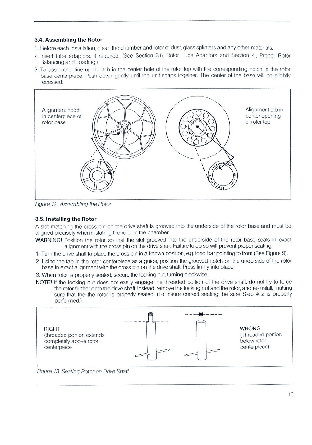
3.
To
assemble,
line
up
the
tab
in
the
center
hole
of
the
rotor
top
with
the
corresponding
notch
in
the
rotor
base
centerpiece.
Push
down
gently
until
the
unit
snaps
together.
The
center
of
the
base
will
be
slightly
recessed.
Alignment
notch
Alignment
tab
in
in
centerpiece
of
center
opening
rotor
base
of
rotor
top
Figure
12.
Assembling
the
Rotor
3.5.
Installing
the
Rotor
A
slot
matching
the
cross
pin
on
the
drive
shaft
is
grooved
into
the
underside
of
the
rotor
base
and
must
be
aligned
precisely
when
installing
the
rotor
in
the
chamber.
WARNING!
Position
the
rotor
so
that
the
slot
grooved
into
the
underside
of
the
rotor
base
seats
in
exact
alignment
with
the
cross
pin
on
the
drive
shaft.
Failure
to
do so
will
prevent
proper
seating.
1.
Turn
the
drive
shaft
to
place
the
cross
pin
in
a
known
position,
e.g.
long
bar
pointing
to
front
(See Figure
9).
2.
Using
the
tab
in
the
rotor
centerpiece
as
a
guide,
position
the
grooved
notch
on
the
underside
of
the
rotor
base
in
exact
alignment
with the
cross
pin
on
the
drive
shaft.
Press
firmly
into
place.
3.
When
rotor
is
properly
seated,
secure
the
locking
nut,
turning
clockwise.
NOTE!
If
the
locking
nut
does
not
easily
engage
the
threaded
portion
of
the
drive
shaft,
do
not
try
to
force
the
rotor
further
onto
the
drive
shaft.
Instead,
remove
the
locking
nut
and
the
rotor,
and
re-install,
making
sure
that
the the
rotor
is
properly
seated.
(To
insure
correct
seating,
be
sure
Step
4
2
is
properly
performed.)
RIGHT
WRONG
(threaded
portion
extends
(Threaded
portion
completely
above
rotor
below
rotor
centerpiece
centerpiece)
Figure
13.
Seating
Rotor
on Drive
Shaft
13

Figure
14.
Rotor
Installation
Procedure
3.6.
Rotor
Tube
Adaptors
The
Clinifuge-rotor
is
designed
to
hold
5
ml.,
7
ml.,
10
ml.,
12
ml.
and
15
ml.
tubes.
Tube
adaptors
and
inserts
(Section
1.3,
Fig.
5)
are
available
as
optional
equipment
and
tubes
must
be
positioned
as
follows:
-
10,
12
and
15
ml.
tubes
may
be
placed
directly
into
the rotor
without
adaptors
-
7
ml.
tubes
must
be
loaded
into
adaptors
without
inserts
before
being
positioned
in
the
rotor
(See
Figure
16)
- 5
ml.
tubes
must
be
loaded
into
adaptors
which
have
been
fitted
with
inserts
before
being
positioned
into
the
rotor
(See
Figure
15)
Rh
—
Top
|
Tab
Tab
Insert
(7
ml.
tubes)
會
(5
ml
tubes)
Rotor
Tube
Adaptor
without
Insert
Inserts
A
Î
Rotor
Tube
Adaptor
with
Insert
Figure
15.
Rotor
Adaptors
with
and
without
Inserts
Figure
16.
Tube
Adaptors
Loaded
in
Rotor
14
4.
PROPER
ROTOR
BALANCING
AND
LOADING
WARNING!
The
rotor
must
always
be
symmetrically
balanced
when
loading.
In
case
of
imbalance
(caused
by
tube
breakage
or
non-symmetrical
loading),
press
the
STOP
key
immediately,
pull
the
plug
or
turn
off
circuit
breaker.
To
maintain
symmetrical
balancing,
insert
tube
adaptors
in
all
empty
opposing
slots.
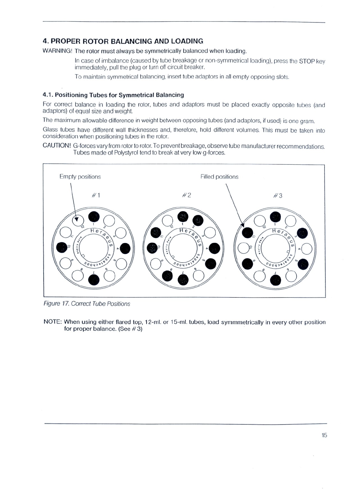
4.1.
Positioning
Tubes
for
Symmetrical
Balancing
For
correct
balance
in
loading
the
rotor,
tubes
and
adaptors
must
be
placed
exactly
opposite
tubes
(and
adaptors)
of
equal
size
and
weight.
The
maximum
allowable
difference
in
weight
between
opposing
tubes
(and
adaptors,
if
used)
is
one
gram.
Glass
tubes
have
different
wall
thicknesses
and,
therefore,
hold
different
volumes.
This
must
be
taken
into
consideration
when
positioning tubes
in
the
rotor.
CAUTION!
G-forces
vary
from
rotor
to
rotor.
To
prevent
breakage,
observe
tube
manufacturer
recommendations.
Tubes
made
of
Polystyrol
tend
to
break
at
very
low
g-forces.
Empty
positions
Filled
positions
Figure
17.
Correct
Tube
Positions
NOTE:
When
using
either
flared
top,
12-ml.
or
15-ml.
tubes,
load
symmmetrically
in
every
other
position
for
proper
balance.
(See
#
3)
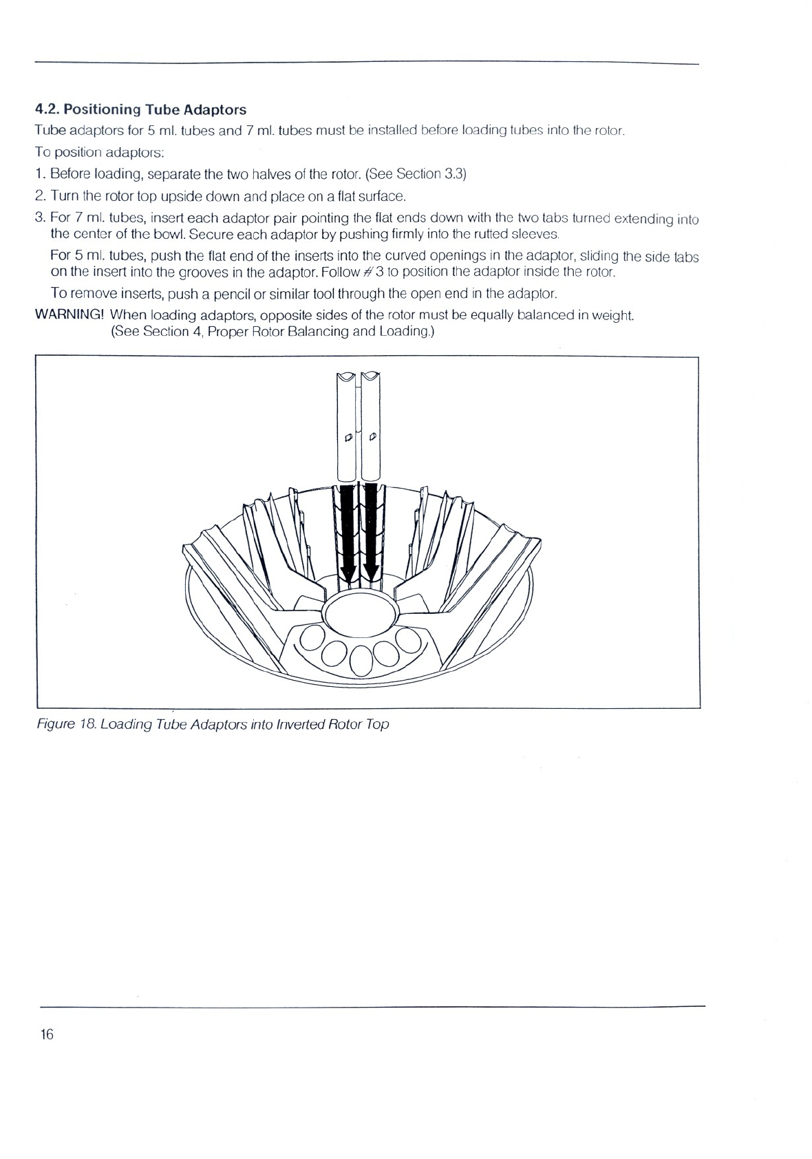
4.2.
Positioning
Tube
Adaptors
Tube
adaptors
for
5
ml.
tubes
and
7
ml.
tubes
must
be
installed
before
loading
tubes
into
the
rotor.
To
position
adaptors:
1.
Before
loading,
separate
the
two
halves
of
the
rotor.
(See
Section
3.3)
2.
Turn
the
rotor
top
upside
down
and
place
on
a
flat
surface.
3.
For
7
ml.
tubes,
insert
each
adaptor
pair
pointing
the
flat
ends
down
with
the
two
tabs
turned
extending
into
the
center
of
the
bowl.
Secure
each
adaptor
by
pushing
firmly
into
the
rutted
sleeves
For
5
ml.
tubes,
push
the
flat
end
of
the
inserts
into
the
curved
openings
in
the
adaptor,
sliding
the
side
tabs
on
the
insert
into
the
grooves
in
the
adaptor.
Follow
#3
to
position
the
adaptor
inside
the
rotor.
To
remove
inserts,
push
a
pencil
or
similar
tool
through
the
open
end
in
the
adaptor.
WARNING!
When
loading
adaptors,
opposite
sides
of
the
rotor
must
be
equally
balanced
in
weight.
(See
Section
4,
Proper
Rotor
Balancing
and
Loading.)
Figure
18.
Loading
Tube
Adaptors
into
Inverted
Rotor
Top
16

5.
OPERATING
AND
PROGRAMMING
PROCEDURES
5.1.
Opening
the
Lid
Figure
19.
LID
Key
5.2
Start/Stop
Figure
20.
START/STOP
Key
The
lid
can
be
opened
only
when
the
braking
process
is
completed
and
the
yellow
LID
LED goes
on.
To
open,
press
the
LID
key
pad.
The
lid
will
pop
up
automatically.
Once
the
unit
starts,
the
LID
key
is
disabled
for
the
entire
operating
cycle.
NEVER
TRY
TO
OPEN
THE
LID
WHILE
ROTOR
IS
TURNING.
(See
Emergency
Lid
Opening
Pro-
cedure.)
NOTE:
In
case
of
power
failure,
the
LID
key
pad
cannot
be
used
to
open
the
lid.
Follow
Emergency
Lid
Opening
Procedure,
Section
2.7,
Fig.
7.
When
the
green
START
LED
is
on,
centrifugation
may
be
started
by
pressing
the
START/STOP
key
pad.
When
the
rotor
starts
turning,
the
green
START/STOP
LED
goes
off
and
the red
LED
goes
on,
indicating
the
STOP
function
is
available.
When
the
cycle
is
completed
and
the
braking
cycle
has
ended,
the
green
START
LED
and
yellow
LID
LED
will
both
illuminate,
indicating
that
the
unit
may
be
opened
or
another
cycle
may
be
started.
To
stop
centrifugation,
press
the
START/STOP
key
pad
when
the
red
LED
is
illuminated.
After
each
stop,
the
green
START
LED
lights
up
again,
indicating
that
the
interrupted
cycle
may
be
continued
at
any
time.
If
START
is
pressed
during
the
braking
cycle
there
will
a
delay
before
the
Clini-
fuge
begins
to
accelerate.
17

5.3.
Quick
Run
Figure
21.
Quick
Run
Key
5.4.
Speed
Selection
IAN
Figure
22.
Speed
Selection
Keys
Figure
23.
Speed
Display
If
the
green
START
LED
is
on,
centrifugation
may
also
be
started
with
the
QUICK
RUN
key.
To
operate
in
QUICK
RUN
mode,
press
and
hold
the
QUICK
RUN
key
for
the
required
length
of
time.
While
the
QUICK
RUN
key
is
pressed,
the
rotor
accelerates
gradually
to
its
highest
speed.
Centrifugation
continues
until
the
key
is
released,
which
causes
the
rotor
to
brake
immediately.
If
QUICK
RUN
is
pressed
again,
acceleration
will
be
re-activated.
The
QUICK
RUN
key
may
be
used
for
runs
requiring
less
than
one
minute.
(Braking
will
still
require
the
same
time.)
The
QUICK
RUN
key
may
also
be
used
to
override
the
speed
set
in
programming)
Speed
is
adjusted
in
gradations
of
100 revolutions
per
minute.
Speed
settings
are
retained
in
the
unit's
memory
during
standby
periods,
and
need
be
entered
only
if
changing
the
previously
set
value.
When
the
centrifuge
is
in
Standby
Mode,
the
display
screens
for
TIME
and
SPEED
are
blank.
To
activate,
press
the
SET
key
pad
in
the
SPEED
field.
The
previously
set
speed
will
appear,
flashing
the
digit
in
the
100ths
position
in
the
speed
display
window.
Set
the
new
speed
up
or
down
using
the
"+"
or
"="
keys.
After
entering
the
new
speed,
press
the
SET
key
pad
in
the
SPEED
field
again
to
replace
the
previously
set
speed
in
memory.
The
speed
setting
mode
is
complete.
18
Table of contents
Other Heraeus Laboratory Equipment manuals


Popular Laboratory Equipment manuals by other brands

Biotage
Biotage TurboVap user manual

AFi
AFi KATRINA Maintenance manual

Metkon
Metkon VACUMET 52 Operation & instruction manual

MICROLIT
MICROLIT EASYFILL Operation manual

Thermo Scientific
Thermo Scientific 1310 operating instructions

PerkinElmer
PerkinElmer LED Solutions ACULED Designer Kit Silver user manual

PerkinElmer
PerkinElmer Clarus SQ 8 MS Series Hardware guide

PerkinElmer
PerkinElmer UATR user guide

Tripp Lite
Tripp Lite NPOE-30W-1G owner's manual

New Era Pump Systems
New Era Pump Systems NE-1000 Multi-Phaser manual

Lightwave
Lightwave EasyCheck EC400KD instruction manual

Master cool
Master cool 53123 quick start guide


