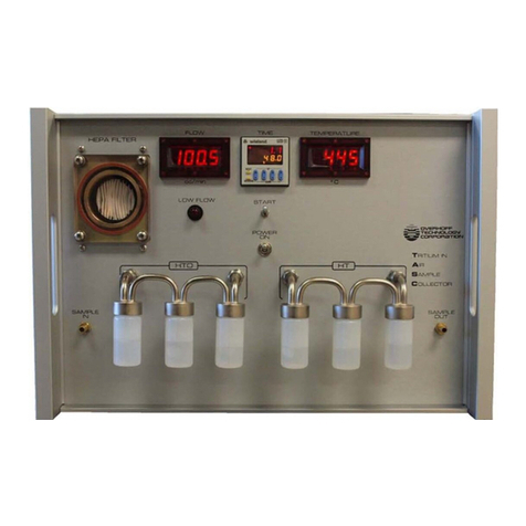
overhoff TRIATHALON-H3 User manual

TRITIUM MONITOR
TRIATHALON-H3
with optional Totalizer
OPERATION AND MAINTENANCE MANUAL
Revision 0
DATE: 20-Aug-2014
Generic Version
OVERHOFF TECHNOLOGY CORPORATION
1160 US ROUTE 50, MILFORD, OHIO, USA

TABLE OF CONTENTS
Section I. Introduction Page
1 General Description 2
2 Physical Description 2
3 Features 3
4 Performance Specifications 4
5 Principle of Ion Chamber Measurments 6
Figure – Front View 9
Figure – Block Diagram 10
Figure – Customer Connections 11
Section II. Installation
1 General 12
Figure – Installation Diagram 13
2 Equipment Checklist 14
3 Storing, Handling, Unpacking 14
4 Assembly 15
5 Maintenance 16
Section III. Drawings and Schematics 17
Enclosure General Layout, Exterior 18
Enclosure General Layout, Interior 19
Pneumatic Diagram 20
Section IV. Operation 21
1 Startup 22
2 Shutdown 22
3 Main Screen 23
4 About Screen 25
5 Setup Screen 26
6 Datalogging 32
7 Software Upgrade Procedure 33
8 Network Addressing 34
9 4-20 mA Connection (optional) 34

2
1.0. GENERAL DESCRIPTION
This tritium monitor consists of dual 2-liter ionization chambers with an integral
electrometer coupled to the electronic circuits for display and control inside one fiberglass
reinforced plastic molded enclosure suitable for wall mounting.
One ionization chamber, referred to as the measurement or upstream chamber,
measures in a positive manner. The second ionization chamber, referred to as the
compensation or downstream chamber, is identically constructed but subtracts from the
measurement of the upstream chamber. This is how dual chambers serve to cancel the
effects of external gamma fields and provide differential measurements.
Ionization chambers respond not only to the airborne radioisotope, which circulates
through the ionization chamber, but also respond to the presence of external high-energy
radiation capable of ionizing the air inside. Therefore, ionization chambers will respond
to X-rays and gamma radiation as well. Additional gamma radiation suppression can be
accomplished by using lead shielding. The electrometer serves to transform this current
into a form and magnitude suitable for display, alarm, and external uses, as the ionization
current itself is very weak.
The monitor contains all signal processing, alarm and external interface circuits, read out,
and all required power supplies. The signal processing circuits serve to reject unwanted
signals and to translate the electrometer signal voltage into a form and magnitude
suitable for display, alarm and external uses as well.
The alarm circuits provide a visual signal and relay outputs for remote connection to
denote that a preset level of measurement has been exceeded or certain malfunctions.
2.0. PHYSICAL DESCRIPTION
The Model Triathalon-H3 is a single range, ionization chamber monitor for the measurement
of tritium in a NEMA 4X enclosure suitable for permanent installation and for continuous duty.
The enclosure has a hinged door with a polycarbonate window. Behind the hinged door is a
front panel that is hinged so that it can be opened for servicing the various components
inside. The sample inlet and exhaust fittings are located on the left side of the enclosure.
Fittings for Tritium and Total Tritium measurement are located on the right side of the
enclosure. Wiring conduit connections are provided on the bottom of the enclosure and
consist of AC power conduit and control wiring conduit.
The following are located on the front panel:
Fuse holder, main power switch, ‘ON’ and ‘OFF’ indicators.
An LCD color touch screen serves the majority of control and display functions. These
include the tritium measurement, alarm set points and indication.
A 0-10 LPM adjustable flowmeter to indicate and control the sample flow.
The following are attached to the enclosure subpanel inside the enclosure:
Dual 2 liter ionization chamber;
Sample pump, differential pressure switch used for sensing a low flow condition, and all
DIN rail mounted electrical connections.
The following are located on the outer left side of the enclosure:
Stainless steel tubing connections for sample inlet and exhaust
HEPA filter for downstream sample stream.
The following are located on the outer right side of the enclosure:
Hose connections for a desiccant column used for noble gas compensation mode
HEPA filter for downstream sample stream.

3
3.0. FEATURES
While the basic purpose of the Overhoff Model Tiathalon-H3 tritium monitor is to measure
the presence and level of tritium (HTO and HTO+HT), this particular instrument,
described herein, has these special features.
1. Tritium Monitoring measurement range over four plus decades, using dual ionization
chambers with a nominal volumes of 2 liters each.
2. One ionization chamber (measurement or upstream) serves to collect the current
produced as tritium decays radioactively. The second ionization chamber
(downstream or compensation) is identically constructed, but subtracts from the
measurement of the upstream chamber. Overhoff tritium monitors are equipped with
special circuitry to identify and reject ionization currents that are produced by
decaying radon, or other airborne alpha emitting radioisotopes.
3. There is an internal pump system for sample transport through the ionization
chamber.
4. The Model Tiathalon-H3 consisting of the tritium monitor and the pump system as
described above provides all data and performs all local control functions.

3
4.0. PERFORMANCE SPECIFICATIONS
The following specifications will apply when this is used for the measurement of tritium:
4.1. MEASUREMENT
Range 1 – 19999 μCi/m3
Display LCD color touch screen
Accuracy ±5 % of reading, ±L.S.D., whichever is greater
Stability and Drift ±1μCi/m3long term (thirty days), ambient temperature conditions
Noise ±1μCi/m3, 1 sigma, with alpha suppression in use
Response Rate two linear electronic time constants
approximately 20 seconds for signals up to about 80 μCi/m3
approximately 3 seconds for signals above 80 μCi/m3
Gamma A second ionization chamber of equal volume, mounted on the
Compensation same axis, serves to cancel effects of external gamma fields
Offset Compensation: Manual compensation control provided to offset the effects of
gamma radiation and/or tritium build-up
Over Range Indication The LCD screen will flash when the measurement has exceeded
19999 μCi/m3
Warm Up Time: less than five minutes
4.2. ALARM SYSTEMS
Tritium Level There are two Tritium Level Alarms, the indicator on the LCD is
normally green and the message displayed is “Tritium Level OK”.
Alert Level Tritium Alert Level Alarm preset from 1 – 1000 μCi/m3. Upon a
Tritium Level Alarm the indicator on the LCD will turn yellow and
display “ALERT LEVEL ALARM”.
High Level Tritium Level Alarm preset from 10 – 10000 μCi/m3. Upon a
Tritium Level Alarm the indicator on the LCD will turn red and
display “HIGH TRITIUM LEVEL”.
Mode Default mode for level alarms is non-latching, Enter SET-UP to
select either latching or non-latching modes.
Malfunction Two conditions initiate a MALFUNCTION ALARM
1. Power Supply Fault; Upon any failure of the low voltage power
supplies, the LCD will turn red and display “POWER SUPPLY
FAULT LV. Upon any failure of the high voltage bias supplies,
the LCD will turn red and display “POWER SUPPLY FAULT HV.
2. Sample flow; upon a low flow condition, the LCD will turn red
and display “LOW FLOW”.
Relay closure Relays for all alarms operate in the failsafe mode

5
4.3. IONIZATION CHAMBER
VOLUME measuring: 1,600 cm3
total wetted: 2,000 cm3
ELECTRODES Solid wall on both sides
GASKETS silicone rubber
PRESSURE 0.1 to 2 atmospheres
PORTS 3/16’’ I.D. Vinyl Tubing
MATERIALS OF all wetted surfaces, stainless steel
CONSTRUCTION
4.4. EXTERNAL SAMPLE 3/8’’ O.D. Stainless Steel Swagelok Fittings
CONNECTIONS
4.5. FLOWMETER 0-10 LPM adjustable rotameter
4.6. DUST AND high efficiency 99.99% at 0.1 microns cartridge type
ELECTROSTATIC Solberg Manufacturing Product No. HE04
FILTER
4.7. PUMP long life continuous duty linear motor driven diaphragm
type, Medo Model VCO201E1
4.8. ENVIRONMENTAL storage: -30°C to +50°C
TEMPERATURE operating: 5°C to +50°C
HUMIDITY 0 to 95 % R.H.
4.9. REMOTE INTERFACE refer to Figure 3, Customer Connections
SCREW TERMINALS high and low analog outputs
CONNECTIONS alarm relay outputs
4.10. POWER 115 VAC, 50/60 Hz, 5A, single phase
4.11. PHYSICAL
ENCLOSURE Molded fiberglass with polycarbonate window on a
hinged door. Color: light gray, NEMA 4X, IP66
DIMENSIONS 16.2’’ Wide x 20.3’’ High x 9.19’’ deep
[41.2cm Wide x 51.5cm High x 23.4cm deep]
WEIGHT 43 lbs [19.6 kg]

6
5.0. PRINCIPLE OF IONIZATION CHAMBER MEASUREMENTS
A tritium monitor is an instrument using flow through ionization chambers designed to
determine the presence and level of radioactive gas (tritium) in air or other gas streams.
These monitors may be used to detect radioactive gases in many applications like:
room air
stacks, hoods, or other effluent passages
process piping
glove boxes, and similar
These monitors are generally calibrated in terms of (micro) Curies per cubic meter though
other units can be used as requested (Bequerel, pCi/cm3, etc.).
The principle of measurement is based on collecting the current that is generated by the
radioactive decay (of tritium) inside an ionization chamber. The ionization current is
proportional to the total activity of the radionuclide (tritium) being detected.
A tritium monitor consists of the following parts:
1. An ionization chamber to collect the ionization current.
2. A sampling system to circulate the sample (air) through the ionization chamber.
3. An electrometer to amplify the very weak ionization current.
4. All other associated electronics to process and display the signal.
Ionization chambers respond not only to the airborne radioisotope, which circulates
through the ionization chamber, but also respond to the presence of external high energy
radiation capable of ionizing the air inside. Therefore, ionization chambers will respond
to X-rays and gamma radiation as well.
To overcome this effect, Overhoff Technology Corporation (Overhoff) tritium monitors are
sometimes supplied with compensating ionization chambers. Here a second ionization
chamber is used to cancel the effects of external radiation. Overhoff tritium monitors are
equipped with special circuitry to identify and reject ionization currents that are produced
by decaying radon, or other airborne alpha emitting radioisotopes.
5.1. CONTAMINATION, PLATE OUT OF HTO
When measuring significant levels of tritium for any but very short periods of time, the
walls of the ionization chambers will become coated with a thin layer of tritium oxide.
This leads to a background signal, where value may vary with time and is larger than the
minimum desired signal level.
5.2. DUST FILTERS
Dust filters must always be included in the sample flow stream upstream of the ionization
chamber. Accretion of dust, in even the slightest amount, results in erratic and noisy
instrument behavior. If accumulation of dust and dirt in the ionization chamber is allowed
to continue, the chamber will ultimately have to be disassembled and cleaned out. An
arcing due to dirt build up can also destroy the sensitive electrometer circuit.

7
5.3. RESPONSE OF IONIZATION CHAMBERS TO RADIATION
The current generated in an ionization chamber is the result of collecting electrons
generated from ionization of gas caused by occurrence of a nuclear event in the gas
inside.
The number of ions (magnitude of the current) is influenced by numerous factors like
energy, physical nature and particle range. As a good rule of thumb for beta particles in
air, one secondary electron (and one positive ion) is formed for every 34 electron volts of
energy lost by the primary beta particle as it travels its path.
The Curie is defined as 3.71 x 10¹⁰ nuclear decay events per second. The mean energy
of tritium decay is 5.69 kev. Therefore it is calculated that 1 Curie of tritium produces an
ion current very close to
1 x 10⁻⁶ amperes.
A concentration of 1 μCi/m3of tritium in a chamber of a volume of 1 liter will thus produce
a current of
1 x 10-15 amperes.
It must be remembered that the ionization chamber responds to the quantity of tritium
present inside. This is to say that effects due to temperature and pressure may,
depending upon the circumstances of measurement, need to be accounted for. Even if a
sample of gas is known to contain tritium at a certain concentration, i.e., parts per million
or other, it must be remembered that the activity, i.e., amount per unit volume, is
nevertheless dependent upon temperature and pressure. The ionization chamber only
responds to the quantity of radioactivity inside.
Ionization chambers also exhibit several other peculiarities. The wall effect can be a
problem if the track length of the decaying particle is appreciable when compared to the
dimensions of the chamber.
For ionization chambers with small linear dimension, and if the track of ionized particles is
comparatively long (the mean free path), an appreciable part of the energy of the primary
particle is simply dissipated in the wall of the ionization chamber. This effect increases
as the chamber dimensions shrink, and decreases as the chamber dimensions increase.
In air, atmospheric pressure, the maximum mean free path of a tritium beta particle is of
the order of five millimeters, and for chambers with linear dimensions of ten centimeters
or greater this “wall” effect becomes negligible.
At high concentrations, another effect takes place.
When the ion population density is high, some of these positive and negative ions will
recombine and are lost to the measurement electrode.
This is known as saturation or as stagnation since the effect is more pronounced in
corners of the ionization chamber where the potential field gradient is low. Increasing the
ionization chamber voltage can reduce the effect.
For measurements of tritium at very high concentrations, such as are required when
working with pure T2, special chamber geometry is employed. Long slender ionization
chambers, with relatively large internal ion collecting electrodes and short spacing
between the chamber elements will enhance field gradients. With even moderate
polarization potentials of 100 V or so, such chamber geometry shows linear response
even to pure tritium streams.

8
5.4. DISCRIMINATION AGAINST ALPHA PULSES
Since the energy of an alpha decay is at least 10,000 times more active than that of a
tritium beta event, suppression of alpha pulses needed in order to distinguish the
presence of tritium at low levels. Stable and accurate measurements of tritium for values
below 50 μCi/m3can only be obtained with means to suppress response to alpha decay.
Alpha decay events, as detected in an ionization chamber, are not instantaneous. The
special circuitry, which recognizes the alpha pulses, requires some amount of time to
suppress the event. During pulse suppression, the instrument analog circuitry is placed
in a “holding” mode; response is frozen during the interval associated with the alpha
event. The holding intervals occur at random, but effectively add to the apparent time
constant of the electronics. The instrument response becomes slower with increasing
radon or gamma noise background. For large background the instrument will even
freeze completely, the alpha pulse light will be permanently illuminated.
5.5. TECHNICAL SPECIFICATIONS
The proposed instrument will be designed and constructed for your particular application.
It will be built and tested to these specifications.
Circuit diagrams and interconnections between parts of the monitor, as well as those
leading to user selected remote devices or interfaces, will be provided with the
maintenance manual.
Consult the factory for further information, or for application engineering at
1160 US Route 50, P.O. Box 182
Milford, OH 45150-9705, USA
Telephone (513) 248-2400
Facsimile (513) 248-2402


TerminalNo. Description
TB1‐0 ChassisGround
TB1‐1 From115VACSource(Neutral)
TB1‐2 From115VACSource(Line)
TB1‐8 LowAnalogOutput(AnalogCommon)
TB1‐9 HighAnalogOutput(0‐10V)
TB1‐10 ResetTotal,switchclosure
for2secondsminimumwithTB1‐11
TB1‐11 ResetTotal,switchclosure
for2secondsminimumwithTB1‐10
TB601‐1 HighLevelAlarmNo.1,N.C.
TB601‐2 HighLevelAlarmNo.1,N.O.
TB601‐3 HighLevelAlarmNo.1,COM.
TB601‐4 HighLevelAlarmNo.2,N.C.
TB601‐5 HighLevelAlarmNo.2,N.O.
TB601‐6 HighLevelAlarmNo.2,COM.
TB601‐7 AlertLevelAlarmNo.1,N.C.
TB601‐8 AlertLevelAlarmNo.1,N.O.
TB601‐9AlertLevelAlarmNo.1,COM.
TB601‐10 AlertLevelAlarmNo.2,N.C.
TB601‐11 AlertLevelAlarmNo.2,N.O.
TB601‐12 AlertLevelAlarmNo.2,COM.
TB601‐13 MalfunctionAlarmNo.1,N.C.
TB601‐14 MalfunctionAlarmNo.1,N.O.
TB601‐15 MalfunctionAlarmNo.1,COM.
TB601‐16 MalfunctionAlarmNo.2,N.C.
TB601‐17 MalfunctionAlarmNo.2,N.O.
TB601‐18 MalfunctionAlarmNo.1,COM.
ModelTRIATHALON‐H3CustomerConnections
FIGURE 3
CUSTOMER CONNECTIONS

12
SECTION II. INSTALLATION
1.0. GENERAL
The following instructions include all information necessary for the correct installation of
the equipment and for the verification of proper operation.
The following information is covered by these instructions:
1. Equipment Checklist
2. Installation Details
3. Storage, Handling and Unpacking
4. Assembly
Equipment Supplied
The following equipment has been supplied by the manufacturer:
1 each, Tritium Monitor, Overhoff Technology Model Triathalon-H3
Monitor is enclosed in a fiberglass case ready for wall mounting
Dimensions: 16.2’’ Wide x 20.3’’ High x 9.19’’ deep
[41.2cm Wide x 51.5cm High x 23.4cm Deep]
Excluding door handle and mounting hardware
Weight: 43 lbs [19.6 kg]


14
2.0. EQUIPMENT CHECK LIST
The equipment is packaged in cardboard containers marked in accordance with
Packaging and Delivery Procedures.
The contents of the container(s) is as follows:
Carton 1 of 1, 1 each, Tritium Monitor Overhoff Technology Model Triathalon-H3
3.0. STORAGE, HANDLING, UNPACKING
This equipment has been packaged to protect it against damage while stored for
extended periods of time in ordinary storage (dry warehouse) facilities.
STORAGE
The individual pieces are protected with plastic wrap and packed in boxboard containers
containing one pouch of drying agent to prevent corrosion from high humidity.
The plastic wrapping should not be broken open until the equipment is ready for
installation.
The equipment should be protected from damage, should not be dropped, and should be
protected from extreme temperatures. Storage conditions of -30°C to +50°and 0 – 95%
RH are recommended.
HANDLING
The equipment consists of moderately fragile electronic equipment and should be
handled with care. It should not be dropped, subjected to mechanical stress or extreme
temperatures.
Evidence of surface damage, creases or tears to the box board containers should be
reported at once. If the damage is more than superficial, the container should be opened
and the plastic wrap inspected for tears. If torn, inspect the contents for damage. If there
is no damage to the equipment, repair the tear in the plastic wrap with heavy-duty
adhesive tape. Damaged equipment should be reported at once.
UNPACKING
The equipment should not be unpacked until ready for installation.
When ready for installation, the equipment should be unpacked at the site. No special
tools are required for unpacking. Use a sharp knife to cut the adhesive tape seals on the
box board containers. Evidence of corrosion of physical damage should be reported at
once.
The equipment should be lifted carefully out of the carton and the plastic cover carefully
unwrapped.
The carton(s) and plastic cover(s) may be retained for future use in the event that the
equipment is to be returned to storage. Retain the installation instructions for used by the
appropriate personnel.

15
4.0. ASSEMBLY
Assembly work consists of:
1. Attaching the enclosure to the wall using the appropriate anchors and tools as
required.
2. Attaching conduit and wiring.
3. Attaching stainless steel tubing between the monitor and the existing pumping unit,
as well as tubing to and from the sampling point for the pumping unit.
ENCLOSURE AND PUMPING UNIT
Pictorial installation instructions are enclosed with each unit. These units are to be
permanently attached to the wall using lead anchors or similar means. The monitor and
associated pumping unit may be located close to each other, but spaced sufficiently to
permit ease of access for piping and conduit installation.
SAMPLE CONNECTIONS
Sample inlet and outlet connections are attached to the fiberglass enclosure 3/8’’ O.D.
Stainless Steel tubing compression type.
CONDUIT AND WIRING
The power requirement is 115VAC, 60Hz, 5A, single phase. Conduit fittings are located
on the bottom of the enclosure to be used for AC power supply to the tritium monitor as
well as control wiring connection. Install the conduit as required. Install the AC wiring
between the monitor and existing pumping unit. Use wiring of the appropriate type and
current rating. Install wiring for signal and relay connections as required.
Return all keys used to lock the door to the appropriate personnel.

16
5.0 MAINTENANCE
The Triathalon series instruments have been designed for many years of trouble free
service.
Periodic or routine maintenance is comprised mainly of regular inspection of the dust
filter, ensuring that it is replaced if it appears to be dirty.
5.1. OPERATOR MAINTENANCE
The following operational checks may be performed at monthly intervals or sooner.
Inspect dust filter for excessive dust build up. Check the flowmeter indication to verify a
maximum flow rate above 10 liters per minute. Return the flowrate to the recommended
value of 4-6 LPM or as otherwise established for your particular installation.
Use a gamma check source to check operation of the instrument.
Manipulate the alarm set point potentiometer to verify correct functioning of the alarm.
If the instrument is suspected of DRIFT, the zero reading may be verified. This should be
done by an instrument engineer or technician.
5.2. SUPERVISORY MAINTENANCE
The following tasks are the responsibility of the supervisory engineering staff.
1. Calibration verification is to be performed at yearly intervals, or as otherwise
specified.
2. Response checks (in case of need for cursory verification of the operational status of
the ionization chambers and of the whole system), of the system may be tested by
using a low strength gamma radiation check source. This must be done under the
strict supervision of a health physicist. The gamma source is brought into proximity
of each ionization chamber and the response is observed.
5.3. FACTORY MAINTENANCE
A determination that the system appears to have suffered a functional failure should
require that the factory be notified (telephone (513) 248-2400, facsimile (513) 248-2402).
Engineering assistance via telephone or facsimile, will be supplied by the manufacturer
OVERHOFF TECHNOLOGY CORPORATION.
Should it appear to be necessary to return the instrument to our factory, authorization for
the return must be obtained from Overhoff Technology Corporation prior to shipping.
In-freight charges will be borne by the customer.

SECTION III. DRAWINGS AND SCHEMATICS
DRAWING DESCRIPTION
NUMBER
1021345 Enclosure General Layout, Model Triathalon-H3
Sheet 1 of 2
1021345 Enclosure General Layout, Model Triathalon-H3
Sheet 2 of 2
1021345-PD Pneumatic Flow Diagram, Model Triathalon-H3
17


Table of contents
Other overhoff Laboratory Equipment manuals