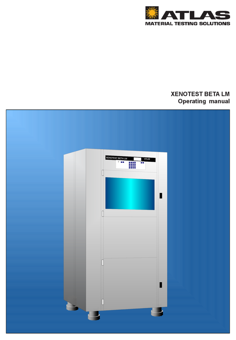
Atlas XENOTEST 150 S+ User manual

Operating Instructions
Xenotest®150 S+

2
Operating Instructions Xenotest®150 S+

3
Operating Instructions Xenotest®150 S+
Copyright
These operating instructions are protected by copyright. Rights resulting thereof, particularly
reprint, photomechanical or digital postprocessing or reproduction, even in part, are only
allowed with the written consent of ATLAS Material Testing Technology GmbH.
This regulation does not apply to reproductions for in-plant use.
The contents of the operating instructions are subject to change without further notice.
For translations into foreign languages, the German version of the operating instructions
is binding.
2006, Atlas MTT GmbH • D-63589 Linsengericht • Germany

4
Operating Instructions Xenotest®150 S+
Contents
1 Safety instructions.................................................................................. 6
1.1 Explanation of symbols ........................................................................ 8
1.2 Use of the instrument........................................................................... 9
1.3 Safety features of the instrument ........................................................ 9
2 Delivery of the instrument ................................................................... 11
2.1 Packaging ...........................................................................................11
2.2 Standard equipment ............................................................................11
3 Location requirements ......................................................................... 12
3.1 Room climate ..................................................................................... 12
3.2 Room ventilation ................................................................................ 12
3.3 Instrument exhaust air system .......................................................... 12
3.4 Water supply system ......................................................................... 13
3.5 Transport ............................................................................................ 14
3.6 Space requirements ........................................................................... 14
4 Description of the instrument ............................................................. 16
4.1 Front and right view ........................................................................... 16
4.2 Rear, left and top view ....................................................................... 17
4.3 View of the test chamber ................................................................... 18
4.4 View of the operating panel ............................................................... 19
5 Functional description ......................................................................... 20
5.1 Program control ................................................................................. 20
5.2 Absorption filter system ..................................................................... 21
5.3 Overview of the filter systems ........................................................... 23
5.4 Irradiation system .............................................................................. 24
5.5 Ventilation system .............................................................................. 25
5.6 Misting and humidification functions.................................................. 26
5.7 Measuring and control sensor system .............................................. 27
6 Start-up ................................................................................................... 28
6.1 Initial start-up ..................................................................................... 28
6.2 Checking the instrument components ............................................... 28
6.3 Installation and removing the xenon lamp ........................................ 29
6.3.1 Removing the xenon lamp ................................................................. 30
6.3.2 Xenon lamp installation...................................................................... 31
6.4 Filter replacement .............................................................................. 32
6.5 Loading sample holders .................................................................... 34
6.6 Installing / removing optionale sensors ............................................. 36
6.7 Filling the water reservoir .................................................................. 38
6.8 Connecting the exhaust air system ................................................... 39
6.9 RS 232 interface set-up ..................................................................... 40
6.10 Power supply connection ................................................................... 40
6.11 Set-up for optional printer .................................................................. 42

5
Operating Instructions Xenotest®150 S+
Contents
7 Operation ............................................................................................... 44
7.1 Menu structure of the instrument control ........................................... 44
7.2 Operating the touch screen ............................................................... 45
7.3 Switching the instrument on .............................................................. 46
7.4 Starting the test program ................................................................... 47
7.5 Adjusting the test chamber humidity ................................................. 48
7.6 Test program settings ........................................................................ 49
8 Shut-down .............................................................................................. 50
8.1 Switching the instrument off .............................................................. 50
8.2 Emergency shut-off ............................................................................ 50
8.3 Removing samples ............................................................................ 50
9 Maintenance .......................................................................................... 51
9.1 Inspection ........................................................................................... 51
9.2 Repairs ............................................................................................... 51
9.3 Service ............................................................................................... 52
9.4 Cleaning ............................................................................................. 54
10 Technical data ....................................................................................... 56
11 Accessories ........................................................................................... 57

6
Operating Instructions Xenotest®150 S+
1 Safety instructions
Atlas Material Testing Technology GmbH
Vogelsbergstr. 22
D-63589 Linsengericht
Phone ++ 49 / 6051 / 707-140
Fax ++ 49 / 6051 / 707-149
Notes for users:
These operating instructions describe the Xenotest®150 S+ weathering instrument.
Please note that only properly trained personnel with appropriate qualifications must work
on this instrument.
The following people are considered to be qualified personnel:
• Those who have obtained their knowledge through specialized training;
• Those who have been trained in the operation and operating features of the
Xenotest®150 S+ on the basis of these operating instructions;
• Those who, on the basis of their professional activities and professional experi-
ence and training with regard to safety-related regulations, are capable of as-
sessing and recognizing potential work hazards.
Service:
• The lamps in the instrument must be replaced only by qualified personnel that
has been trained by a qualified electrician.
Cleaning:
• The instrument and any instrument components must be cleaned only by trained
cleaning personnel.
Please read these operating instructions carefully prior to the first use of the
Xenotest®150 S+ in order to fully utilize the instrument's capabilities and to avoid
possible damage.
Should a particular problem occur which you feel is not adequately treated in
these operating instructions, we urge you for your own safety to contact your
supplier.

7
Operating Instructions Xenotest®150 S+
1 Safety instructions
Notes for operators:
The Xenotest®150 S+ has been manufactured with the current state-of-the-art pro-
cesses and parts. It is operationally safe; nonetheless, this instrument can pose hazards,
particularly if it is operated by inadequately trained personnel or if it is employed for
any other than its intended and designated purpose:
Start-up and service:
• For start-up, the lamps and filters must be installed only by a qualified electrician.
• Subsequently, lamps in the instrument must be replaced only by qualified per-
sonnel that has been trained by a qualified electrician.
Training and accident prevention:
• For personnel operating the instrument, the operator must prepare written in-
structions in a reasonable form based on these operating instructions and in
the language of the operating personnel (Germany: Accident Prevention Regu-
lations, UVV VGB 1 § 7, 2).
• The regulations of the trade associations concerning safety and health at the
workplace (BGV A 2) must be observed.
• Use these operating instructions to familiarize the operating and cleaning per-
sonnel with the functions, operation, and care of the instrument.
• For safety reasons, any unauthorized changes or modifications to the instru-
ment are not allowed.
Warranty:
The Atlas MTT GmbH warrants the operational safety and functions of the instrument
only under the condition that:
• only original spare parts and accessories that have been approved by Atlas MTT
are used,
• inspections and maintenance are performed at the specified intervals.
Validity of the operating instructions:
• The contents of the operating instructions are subject to change without further
notice.
• Concerning translations into foreign languages, the German version of the ope-
rating instructions is binding.
Store these operating instructions in the vicinity of the instrument in order to be
able to refer to the safety information and important operating information at any
time.

8
Operating Instructions Xenotest®150 S+
1 Safety instructions
1.1 Explanation of symbols
Symbols in the operating instructions:
WARNING!
Non-observance may result in serious injuries or death.
CAUTION!
Non-observance may result in minor to medium injuries or physi-
cal damage.
NOTE!
Provides application tips and useful information.
Warning against hazardous solvents.
Warning against hot surface.
Warning against electric shock.
Symbols on the instrument:
WARNING AGAINST A HAZARD!
Caution! Observe the operating instructions.
HOT SURFACE!
Warning against the risk of burns.
REFERENCE TO DISPOSAL DIRECTIVE (WEEE)!
The disposal of this product must comply with the EC Directive
2002/96/EG concerning used electrical and electronic instruments
(WEEE).

9
Operating Instructions Xenotest®150 S+
1 Safety instructions
1.2 Use of the instrument
Correct use:
• The Xenotest®150 S+ is used for exposing material samples to irradiation and
weather.
• The instrument is suitable for continuous operation.
• The Xenotest®150 S+ has been tested for electromagnetic compatibility and is
suitable for installation in industrial applications.
Incorrect use:
• The Xenotest®150 S+ must not be operated in rooms that do not comply with
the location requirements.
• Do not use tissues, substances or liquids as samples if they are easily ignitable
or explosive.
• Do not use tissues, substances or liquids as samples if they release poisons.
1.3 Safety features of the instrument
Safety requirements:
• DIN EN ISO 12100, Part 1, Part 2 Issue 2004-04
Safety of machinery
• DIN EN 61010, Part 1 Issue 2002-08
Safety regulations for electrically operated measuring, control and laboratory
instruments. General requirements
• DIN EN 61010-2-010 Issue 2004-06
Risks from partial control failures
• DIN EN 50178 (VDE 0160): 1998-04
Equipment of high-voltage systems with electronic resources
• DIN EN 60204 (DIN VDE 0113): Part 1 Issue 1998-11
Electric equipment of industrial machinery
• DIN EN 563 and DIN EN 60598 Part 2 - 24 Tab. 1 and 2
Burns from hot surfaces
• DIN EN 45635 Part 8 and DIN EN 11690-1
Risks from noise
• DIN EN 60947-1 Issue 1999-12
Low-voltage switching instruments
• DIN EN 61508-3
Risks from software - Safety features
• DIN EN 60947-3 Issue 2001-12
Low-voltage switching instruments
• DIN EN 50274 Issue 2002-11 and DIN EN 60529-1 Issue 2000-09
Safety for fingers and backs of hands
• DIN EN 61558-1 Issue 1998-07
Transformers, safety

10
Operating Instructions Xenotest®150 S+
• DIN EN 60950 Issue 2003-03
Information technology safety
• DIN EN 61326 EMC
• DIN EN 61000 EMC
Safety instruments:
The Xenotest®150 S+ is equipped with safety switches and temperature sensors that
monitor the individual function units.
• If the test chamber door is opened during operation, all functional units are
switched off.
• A thermoswitch monitors the heat build-up in the test chamber area. If the tem-
perature exceeds 85 °C, all functional units are switched off.
• Safety temperature switches monitor the lamp cooling.
• A float switch switches off all functional units whenever the water reservoir fil-
ling level falls below a minimum quantity.
• If the xenon lamp fails to ignite after four attempts, the ignition process is can-
celled.
After the instrument has been switched off due to a fault condition, an interrupted test
will be resumed from the point where it had been interrupted.
Power supply connection:
The Xenotest®150 S+ is supplied with electrical power through a power supply sys-
tem of 230 V ± 10 %, 50/60 Hz. The connection to the power supply system is achie-
ved with a grounding plug: (1P, N, PE) or (2P, PE) CEE (32A, 3 poles, 6h)
Disposal:
OBSERVE DISPOSAL DIRECTIVE!
Since 24 March 2006, the manufacturers' obligation to take back
used instruments in accordance with the EC Directive 2002/96/EG
WEEE (Waste Electrical and Electronic Equipment) apply within
the respective national implementation.
Compliance with RohS:
The Xenotest®150 S+ complies with the requirements of Directive 2002/95/EG RohS
(restriction of the use of certain hazardous substances in electrical and electronic
equipment) for Instrument Class 9.
Disposal of the packaging:
Please discard the packaging materials according to the applicable discarding re-
gulations. For a list of the used packaging materials, please refer to Section 2.1,
"Packaging materials".
1 Safety instructions

11
Operating Instructions Xenotest®150 S+
2.1 Packaging
Xenotest®150 S+ is delivered in a stable packaging box. All packaging materials can
be separated and are reusable.
• Packaging box made of plywood
• Steel bolts for securing the box and the box lid
• Polyethylene film (PE)
• Polyethylene foam (PE)
The following delicate components are packaged separately:
• Xenon lamp
• Exterior cylinder
2.2 Standard equipment
Xenotest®150 S+ is delivered in a non-operational state. For the start-up of the instru-
ment, the separately packaged xenon lamp must be installed.
The instrument comes with the following standard equipment:
Basic instrument with functional units:
• Irradiation system with xenon lamp
• Exterior cylinder made of special UV glass
• Synchronous transmission and rotating transmission
• Air cooling system
• Humidification system
Measuring system consisting of:
• Sensor for measuring the test chamber temperature and humidity
Technical documentation:
• Operating instructions
• Software documentation
• List of spare parts
NOTE - Testing equipment:
For conducting weathering and irradiation tests, additional sample
holders and an optical filter system are required.
2 Delivery of the instrument

12
Operating Instructions Xenotest®150 S+
3.1 Room climate
Climatic requirements of the location:
During continuous operation, the heat emitted from the lamp cooling causes a con-
stant change of the room climate. Therefore, the instrument must be installed only in
a sufficiently ventilated, dust-free room.
• Room temperature: between 18 °C and 25 °C
• Relative humidity: 50 % (+/- 10 %)
3.2 Room ventilation
The room where the instrument is installed must be equipped with an air recirculation
system with a capacity that ensures an inflow air volume of at least 300 m³/h.
The inflow air must be cleaned using a filter of filter class EU 4.
The laboratory room must be kept free from dust
3.3 Instrument exhaust air system
The lamp cooling of the Xenotest®150 S+ must be connected to an exhaust air sys-
tem. The lamp cooling exhaust air can be routed directly into the open if the exhaust
air system complies with the following:
• The exhaust air duct must be made of flexible, heat-resistant material since the
exhaust air temperature can rise up to 120 °C.
• The length of the exhaust air duct must not exceed 3 m.
• The exhaust air duct must have a minimum diameter of 100 mm. The connec-
ting sleeve at the Xenotest®150 S+ has a diameter of 100 mm.
• The exhaust duct must not have more than two 90° elbows.
• If an exhaust duct length of more than 3 m or more than two 90° elbows are re-
quired, an on-site exhaust air blower must be installed.
• The design of the exhaust air system must ensure that back-pressure air can-
not be blown into the instrument
The exhaust air from the test chamber can be routed into the room where the instru-
ment is located and recirculated by the room ventilation system.
NOTE - Function impairment:
If the maximum length of the exhaust air duct and the permitted
number of 90° elbows (max 2) are exceeded, the instrument ex-
haust air system may overheat. In this case, the safety instru-
ments of the Xenotest®150 S+ will interrupt the power supply of
the instrument permanently.
3 Location requirements

13
Operating Instructions Xenotest®150 S+
3.4 Water supply system
For the humidification of the test chamber and for spraying the samples with water,
the Xenotest®150 S+ requires treated water.
This treated water circulates within a closed pipe system which is fed from the instru-
ment-integral reservoir.
The water reservoir can either be filled manually or be connected to a water preparati-
on system.
• Connection G 3/8 "
The treated water must have the following quality characteristics.
• Conductance < 5 μS/cm
• pH value 6-8
• max silicate content < 1 ppm
NOTE - Water quality:
Operation with fresh water ensures ideal protection of samples
and instrument since the quality of the water can be kept at a high
level.
For operation with water recirculation, ensure the regular ex-
change of the treated water at intervals that comply with the
properties of the weathered samples.
Poor water quality will not only lead to inadequate test results but
also impairs the function and the life of components within the in-
strument.
3 Location requirements

Operating Instructions Xenotest®150 S+
14
3.5 Transport
The instrument must be transported only by qualified expert
personnel. For transport, do not lift the instrument at the
front or side doors.
NOTE - Lift points:
The instrument must be lifted only using
the lift points shown in Fig. 1.
3.6 Space requirements
Install the instrument only onto a sufficiently stable, non-
combustible floor and align it horizontally.
• Weight of the instrument: approx 280 kg
NOTE - Ceiling load-bearing capacity:
If several instruments are to be installed in
an operating room, observe the static
load-bearing capacity of the ceiling.
To ensure the accessibility of the instrument for repair, ser-
vice, and maintenance work, keep sufficient distances
around the instrument (min 1 m on each side, see Fig. 2):
• Instrument dimensions:
900 x 780 x 1800 mm (W x D x H)
CAUTION - Instrument overheating!
The air exchange of the instrument is
achieved via air inlet and air outlet open-
ings at the instrument ceiling and at the
side vent openings.
If the air exchange is blocked, the con-
stant conduction of tests will be impaired
because the safety instruments will shut
the instrument off. Also, the repeated
shut-on/shut-off resulting thereof will
shorten the life of the involved instrument
components.
Fig. 1
3 Location requirements

Operating Instructions Xenotest®150 S+
15
3 Location requirements
Make sure that the vent openings are always clear!
• The operating room must have a minimal height of 2.5 m.
• For safety reasons, observe the minimal side distances.
For the dimensions of the safety and service distances, refer to Fig. 2, Dimensions of
the instrument:
A Front view
B Side view
C Top view
Fig. 2

16
Operating Instructions Xenotest®150 S+
4.1 Front and right view
Front view, Fig. 3:
1Communication ports
2Operating panel with touch screen
3Test chamber door with viewport
4Test chamber with rotating system and
irradiation unit
5Rotating system with sample holder bracket
6Door to water supply system
7Reservoir for treated water
8Height-adjustable stand
Right view, Fig. 3:
9Air inlet opening for lamp cooling and cooling of
electrical components
AWater supply system door release
BDoor to electrical supply unit
CTest chamber door release
DPrint output to paper strip (optional printer)
EOptional printer for test data output
FMain switch for switching the instrument on and off
4 Description of the instrument
Fig. 3

17
Operating Instructions Xenotest®150 S+
4.2 Rear, left and top view
Left view, Fig. 4:
7Air inlet opening for test chamber cooling
Top view, Fig. 4:
8Air outlet opening for lamp cooling
4 Description of the instrument
Rear view, Fig. 4:
1Instrument rear panel
2Air outlet opening for test chamber cooling
3Bezel for access to ignition unit
4Opening for inlet of treated water
5Opening for draining used water
6Instrument power supply cable
Fig. 4

18
Operating Instructions Xenotest®150 S+
4.3 View of the test chamber
Functional units in the test chamber, Fig. 5:
1Misting wand for misting samples
2Xenon lamp for irradiating material samples
3Sample holder for holding samples
4Integral sensor for measuring test chamber tempe-
rature and relative humidity within test chamber
5Air duct for air supply into test chamber
6Sample holder retainer
7Sample carousel for rotating samples around
xenon lamp
8Filter cartridge for creating specific light
9Exterior cylinder
AExhaust air opening for removing the heated test
chamber air
4 Description of the instrument
Fig. 5

19
Operating Instructions Xenotest®150 S+
4.4 View of the operating panel
Operating panel with touch screen, Fig. 6:
1Display for menu dialogs, status indicators, and
program parameters
2Arrow keys for navigation through menus
3Function keys for selecting basic functions:
•ENTER: For confirming entered values
•ESCAPE: For cancelling menu dialogs
•START: For starting test programs
•STOP: For interrupting tests
4Menu keys for activating the program modules
5Numeric keypad for entering program parameters
and test values
4 Description of the instrument
Fig. 6

Operating Instructions Xenotest®150 S+
20
5.1 Program control
Fig. 7: The Xenotest®150 S+ is switched on using the mas-
ter switch 3and operated using the program control 2of
the touch screen.
The microprocessor-controlled program control allows the
request of preprogrammed test sequences as well as the
design and initialization of user-specific tests.
The parameter values required for the tests are entered
using the numeric keypad and initialized using the various
function keys.
The entered data and the resulting status messages are
shown on the display.
The test documentation can be output using an integral (op-
tional) printer 4on paper rolls or in data form using the
communication interface 1.
For details about the program control and about programming
test sequences, refer to the software documentation of the
instrument.
5 Functional description
Fig. 7
Other manuals for XENOTEST 150 S+
1
Table of contents
Other Atlas Laboratory Equipment manuals
Popular Laboratory Equipment manuals by other brands

Thermo Scientific
Thermo Scientific Dionex AutoTrace 280 Installation and operation manual

Thermo Scientific
Thermo Scientific STERI-CYCLE i160 user manual

Buchi
Buchi Pure C-805 Operation manual

Helena Laboratories
Helena Laboratories ProtoFluor-Z 2005 Operator's manual

Coralife
Coralife TurboTwist Series instructions

horiba
horiba ABX MICROS ES60 user manual