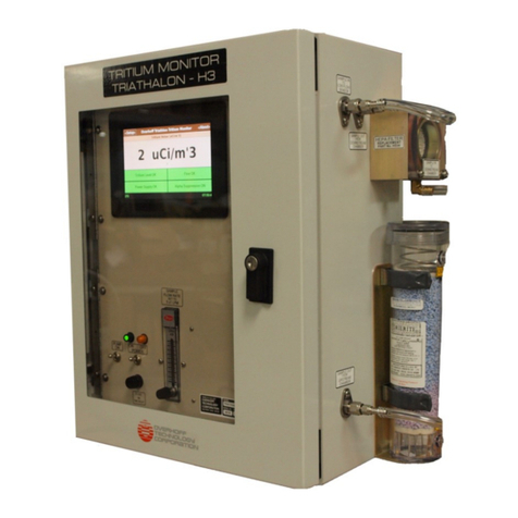
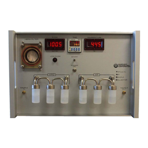
overhoff 357RM Manual

OPERATION/MAINTENANCE MANUAL
TRITIUM MONITOR
MODEL 357RM
OVERHOFF TECHNOLOGY CORPORATION
1160 US ROUTE 50, MILFORD, OHIO, USA

Operation and Maintenance Manual, Model 357RM Tritium Monitor, Serial No. 5075-76
REVISION INDEX
Rev Date Section/Page Details Appvd By
- 02-20-2019 Original Document DW

i
Tritium Monitor BETATEC Model 357 with dual 2 liter ionization chamber, single range, digital
display, radon alpha pulse suppression, single alarm system
TABLE OF CONTENTS
FIGURE 1, FRONT AND REAR PANELS........................................................................................1
1.0 GENERAL INFORMATION.................................................................................................2
1.1. INTRODUCTION
1.2. AVAILABLE CONFIGURATIONS
1.3. FEATURES .............................................................................................................3
1.4. GENERAL DESCRIPTION
1.5. RESPONSE OF IONIZATION CHAMBERS TO RADIATION
1.5.1. SPECIFIC IONIZATION CURRENT
1.5.2. THE WALL EFFECT........................................................................................4
1.5.3. RECOMBINATION EFFECTS
1.5.4. DISCRIMINATION AGAINST ALPHA PULSES..............................................5
1.6. CONTAMINATION (PLATE OUT) OF IONIZATION CHAMBERS
1.7. TECHNICAL SPECIFICATIONS
1.8. PERFORMANCE SPECIFICATIONS
1.8.1. MEASURMENT .............................................................................................6
1.8.2. ALARM SYSTEM
1.8.3. IONIZATION CHAMBER VOLUME
1.8.4. FLOWMETER................................................................................................7
1.8.5. DUST FILTER AND ELECTROSTATIC FILTER
1.8.6. PUMP
1.8.7. ENVIRONMENTAL TEMPERATURE
1.8.8. REAR PANEL INTERFACE
1.8.9. POWER
1.8.10. PHYSICAL
FIGURE 2, SAMPLE HOSE CONNECTIONS .................................................................................8
2.0. EQUIPMENT AND INSTALLATION....................................................................................9
2.1. EQUIPMENT SUPPLIED
2.2. INSTALLATION
2.2.1. PRECAUTION, SAMPLE FLOW SYSTEM .................................................10
2.3. OPERATION
2.3.1. INSTALLATION OF REMOTE OR ANCILLARY SYSTEMS
FIGURE 3, FUNCTIONAL BLOCK DIAGRAM...............................................................................11
3.0. INSTRUMENT ARCHITECTURE, DESCRIPTION...........................................................12
3.1. GENERAL
3.2. PENUMATIC
3.2.1. DUST FILTER
3.2.2. ION TRAP
3.2.3. IONIZATION CHAMBER
3.2.4. PUMP
3.3. CIRCUIT DESCRIPTION ......................................................................................13
3.3.1. IONIZATION CHAMBERS
3.3.2. ELECTROMETER
3.3.3. SIGNAL PROCESSING AMPLIFIER...........................................................14
3.3.4. ALARM CIRCUITS
3.3.5. POWER SUPPLIES

ii
4.0. CALIBRATION…………...............................................…………………………......…………15
4.1. FIRST METHOD, TRITIUM GAS CALIBRATION…………………………………..16
4.2. SECOND METHOD, GAMMA CALIBRATION
4.2.1. CALIBRATION VERIFICATION USING A SMALL GAMMA CHECK
SOURCE......................................................................................................17
4.3. THIRD MEHTOD - ELECTRICAL EQUIVALENCE METHOD
4.4 GAS METHOD, PRACTICAL PROCEDURE
4.4.1. DIRECT GAMMA CALIBRATION................................................................18
4.4.2. GAMMA VERIFICATION, USE OF CHECK SOURCE (PREFERRED
METHOD)
4.5. ELECTRICAL CALIBRATION, PRACTICAL PROCEDURE
FIGURE 4, CALIBRATION ADJUSTMENT………………................…………………………………19
4.6. EVIDENCE OF MALFUNCTION, PERIODIC CALIBRATION ..............................20
5.0 REPAIR AND TROUBLESHOOTING...............................................................................21
5.1. ELECTRICAL
5.2. MECHANICAL............................................................................................................22
6.0 MAINTENANCE ................................................................................................................23
6.1. OPERATOR MAINTENANCE
6.2. SUPERVISORY MAINTENANCE
6.3. FACTORY MAINTENANCE
7.0 STORAGE.........................................................................................................................24
8.0 WARRANTY......................................................................................................................25
9.0 DRAWINGS/DIAGRAMS...................................................................................................26
APPENDIX 1, MANUFACTURER’S DATA SHEETS
MEDO LINEAR POWERED DIAPHRAGM PUMP VCO-201
SOLBERG HEPA FILTER CARTRIDGE HE04
SELCO PANEL METER MODEL A9111-1


2
1.0. GENERAL INFORMATION
(see Figure 1, Front Panel)
1.1. INTRODUCTION
A tritium monitor is an instrument designed to determine the presence and level of radioactive gas
(tritium) in air or other gas streams. These monitors may be used to detect radioactive gases in
many applications like:
room air
stacks, hoods, or other effluent passages
process piping
glove boxes, and similar.
These monitors are generally calibrated in terms of (micro) Curies per cubic meter though other
units can be used as requested (Bequerel, pCi/cm3, etc.).
The principle of measurement is based on collecting the current that is generated by the radioactive
decay (of tritium) inside an ionization chamber. The ionization current is proportional to the
concentration of the gas radioactivity, as well as to the specific activity of the radionuclide (tritium)
being detected.
A tritium monitor consists of the following parts:
1. An ionization chamber to collect the ionization current.
2. A sampling system to circulate the sample (air) through the ionization chamber.
3. An electrometer to amplify the very weak ionization current.
4. All other associated electronics to process and display the signal.
Ionization chambers respond not only to the airborne radioisotope which circulates through the
ionization chamber, but also respond to the presence of external high energy radiation capable of
ionizing the air inside. Therefore, ionization chambers will respond to X-rays and gamma radiation
as well.
To overcome this effect, Overhoff Technology Corporation (OTC) tritium monitors can be supplied
with compensating ionization chambers. Here a second ionization chamber is used to cancel the
effects of external radiation upon the measuring ionization chamber. Additional gamma radiation
suppression can be accomplished by using lead shielding. OTC tritium monitors are equipped with
special circuitry to identify and reject ionization currents that are produced by decaying radon, or
other airborne alpha emitting radioisotopes.
1.2. AVAILABLE CONFIGURATIONS
OTC tritium monitors are available in a number of different configurations. Form and size depend
upon the application and use.
Portable instruments are battery powered and light weight.
Instruments used for fixed applications employ 19" rackmount enclosures which carry power
supplies and signal processing circuits. They may also contain the ionization chamber and
electrometer.
Ionization chambers and electrometers are available for remote installation where the "display"
enclosure is connected via a shielded ten conductor cable.

3
1.3. FEATURES
While the basic purpose of the OTC tritium monitor is to measure the presence and level of tritium
(or other airborne radioisotopes) the monitors may be supplied with a number of user selected
special features.
Your particular instrument, which is described in this manual, has these special features.
1. Ionization chambers with nominal volume of 2 liters each.
2. Single measurement range over four decades, with digital display.
3. Pump and flowmeter for sample transport.
1.4. GENERAL DESCRIPTION
This monitor consists of dual 2 liter ionization chamber with an integral electrometer coupled to the
electronic circuits in the display cabinet. The chambers are mounted internally in the cabinet. The
cabinet contains all signal processing, alarm and external interface circuits, read out, and all
required power supplies. The measurement ionization chamber serves to collect the current
produced as tritium decays radioactively. The second ionization chamber is identically constructed,
but sealed. It serves to cancel the effects of external gamma fields. The electrometer serves to
transform this current into a form and magnitude suitable for display, alarm, and external uses, as
the ionization current itself is very weak.
The signal processing circuits serve to reject unwanted signals and to translate the electrometer
signal voltage into a form and magnitude suitable for display, alarm and external uses as well.
The alarm circuits provide an acoustic signal to denote that a preset level of measurement has
been exceeded.
The purpose of the power supply needs no special comment.
1.5. RESPONSE OF IONIZATION CHAMBERS TO RADIATION
1.5.1. SPECIFIC IONIZATION CURRENT
The current generated in an ionization chamber is the result of collecting electrons generated from
ionization of gas caused by occurrence of a nuclear event in the gas inside.
The number of ions (magnitude of the current) is influenced by numerous factors like the energy,
physical nature and particle range. As a good rule of thumb for beta particles in air one secondary
electron (and one positive ion) is formed for every 34 electron volts of energy lost by the primary
beta particle as it travels its path.
The Curie is defined as 3.71 x 10¹⁰ nuclear decay events per second. The mean energy of tritium
decay is 5.69 kev. Therefore it is calculated that 1 Curie of tritium produces an ion current very
close to
1 x 10⁻⁶ Amperes
A concentration of 1 μCi/m3of tritium in a chamber of a volume of one liter will thus produce a
current of
1 x 10-15 Amperes

4
It must be remembered that the ionization chamber responds to the quantity of tritium present
inside. This is to say that effects due to temperature and pressure may need to be accounted for.
Even if a sample of gas is known to contain tritium at a certain concentration, i.e., parts per million
or other, it must be remembered that the activity (amount per unit volume) is dependent upon
temperature and pressure. The ionization chamber only responds to the quantity of radiation
inside.
1.5.2. THE WALL EFFECT
Ionization chambers also exhibit several other peculiarities. The wall effect can be a problem if the
track length of the decaying particle is appreciable when compared to the dimensions of the
chamber.
For ionization chambers with small linear dimension, and if the track of ionized particles is
comparatively long (the mean free path), an appreciable part of the energy of the primary particle
is simply dissipated in the wall of the ionization chamber. This effect increases as the chamber
dimensions shrink, and decreases as the chamber dimensions increase.
In air, atmospheric pressure, the maximum mean free path of a tritium beta particle is of the order
of five millimeters, and for chambers with linear dimensions of ten centimeters or greater this “wall”
effect becomes negligible.
1.5.3. RECOMBINATION EFFECTS
At high concentrations, another effect takes place.
When the ion population density is high, some of these positive and negative ions will recombine
and are lost to the measurement electrode.
This is known as saturation or stagnation since the effect is more pronounced in corners of the
ionization chamber where the potential field gradient is low. The effect can be reduced by
increasing the ionization chamber voltage.
For measurements of tritium at very high concentrations, such as are required when working with
pure T2, special chamber geometries are employed, long slender ionization chambers, with
relatively large internal ion collecting electrodes and short spacing between the chamber elements
enhance field gradients. With even moderate polarization potentials of 100 V or so, such chamber
geometries show linear response even to pure tritium streams.

5
1.5.4. DISCRIMINATION AGAINST ALPHA PULSES
Since the energy of an alpha decay is at least 10,000 times more active than that of a tritium beta
event, suppression of alpha pulses needed in order to distinguish the presence of tritium at low
levels. Stable and accurate measurements of tritium for values below 5μCi/m3can only be obtained
with means to suppress response to alpha decay.
Alpha decay events, as detected in an ionization chamber, are not instantaneous. The special
circuitry which recognizes the alpha pulses requires some amount of time to suppress the event.
During pulse suppression, the instrument analog circuitry is placed in a “holding” mode, response
is frozen during the interval associated with the alpha event. The holding intervals occur at random,
but effectively add to the apparent time constant of the electronics. The instrument response
becomes slower with increasing radon or gamma noise background. For large background the
instrument will even freeze completely, the alpha pulse light will be permanently illuminated.
1.6. CONTAMINATION (PLATE OUT) OF IONIZATION CHAMBERS
Tritium gas will combine with the oxygen and the moisture in the air to form oxide of tritium (HTO
or T2O). Chemically indistinguishable from normal water or watervapor, the tritium oxide will attach
itself to the walls of an ionization chamber and bond both physically as well as chemically.
1.7. TECHNICAL SPECIFICATIONS
The instrument described in this manual has been designed and constructed for your
particular application.
It has been built and tested to the specifications listed on the next pages.
Circuit diagrams and interconnections between parts of the monitor, as well as those leading to
user selected remote devices or interfaces, are given at the end of this manual.
Consult the factory for further information, or for application engineering
1160 US Route 50, P. O. Box 182
Milford, OH 45150-9705, USA
Telephone (513) 248-2400; Facsimile (513) 248-2402
www.Overhoff.com

6
1.8. PERFORMANCE SPECIFICATIONS
The following specifications will apply when this instrument is used for the measurement of tritium
1.8.1. MEASUREMENT
RANGES Tritium 1 – 19,999 μCi/m3
DISPLAY Digital Meter, 4 ½” digit LED
ACCURACY ±10 % of reading, ±1 μCi/m3, whichever is greater
STABILITY AND ±1 μCi/m3, ambient temperature, after warm-up
DRIFT LONG TERM
NOISE ±1μCi/m3, 2 sigma, with 20 second time constant
GAMMA second ionization chamber of equal volume, coaxially
COMPENSATION mounted, serves to cancel effects of external gamma fields
RESPONSE RATE two linear time constants
ELECTRONIC 20 seconds for measurements below approximately 80 μCi/m3
3 seconds for measurements above 80 μCi/m3
WARM-UP TIME less than 5 minutes
1.8.2. ALARM SYSTEM single alarm, with set point adjustable from 1 to 1,000 μCi/m3
INDICATORS acoustic signaller, red LED
MODE a. ON. Alarm will sound and can be reset
if the signal level recedes below the set point.
b. OFF. Alarm is inactive
c. RESET.
1.8.3. IONIZATION CHAMBER
VOLUME measuring: 1,600 cm3
total wetted: 2,000 cm3
ION TRAP Kanne Type, coaxial integral
ELECTRODES Screw-on barrel and 1/8” diameter rod with Teflon insulator
GASKETS silicone rubber
PRESSURE 0.1 to 2 atmospheres
PORTS 1/4" NPT, fitted with hose barb fittings for 3/16" I.D. vinyl tubing
MATERIALS OF all wetted surfaces, stainless steel
CONSTRUCTION

7
1.8.4. FLOWMETER 0-10 LPM adjustable rotameter
1.8.5. DUST FILTER high efficiency 99.99% at 0.1 microns, respirator type filter
cartridge Solberg Manufacturing Product No. HE04
1.8.6. PUMP long life continuous duty oscillating piston positive
displacement pump. Medo Model VCO201E1 for 115VAC
1.8.7. ENVIRONMENTAL storage: -40°C to +60°C
TEMPERATURE operating: 0°C to +50°C
HUMIDITY 0 to 95 % R.H.
1.8.8. REAR PANEL see wire lists at end of manual
INTERFACE
SCREW TERMINALS linear signal output
CONNECTIONS alarm relay contacts
1.8.9. POWER 115 VAC, 50/60 Hz, 35 W maximum
FUSE 1.0 A, slow blow, .25" diameter x 1.25" long
1.8.10. PHYSICAL
CABINET 19 “ rack mount, frame constructed of aluminum extrusions, front and
rear panel are 1/8” thick aluminum. Covers are aluminum sheet.
DIMENSIONS 8.75” H x 19.00” W x 16.00” D
WEIGHT 35lbs.


9
2.0. EQUIPMENT AND INSTALLATION
2.1. EQUIPMENT SUPPLIED
1. Cabinet containing filter, flowmeter and pump, plus all associated electronics, displays and
ionization chamber/electrometer assembly
2. Detachable AC line cord, 10ft (3m) long
3. Manual in printed and electronic (CD-ROM) formats.
2.2. INSTALLATION
NOTE: NOT SUITABLE FOR USE IN A WET LOCATION. NOT SUITABLE FOR USE IN
EXPLOSION HAZARD ENVIRONMENTS
The following information is provided to the user to ensure stable and accurate performance.
The cabinet can be located on any flat surface, such as a table top, or, it can be mounted to a wall
bracket, or on a small moveable cart. In all cases, the instrument must be protected against
vibration, shock, moisture and dirt.
Gamma compensation of this instrument has been designed to correct for normal terrestrial
background, and small artificial gamma background. In the event that the instrument is to be used
in the presence of somewhat higher gamma background, the user may wish to construct a lead
shield to reduce radiation incident upon the monitor. Of course, there is provision for the instrument
to be used for the direct measurement of gamma. In this instance, the pump should be turned off,
after first flushing the sampling system with radio-logically clean air.
ELECTRICAL GROUNDING
The electrical and electronic equipment grounding is often considered only form the viewpoint of
hazard and safety. Indiscriminate or excessive grounding may actually enhance the potential of
danger and disturb the proper internal operation of the instrument. The electronic circuitry, including
logic, adjustment controls, and local and remote displays, are centrally and all inclusively grounded
at the ionization chamber module. The circuit system common line is electrically connected to the
metal frame or housing of the electrometer module. When signal outputs are connected to remote
displays, computer interfaces, or similar devices, it is necessary that no significant ground potential
differences exist between the monitor and other equipment. If significant potential ac or dc
differences exist, shifts in the instrument “zero” can appear.
THE FOLLOWING IS RECOMMENDED:
1. Make all interconnections. The AC power shall be connected using the flexible line cord
provided. Activate total instrument. Allow ten minute “warm-up”. Adjust zero if needed.
2. Attach remote connections (devices) and verify absence of change in zero.
If the zero has changed, check for ground loops and spurious ac or dc potential differences from
one location to the other.
Select a site for the instrument, turn off the main power switch and the switch for the pump.
Attach all remote equipment with the wiring as supplied by OTC, or as designed locally for interface
or remote alarms. Refer to 2.3.1. for important information.
CAUTION: Do NOT replace the supply cord with an improperly rated one, for additional
information, refer to the Safety Notice at the beginning of this manual

10
2.2.1. PRECAUTION, SAMPLE FLOW SYSTEM
A high efficiency dust filter must always be installed at the input of the measuring
ionization chamber. Failure to include a dust filter will cause debris build-up in the
ion trap and the monitor will behave erratically. Monitors placed into lines
carrying pure dust free process gases are an exception to the dust filter rule.
A flow rate of 3 to 6 liters per minute is recommended for 2 liter ionization chambers.
Too low a flow rate causes sluggish response. Too high flow rates induce significant
pressure changes within the ionization chamber, which shifts it out of proper calibration.
2.3. OPERATION
After ensuring that the instrument is installed, and that the pneumatic system is checked,
all in conformance to the preceding instructions, the following steps are suggested.
1. Locate and turn OFF the main power switch.
2. Locate and turn OFF the pump ON/OFF switch.
3. Select the OFF position of the alarm mode toggle switch.
4. Adjust the alarm level to full scale.
5. Select active mode for noise suppression
6. Attach mains line cord
7. Turn mains power switch ON.
8. Warm up one minute minimum. Adjust the compensation potentiometer to obtain a ZERO
reading on the meter.
9. Adjust the alarm set point potentiometer.
10. Switch the alarm mode toggle to the ON position.
11. Allow instrument to settle for up to ten minutes.
12. Activate the pump, set flow meter needle valve for desired flow rate (typically 3 to 6 liters per
minute).
13. Instrument is now in service.
2.3.1. INSTALLATION OF REMOTE OR ANCILLARY SYSTEMS
A 6 position screw terminal block is located at the rear of the cabinet. This carries many connections
for remote meter display alarm relay contacts. A wire list for these connections is given at the
manual's end.
These connections can be made prior to placing the monitor into active duty.
WARNING: CARE MUST BE TAKEN NOT TO CREATE GROUND LOOPS. THE SIGNAL
CIRCUIT COMMON OF THE MONITOR IS ELECTRICALLY CONNECTED TO THE
FRAME OF THE IONIZATION CHAMBER.
The relay contacts are rated at 0.25 amps, 100VDC or 60VAC. The alarm relay operates in the
failsafe mode. The relay coil is energized with the instrument in a “NO ALARM” state.
NOTE: THE ALARM RELAY CONTACTS ARE FULLY ISOLATED.


12
3.0. INSTRUMENT ARCHITECTURE, DESCRIPTION
3.1. GENERAL
This section contains a simplified basic description of the functioning of the individual components
of this monitor. The description is provided as background information for the user, engineer, or
technician responsible for service and calibration.
3.2. PNEUMATIC
The pneumatic system of the monitor is comprised of the dust filter, ionization chamber and
upstream pump.
3.2.1. DUST FILTER
A high efficiency particulate air (HEPA) filter should be used in order to reduce pressure drops to
practical minimums. This type of filter acts to remove particulates and ions to a high degree of
efficiency. Large particles are removed mechanically. Small particles and ions are removed
electrokinetically through triboelectric action.
3.2.2. IONIZATION CHAMBER
The ionization chamber serves to segregate the positive and negative charges arising from nuclear
decay. In principle, the current collected by the ion (or electron) collecting electrode is linearly
proportional at the transducer, to the gas activity.
The wall of the measurement chamber is at a negative potential with respect to the collecting rod.
The wall attracts positive ions and the collecting rod collects electrons. The ionization chamber, the
collecting rod and the electrometer preamplifier are mechanically rigid and massively designed so
that microphonic and piezo-electric effects are minimized. These effects disturb proper alpha pulse
detection.
3.2.3. PUMP
The pump is located upstream of the ionization chamber. It has been selected to produce a flow
sufficient to meet the pneumatic response rate requirements. Excessively large flow rates should
be avoided since they may lead to appreciable pressure drops in the ionization chamber with a
consequent loss in accuracy of measurement. Too low a flow rate will result in sluggish response.

13
3.3. CIRCUIT DESCRIPTION
CAUTION: This instrument has not been designed for indiscriminate opening or disassembly
of the internal parts. It contains highly sensitive semiconductors which are damaged
by even the slightest electrostatic discharge.
3.3.1. IONIZATION CHAMBERS
In its simplest form, an ionization chamber is an enclosed volume with two electrodes. Voltage is
applied between the electrodes, generating an electric field which will segregate and collect electric
charges which are created by nuclear events occurring inside the chambers. Nuclear events may
consist of ionization of air molecules by external or internal alpha, beta or gamma radiation.
The OTC monitors are designed to measure tritium. Activity of tritium decay is such that a
concentration of 1 μCi/m3in a volume of 1 liter will generate an ionization current of about 10-15
amperes. This is a very weak current.
Alpha pulses from naturally occurring radon, are much more energetic. They can produce short
current bursts of up to 10-13 coulombs during decay, and therefore appear as large noise “spikes”
which can seriously impair tritium measurement.
Gamma radiation also has a strong effect. In an ionization chamber, in air, a gamma radiation field
of 1 mr/hr will create the same amount of ionization as 90 μCi/m3of tritium.
A tritium monitor, in order to measure to low concentrations, should respond only to tritium and be
immune to alpha or gamma radiation. For this purpose, a second ionization chamber system has
been included to balance out any ionization current contribution from external gamma radiation.
In the 357 series instrument, the two ionization chambers are arrayed coaxially ensuring good
gamma compensation in all directions especially for fields incident perpendicular to the chamber
axis.
Approximately two hundred volts polarizing potential is supplied to the ionization chambers. A
negative voltage is applied to the measurement chamber, and a positive voltage of equal amplitude
is applied to the compensation chamber.
3.3.2. ELECTROMETER
Also known as a transimpedance amplifier, it serves the purpose of converting the extremely feeble
ionization current into a voltage suitable for further signal processing and measurement display.
The heart of the electrometer consists of a specially selected ultra high impedance semiconductor
device which has been chosen both for ultra low internal current leakage as well as long term D.C.
stability. the semiconductors used in the 357 instrument are suitable for measurement of currents
as low as 10-16 amperes.
In all 300 series instruments, the electrometer is directly attached to the ionization chamber pair
and is protected by solid metal. This configuration helps to reduce effects from vibration.

14
3.3.3. SIGNAL PROCESSING AMPLIFIER
The signal processing amplifier converts the output of the electrometer signal into a 0 - 10 V signal
for driving the panel meter, the alarm system and remote signal outputs.
Proprietary circuitry is used for the recognition and elimination of transient signals due to alpha
pulses generated by radon decay or due to passage of high energy cosmic rays. The noise
suppression ACTIVE toggle switch controls this circuit. The LED signals when the circuit has
detected an alpha pulse and the main amplifier is in a hold mode.
In addition this circuitry is active only on the low (1 – 80μCi/m3) measurements, and is automatically
disabled on higher levels in order to increase speed of response where it is most needed. The
electronic time constant is typically 20 seconds (or less) for the low level measurements, but drops
to 2 seconds or less for higher levels.
The front panel COMPENSATION control is provided to trim an offset.
3.3.4. ALARM CIRCUITS
This monitor is equipped with a single independent signal alarm. The set point can be set for
any value 0 – 1000 μCi/m3by means of a ten turn potentiometer located on the front panel.
SIGNAL ALARM
1. The signal alarm activates an acoustic signal.
2. The alarm may be switched ON or OFF.
3. The alarm will continue to operate until manually reset, even if the displayed signal has receded
below the set point.
4. The alarm has relay interface connections on the terminal block at the rear of the cabinet.
3.3.5. POWER SUPPLIES
All power supplies are fully regulated. Low voltage (±15 V) supplies are used through out to power
the semiconductor circuitry. The polarization potential for the ionization chambers, nominally ±140
V are fully regulated, noise and ripple free.

15
4.0. CALIBRATION
INTRODUCTION
Calibration (or verification) of tritium monitors can be accomplished by three different methods. The
object is to make sure that the instrument displays reading which correctly corresponds to the
activity of the tritium laden gas stream passing through the ionization chamber.
Each method has advantages and disadvantages.
The direct method involves the introduction of tritium in an exactly known concentration and
adjusting the monitor to read correctly. The second method, is to expose the ionization chamber
to a gamma flux of known (repeatable) intensity. The third method is to simulate the ionization
current by introducing a known electric current directly into the electrometer.
The tritium monitors are brought into proper calibration by adjustment of trimmer potentiometers
included for this specific purpose.
Most of the OTC tritium monitors can be calibrated directly at the ionization chamber electrometer
module. The trimmer potentiometers are located in a pocket in one side of the electrometer
housing, and are usually covered with a plastic or metal plate to prevent unauthorized manipulation.
FIRST METHOD
To ensure traceability to National Standards, the first method is generally mandated by government
authorities. This method is time consuming, and is quite difficult to perform with precision. This
method is, however, useful as a “type” test, and can serve as a basic accurate calibration from
which the gamma response (the second method) can be cross correlated.
SECOND METHOD
Uses an external gamma field, a field strength of 1 mr/h should produce a meter reading of 90 μCi/m3.
A standard instrumentation calibration gamma range facilities can be used.
THIRD METHOD
All OTC ionization chamber - electrometer modules carry a BNC receptacle to which a precisely
calibrated ultra high resistor can be attached. Using Ohm’s law, and knowing the volume of the
ionization chamber, a voltage value can be calculated for a properly simulated ionization current.

16
4.1. FIRST METHOD, TRITIUM GAS CALIBRATION
The first method involves the injection of tritium into the ionization chambers in an amount that will
produce an accurately predictable concentration. The tritium monitor calibration potentiometer is
then adjusted to make the measurement display coincide with the predicted gas concentration.
In order to do this, one needs a source of tritium gas with a known activity and knowledge of
effective volumes of ionization chambers and all other volumes involved.
Gas sources are normally found to be tritium gas calibrators (consisting of a lecture bottle filled with
tritiated methane at a known activity, plus pressure regulators, valves and an accurately known
sample chamber). The calibrator enables one to inject tritium at a calculated activity into a loop
comprising the ionization chamber and calibrator.
Documentation furnished with the calibrator will provide data concerning the STP activity of the
bottled gas.
This is the activity in Curies (or milliCuries) of 1 cubic centimeter of gas at a standard pressure of
760 Hg at 0º C.
Instructions with detailed procedure for use are supplied with gas calibrators. A table for the
determination of decay factors is usually included. The half life of tritium is about 12.33 years.
Some general hints can be given.
It is important that the calibration sample be well circulated through the entire calibration system
loop.
Adequate time should be allowed for the system pressure and temperature to come to equilibrium,
and that no excess pressure is built up.
The inclusion of a previously calibrated “master” or “reference” tritium monitor the sampling loop is
highly recommended.
The calibration can actually be repeated for several levels of tritium activity. This is not done in
order to verify the linearity of the tritium monitor (which is highly linear) but to ensure that the
calibration process itself is free from subtle errors.
If several monitors all require calibration, it is permissible to connect them all at once in a loop.
4.2. SECOND METHOD, GAMMA CALIBRATION
Ionization chambers are often used for direct gamma detection and measurement. The ionization
chambers used for the measurement of radioactive gases are similarly sensitive to gamma
radiation.
With access to a certified gamma range, calibration facility, tritium monitors can be calibrated using
the relationship:
1 mr/hr yields the same ionization current as 90 μCi/m3of tritium.
For calibration purposes, the center of a standard 2 liter ionization chamber is located 9 cm forward
of the rear of the cabinet. The distance may be verified by removing the top cover of the monitor
and measuring the precise distance.
Table of contents
Other overhoff Laboratory Equipment manuals
Popular Laboratory Equipment manuals by other brands

Techne
Techne TC-412 Operator's manual

Leica
Leica HI1210 Instructions for use

DLAB Laboratory Instruments
DLAB Laboratory Instruments DM0412S user manual

Elster Instromet
Elster Instromet EnCal 3000 Quad Hardware manual

Kendro
Kendro HERAcell 150 operating instructions

Waters
Waters Vion IMS QTof Overview and maintenance guide

Saniswiss
Saniswiss biosanitizer automate user manual

Civco
Civco GUS G10VPL Operator's manual

MMR Technologies
MMR Technologies elan2 digital user manual

Renfert
Renfert Basic Master Translation of the original instructions for use

Hach
Hach LQV157.99.50001 User instructions

Kinematics
Kinematics 4400/PVC operating instructions