Overland Storage SnapServer 2U Appliance User manual

ARCvault
10400196-102 03/2009 ©2009 Overland Storage, Inc. W1
Series
ARC-0203
2U Bulkhead & Cable Assembly
Remove & Replace Instructions
Overview and Notes
IMPORTANT: Overland Storage requires that all ARCvault parts in this procedure be
removed and replaced by an Overland Storage authorized service provider. Improper
installation can result in damage which voids existing warranties.
This document describes how to remove and replace the front bulkhead and flex cable
assembly in an ARCvault 2U library or loader from Overland. This is only for units with
a serial number 2B73400000 or higher.
WARNING: To reduce the risk of electric shock or damage to equipment, remove the
power cord before working on the unit.
Unpacking
Carefully unpack and verify that you have all the parts:
•2U bulkhead & cable assembly in anti-static bag
•These remove & replace instructions
•9 bags of screws and washers consisting of:
A magnetic #1 Phillips screwdriver, flatblade screwdriver, flashlight, and 2.0mm hex
driver are also needed.
Electrostatic Discharge Information
A discharge of static electricity can damage micro-circuitry or static-sensitive devices. To
help prevent Electrostatic Discharge (ESD), observe standard ESD precautions.
Bag # Quantity Size Description
1 2 4-20x1/2 inch Panhead screw
2 2 4-20x5/16 inch Panhead screw
3 2 6-32x1/4 inch Panhead Phillips screw
4 2 M3x5mm Buttonhead hex screw
5 20 M3x6mm Flathead screw
6 1 M3x8mm Buttonhead hex screw
7 2 M3x10mm Flathead screw
8 2 M3x14mm Panhead Phillips screw
93M3 Cupwasher
10400196-102 03/2009 ©2009 Overland Storage, Inc. W2
2U Bulkhead & Cable Assembly ARCvault Series R&R Instructions
Removing the Old Assembly
All positions stated are relative to standing in front of the library (left, right, etc.). New
screws and washers are provided for all the removed items but you may want to retain the
old hardware in the large plastic bag. When you are done, discard the old hardware.
Remove Unit from Rack
WARNING: It is recommended that a mechanical lifter (or at least two people) be used to
prevent injury during rack removal or installation.
1. At the rear of the unit, remove the power cord and all cables.
2. Inside the front doors, loosen the retaining screws.
3. Using either a mechanical lifter or at least two people, remove the ARCvault unit
from the rack and place it on a secure, flat ESD surface.
Remove the Covers
1. Remove the six screws from the front top cover and set the cover aside.
2. Remove the eight screws from the rear top cover and set the cover aside.
Remove the Magazines
CAUTION: Always keep a loaded magazine level to prevent the tapes from falling out. Also,
don’t hold a magazine by just the handle; use both hands to support it.
1. For the right magazine:
a. Open the magazine door.
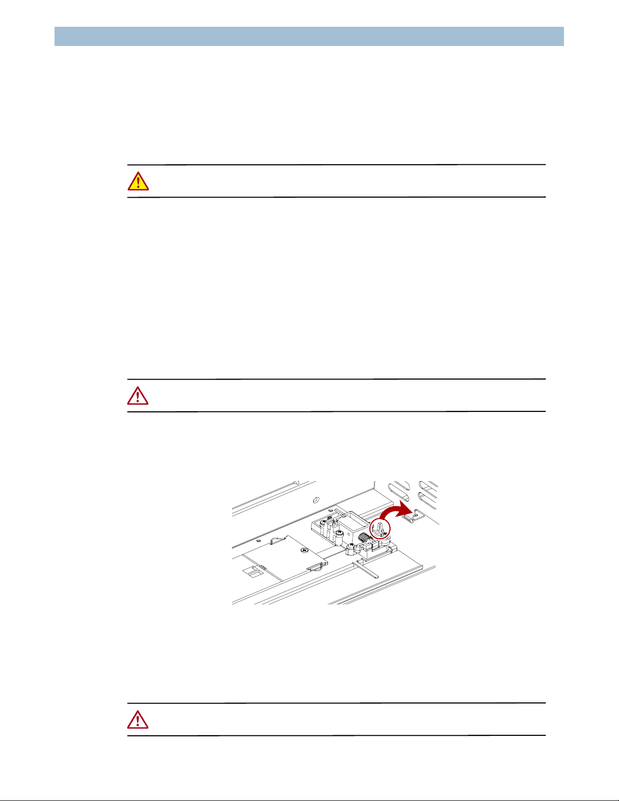
b. Release the solenoid latch (Figure 1) at the rear of the magazine.
Figure 1: Swing Solenoid Latch Release Handle Toward Rear
c. Carefully slide the magazine out.
2. For an ARCvault 24, repeat Step 1 for the left magazine.
Remove the Trackplate
CAUTION: If the trackplate is raised, removing the vertical motor causes it to quickly
descend. Support it as you disconnect the motor and then lower it slowly.

10400196-102 03/2009 ©2009 Overland Storage, Inc. W3
2U Bulkhead & Cable Assembly ARCvault Series R&R Instructions
1. At the rear of the trackplate, remove the vertical motor by removing the two
bracket screws and washers (Figure 2), and set the motor aside in the area of the
removed magazine.
Be careful not to damage the wiring connected to the rear of the motor.
Figure 2: Vertical Motor Bracket Screws
2. At the front of the trackplate, remove the hexhead screw and washer (Figure 3)
securing the Spring Assembly post.
Figure 3: Front Trackplate Components (Viewed From Rear)
3. Remove the motor cable (and any Kapton tape) from the front motor socket.
4. Remove the flex cable from the shuttle:
a. Carefully remove the two cable bracket screws on the side of the shuttle
(Figure 4).
Figure 4: Shuttle Screw Locations
Bracket Screws & Washers
Motor Cable Spring Assembly Post
Hexhead Screw and Washer
Motor Socket
ARC-0111
Cable
Bracket
Remove
Screws
Bracket
Shuttle Front
(Open End)
10400196-102 03/2009 ©2009 Overland Storage, Inc. W4
2U Bulkhead & Cable Assembly ARCvault Series R&R Instructions
b. Unplug the Signal and Power cables from their sockets (Figure 5).
Figure 5: Flex Cable Connections on Shuttle
To remove the cables, press the release tabs on the outside of the plugs (see
arrows in diagram) and gently pull the plugs.
5. Remove the trackplate (with shuttle still attached):
a. Lift the trackplate halfway up.
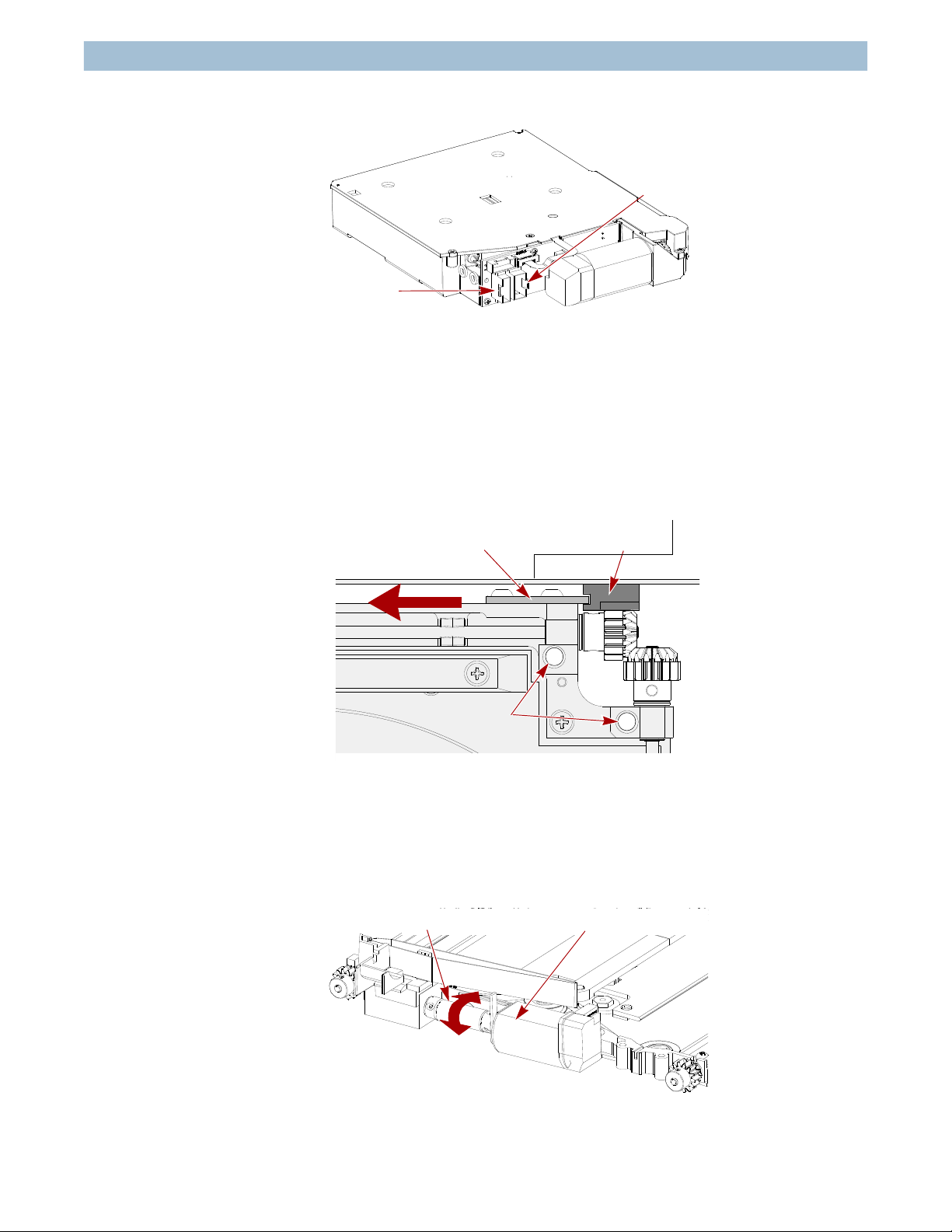
b. Slide the rear of the trackplate to the left to release the alignment tab behind
the right rear vertical gear rack (Figure 6) and the rear gears.
Figure 6: Release Trackplate Rear Tab (Top View)
c. Raise the trackplate rear to lift it up and out, disengaging the front gears.
d. Set the trackplate on a secure surface.
6. Using your finger, roll the coupling tube (Figure 7) to move the shuttle toward the
rear until it just reaches the rear belt roller guides (Figure 33 on page 15).
Figure 7: Rotate Coupling Tube Located on Trackplate Front
ARC-0112
Power Cable
Socket
Signal Cables
Socket
Right Rear
Rear Alignment Tab
Front Motor
Bracket Holes
Gear Rack
Coupling Tube Shuttle Motor

10400196-102 03/2009 ©2009 Overland Storage, Inc. W5
2U Bulkhead & Cable Assembly ARCvault Series R&R Instructions
NOTE: If the shuttle is on the right side of the trackplate, roll the tube AWAY from the front;
otherwise, roll the tube TOWARD the front.
Remove the Power Supply
1. At the rear, remove the two panhead screws holding the power supply (Figure 8).
Figure 8: Remove Power Supply Screws
2. On the outer side of the chassis, remove the flathead screw holding the bracket
(Figure 8).
3. Holding the power supply, remove the flathead screw on top of the inner chassis
wall (Figure 8) holding the bracket.
4. Still holding the power supply, remove it as follows:
a. Move it forward about an inch until the rear releases.
b. Simultaneously lift up and swing the rear end toward the center, freeing the
bracket.
c. Set the power supply on top of the drive without putting a strain on the cables.
Check Controller Card
In some cases, the F4, F5, or F6 fuse on the Controller card may also be blown and the card
needs to be replaced.
1. Locate the fuses (Figure 9) on the Controller card.
Figure 9: Location of Fuses on Controller Card
ARC-0200
(1) Remove Screws
(2) Remove Side Screw
(3) Remove Screw
Bracket
ARC-0210
Front Edge
Check These Fuses
F6
F4
F5

10400196-102 03/2009 ©2009 Overland Storage, Inc. W6
2U Bulkhead & Cable Assembly ARCvault Series R&R Instructions
2. Using a Volt-Ohm meter, check the continuity of the fuses.
3. If one or more is bad, replace the board using an ARCvault Series 2U Controller
Card spare kit before continuing with this installation.
Disconnect Controller Cables
1. Raise the cable clamp at the front of cavity next to the cable access hole
(Figure 10).
Figure 10: Controller Card Cables
2. Press the top tab to release (in order) connectors J9, J12, and J17.
3. Squeeze the connector sides to release J16.
4. Gently pull the connector straight out to remove J18.
5. Carefully pull the five released cables out of the cable access hole.
6. Carefully raise all four cable tray tabs no more than 45º (Figure 11) to release the
cables.
Figure 11: Raise the Cable Tray Tabs Halfway
7. Remove all cables and the top two Electromagnetic Compatibility (EMC) strips
from the cable tray. Leave the bottom EMC strip in the tray.
J9
J12
J17
J16
J18
Cable Clamp
Cable
Access Hole
Cable
Tray Tab
Chassis
Rear
(Raise Up)
C-0209
Tray Tabs
Raise Each to 45º Angle
10400196-102 03/2009 ©2009 Overland Storage, Inc. W7
2U Bulkhead & Cable Assembly ARCvault Series R&R Instructions
Remove Old Bulkhead Assembly
CAUTION: Do not turn the ARCvault unit on it’s side or upside down. Do not put pressure on
the door edges.
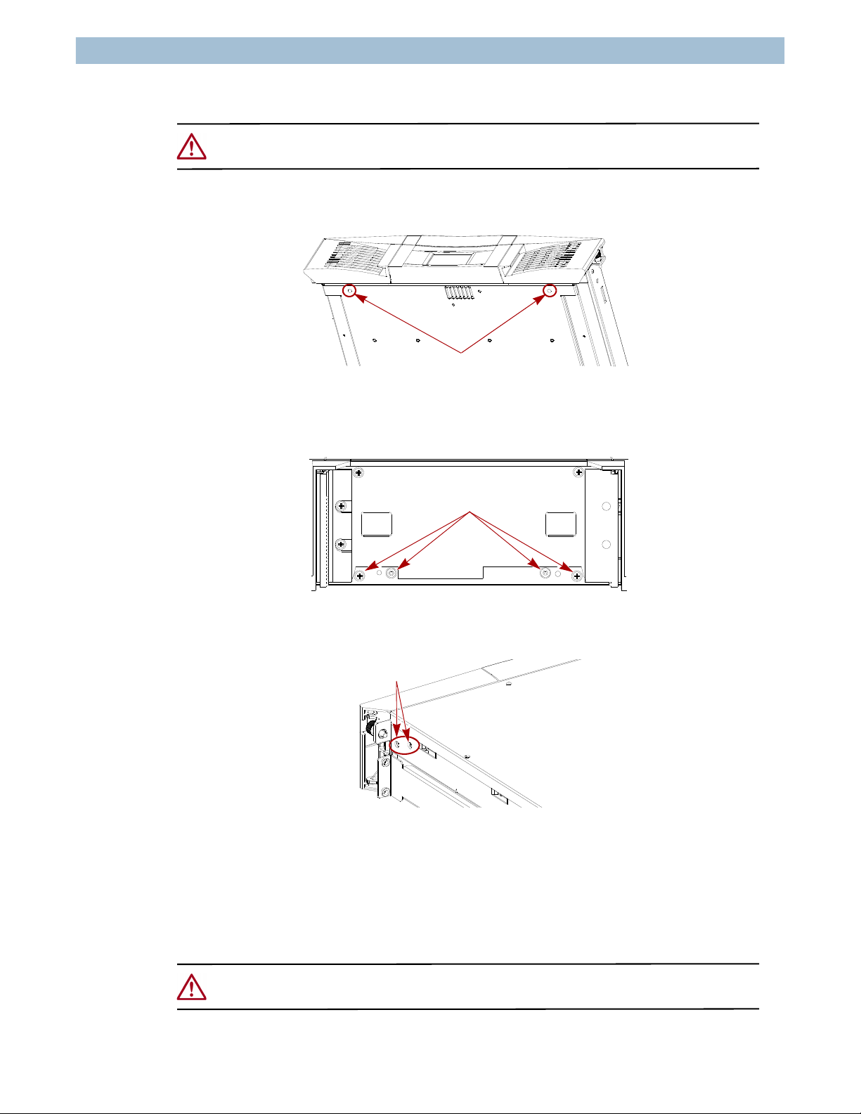
1. Slide the front of the unit off the table and remove the two bulkhead screws
underneath the chassis centered beneath the doors (Figure 12).
Figure 12: Bottom Bulkhead Screws
2. Remove the four inside screws (2 Phillips and 2 hexhead) holding the bulkhead to
the chassis (Figure 13).
Figure 13: Inside View of Front Center Bulkhead
3. Remove the four bulkhead screws, two on each side of the chassis (Figure 14).
Figure 14: Bulkhead Side Screws (Right Side)
4. Tilt the top of the bulkhead out to a 45º angle, lift the bulkhead off the front edge of
the chassis, and set the bulkhead and cable assembly aside.
Installing the New Assembly
CAUTION: Do not loosen the screws securing the two front vertical gear racks to the new
bulkhead. They are factory aligned.
ARC-0202
Remove Screws
ARC-0199
Remove Screws
Remove Screws

10400196-102 03/2009 ©2009 Overland Storage, Inc. W8
2U Bulkhead & Cable Assembly ARCvault Series R&R Instructions
Install the New Bulkhead
1. Cut the three red-tipped cable ties holding the flex cable shuttle bracket
(Figure 15) against the bulkhead.
IMPORTANT: Be careful not to damage the flex cables while cutting the cable ties. Cut
away from the flex cables.
Figure 15: Remove Flex Cable Ties
2. Gently lay the flex cable assembly over the bulkhead and outside of the chassis.
CAUTION: Do NOT put stress on the cable, twist it, or catch it against any sharp
objects.
3. Attach the new bulkhead to the chassis:
a. Holding the new bulkhead at the front of the chassis, remove the tape holding
the bulkhead cables inside the left door (Figure 16).
Figure 16: Remove Tape from Bulkhead Cable Bundle
Carefully Cut
These Ties
Remove Tape

10400196-102 03/2009 ©2009 Overland Storage, Inc. W9
2U Bulkhead & Cable Assembly ARCvault Series R&R Instructions
b. Lay the bulkhead cables over the cable tray (Figure 17) and leave loose.
Figure 17: Lay Bulkhead Cables Over the Cable Tray
CAUTION: Make sure that the cables stay in their original positions under the
bulkhead and that they do not catch on the chassis when the bulkhead is
inserted.
c. Holding the bulkhead at a 45º angle, hook the bulkhead groove under each door
onto the chassis edge (Figure 18).
Figure 18: Hook Groove Onto Chassis Edge
d. Swing up the bulkhead top inserting the two side tabs into the chassis slots.
CAUTION: To prevent stripping a screw, do not tighten any bulkhead screws until ALL
the screws are installed.
Cable Tray
Bulkhead Groove
Side Tab

10400196-102 03/2009 ©2009 Overland Storage, Inc. W10
2U Bulkhead & Cable Assembly ARCvault Series R&R Instructions
4. Loosely install two new M3x5mm hexhead (Bag 4) screws inside at the bottom of
the bulkhead (Figure 19) in the inside holes.
Figure 19: Install Inside Bulkhead Screws
5. Loosely install two new Phillips 4-20x1/2 panhead (Bag 1) screws inside the
bulkhead in the outside holes (Figure 19).
6. Loosely install four new M3x6mm flathead screws (Bag 5), two on each side of
the chassis (Figure 20).
Figure 20: Bulkhead Side Screws (Right Side View)
7. With the front edge off the table, loosely install two new M3x10mm flathead
screws (Bag 7) under the doors (Figure 21).
CAUTION: Do not turn the ARCvault unit on it’s side or upside down. Do not put
pressure on the door edges.
Figure 21: Bottom Bulkhead Screws
8. Gently tighten (about 6 lbs. torque) all bulkhead screws in the order they were
installed.
ARC-0199
Phillips
Leave Empty Leave Empty
Hexhead
Install Screws
ARC-0202
Install M3x10mm Screws
Other manuals for SnapServer 2U Appliance
1
Table of contents
Other Overland Storage Cables And Connectors manuals


