Installing the Rails
1
1
1
2
2
3
3
4
1Clip Nut
2Tapped Vertical Member
Mounting Holes
3Untapped Vertical Member
Mounting Holes (10-32
Clearance)
4Middle Slide Member
neo-003
3
2
1
1Clip Nut
2Middle Slide Member
3Inner Slide Member
1. Attach the shorter front 1and longer rear 2mounting brackets to
the outer and middle slide members 3.
2. Make sure you have adequate space available in the rack.
3. Mark the attachment points for the mounting brackets on the rack’s
front and back vertical rails using the supplied mounting template.
IMPORTANT: Fully tighten the front mounting bracket screws. Leave the
rear mounting bracket screws “finger tight” to prevent binding when
mounting the library.
4. Attach the slide members using the supplied fasteners. Install clip nuts 1on
the inside of the slide member’s front and back mounting brackets only if the
vertical rail mounting holes are not tapped.
5. Push the middle slide member 4as far as possible to the front of the slide
member assembly.
WARNING: Use a mechanical lift to perform the next step. Make cer-
tain, when the library is fully extended, that a force of 20% of the
racks’s weight, but not more than 57 lb. (26 Kg), applied in any direc-
tion other than upwards, does not cause the rack to overbalance.
1. Mark the attachment points for the library retaining screws using the
supplied mounting template.
2. Install the two clip nuts on each of the rack’s front vertical rails.
3. Lift the library and visually align the inner and middle slide members.
4. Carefully insert the library’s inner slide members into the middle slide
members.
5. Slide the library completely into the rack until the front panel touches it.
6. Fully tighten the rear mounting bracket screws.
WARNING: A Storage cabinet might become unstable if more
than one component is extended for any reason. Extend only one
module at a time.
CAUTION: The library module is heavier toward the tape drive
end (rear). The library can be made lighter by removing the tape
drive(s) prior to rack mount installation.
Installing the Library Module
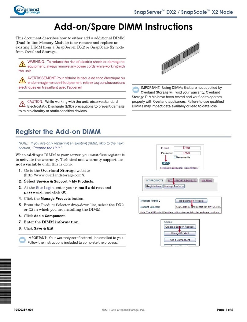
2Opening Magazine Doors
3Securing LIbrary Module
4
1 Left Side Retaining Screw
2 Right Side Retaining Screw
With the magazine doors open, secure the front panel to the storage cabinet
using the two retaining screws. Close the doors before proceeding to Step 5.
Neo-9129
LXN 4000
Template Size
LXN 2000
Template Size
Use the template shipped with the library to mark the location of the mount-
ing hardware on the mounting rails of the storage cabinet.
1. Push back the tabs in the top of the template and place them in the
correct holes in the mounting rack. Match up the hole pattern indicated
on the sides of the template with the hole pattern in the mounting rack.
2. Make sure to begin measuring in the correct place. If a module already
installed immediately below the planned position of the new module,
place the template against the front of the mounting rack and rest it on
top of the previously installed module.
3. Use the front of the template to mark the attachment points for mount-
ing brackets, rails, components, or cage nuts on the back of the storage
cabinet.
4. Use the back of the template to mark he attachment points for mount-
ing brackets, rails, components, or cage nuts on the back of the storage
cabinet.
5. Remove the template, then attach the rails using the supplied fasten-
ers.
Neo-9130a
3
12
31 2
1 Left Emergency Door Release
2 Library Status LED
3 Right Emergency Door Release
Remove the tape to open the doors for installation. Remove and discard the
pull-tabs used to block the latch mechanism before closing the magazine doors.
Leave the doors open and proceed to Step 4.
IMPORTANT: The magazine doors have both and electrical release (via the GUI
touch screen) and a manual release. It is recommended that the doors always
be opened using the GUI touch screen when ever possible. In an emergency, the
doors can be manually opened by pushing a paper clip into the mechanical
releases.
Powering LIbrary Module
5
Neo-9127
2
3
1
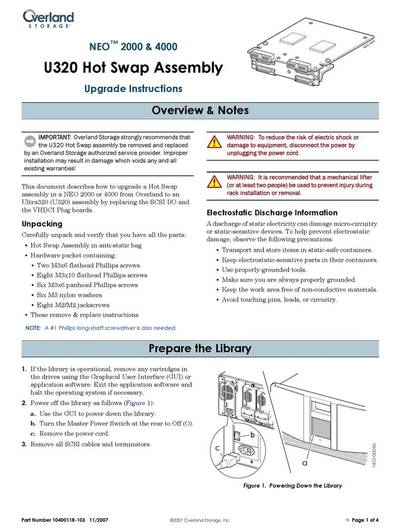
1. Connect each supplied power cord 1to each power supply receptacle.
2. Toggle each power switch 2on.
3. Press anywhere on the GUI touch screen 3to activate the display and
turn the library module on.
NOTE: NEO library modules support 1 to 4 hosts and1 to t tape drives. Con-
tact you Overland Authorized Reseller for a complete list of supported config-
urations.
Neo-9131
2
1
2
1
Cabling the Library Module
6
Neo-9034
4
1
32
Neo-9133
1
2
3
3
5
4
Two Drives,
Single Host
1SCSI Terminator 2To Library Controller Card
3Jumper Cable 4To Host
IMPORTANT: The short jumper cable 3is designed specifically for this
use only. Stretching it to reach the library controller card can damage the
cable. Use the supplied cable 2to connect the tape drive and library con-
troller card.
NOTE: Host cables are not supplied. Refer to the Neo Series Installation
and User manual for complete configuration and operation information.
Two Drives,
Single Host
1SCSI Terminator 2To Library Controller Card
3Short Jumper Cable 4Long Jumper Cable
5To Host
IMPORTANT: The short jumper cable 3is designed specifically for this
use only. Stretching it to reach the library controller card can damage the
cable. Use the supplied cable 2to connect the tape drive and library con-
troller card.
Neo-0010
3
1
2
WARNING: Ensure that both front brackets are aligned the
same distance to avoid binding and damage to the rail slides


