–4– –5– –6–
http://support.overlandstorage.com
You can get additional technical support on the Internet at the Overland Storage Support web page, or
by contacting Overland Storage using the information found on the Contact Us page on our web site.
©2014 Overland Storage, Inc.
5. Repeat Steps 2–4 for the remaining rail kits for the base library and expansion
modules.
Insert the Modules in Rack
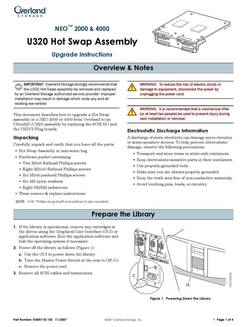
WARNING: It is recommended that a mechanical lifter (or at least two people) be
used to raise and align the unit to prevent injury during installation. Use care when
inserting or removing a unit into or out of a rack to prevent the accidental tipping of
the rack, causing damage or personal injury.
WARNUNG: Um Verletzungen zu vermeiden, empfehlen wir zur Rack-Installation oder
-Deinstallation die Nutzung einer mechanischen Hebehilfe (oder mindestens zwei
Personen). Seien Sie vorsichtig bei der Rack-Installation oder -Entnahme, um ein
versehentliches Kippen des Racks zu vermeiden und das Rack nicht zu beschädigen
bzw. sich selbst zu verletzen.
AVERTISSEMENT: Afin d’éviter des blessures pendant l’installation, il est
recommande d’utiliser un monte-charge (ou au moins deux personnes) pour élever ou
aligner l’appareil. Faites attention lorsque vous insérez ou retirez l’appareil d’un
support, pour empêcher le déversement accidentel de la crémaillère causant des
dommages et des blessures.
1. Starting at the bottom set of rails, extend the middle rails until they lock,
moving the sliding assembly to the front of the middle rails.
2. Using the mechanical lifter, position the module in front of the rack, aligned with
the extended rails.
3. Slide the unit onto the middle rails and into the rack until it stops.
4. Secure it to the rack with the captive screws on the front of the unit.
5. Repeat Steps 1–4 for the remaining modules in the correct order.
Aligning and Connecting Modules
Aligning the modules ensures that the robot can move freely between the modules. The
library will not operate unless the alignment mechanism is in the locked position.
1. From the front of the library, loosen the thumbscrews on each of the modules
two full turns.
2. From the back of the library, starting with the bottom pair of modules, align each
module with the module below. Repeat for each pair of modules.
a. Loosen the thumbscrew (1) on the module alignment mechanism.
b. Lower the alignment mechanism (2). If you encounter resistance, adjust the
position of the upper module so the pin in the alignment mechanism moves into
the hole in the lower module.
c. When the alignment mechanism is in the locked position, tighten the
thumbscrew (3).
3. Verify that the lowest module in the library has its alignment mechanism secured
in the unlocked position with the thumbscrew.
4. From the front of the library, use your fingers to tighten the thumbscrews on each
of the modules to secure the modules to the rack.
Step 4
WARNING: To reduce the risk of electric shock or damage to equipment, always
remove any power cords while working with the unit.
WARNUNG: Um das Risiko eines elektrischen Schlags oder Schäden am Gerät zu
vermeiden, ziehen Sie stets den Netzstecker, bevor Sie an der Einheit arbeiten.
AVERTISSEMENT: Pour réduire le risque de choc électrique ou endommagement de
l'équipement, retirez toujours les cordons électriques en travaillant avec l'appareil.
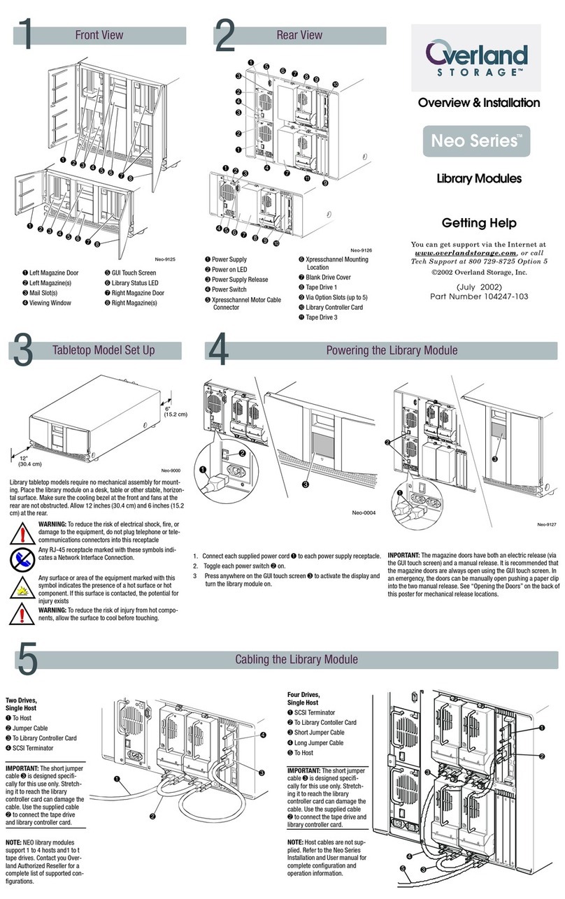
The expansion modules accept add-on components to enhance performance:
•The units come with one tape drive installed. Additional tape drives can be
installed in the empty bays. Always install the drives from the bottom up.
•Additional expansion modules can be added to the stack.
Once the expansion is secure in the rack, the additional items should then be installed
before hooking up the system. Follow the instructions enclosed with the add-on.
Step 5
Cable Attachment
1. Attach one end of the host interface cable to the expansion:
•For a Serial Attached SCSI (SAS) connected expansion, attach one end of the
SAS cable to Port A (left) SAS HBA on the SAS drive.
•For a Fibre Channel (FC) expansion, attach one end of the fibre cable to
Port A (top) connector on the FC drive, removing the cap if necessary.
2. Attach the other end of the host interface cable as follows:
•For a SAS expansion, connect the host interface cable to the host HBA,
using a direct SFF-8088 connection.
•For a Fibre Channel expansion, connect the fibre cable to the host or switch.
3. From the back of the library connect the lower module of each pair to its adjacent
module using the expansion interconnect cable.
4. Plug the power cables into the power connectors on each module and into power
outlets.
NOTE: The expansion has dual redundant power supplies. To increase redundancy, plug
each power cord into a different AC power circuit.
Step 6
The expansion can be operated using either the Operator Control Panel (OCP) on the
front of the library module or remotely using the Remote Management Unit (RMU)
web interface.
Power On the Expansion
1. Power on the expansion by pressing the base library power button just below
the OCP; the green light will illuminate.
2. Start the Initial Configuration Wizard from the OCP.
3. Verify the host connection.
Step 7
User Guides
For detailed information on configuring your NEOxl 60 or NEOxl 80, refer to the NEO
XL-Series Tape Library User Guide available online:
http://docs.overlandstorage.com/neo
Warranty and Technical Support
For warranty and general technical support information:
http://www.overlandstorage.com/company/contact-us/index.aspx
For information on contacting Overland Technical Support:
http://docs.overlandstorage.com/support
Expansion
Module
Base
Library
Expansion
Module
Expansion
Cables


