Overstayer IMPERIAL CHANNEL 877 Series Operator's manual

IMPERIAL CHANNEL 8776A
REFERENCE v1.1

INTRODUCTION
The 877 series modules are self powered, self contained channels that can be used on their
own (no chassis required) or as part of a larger framework for recording and mixing.
The 8776A features mic, line, and instrument inputs, as well as filters, 4 band eq, FET limiting,
and controls to shape and exploit the harmonic character of the circuitry throughout. Modules
can be mounted vertically in dual, quad, or a 10 space rack-mountable chassis (5RU high).
Audio connections are via XLR and TRS connectors with access to several points in the signal
path.
The Imperial Channel’s preamp and drive amps were inspired by late 60’s English solid state
consoles. Their primitive design makes them incredibly forgiving with a wide range of
nonlinearities before overt clipping (a wide sweet spot), and with that they are generous with
low order harmonics, and can be driven into full distortion. These stages are ‘cushioned’ in this
design allowing them to be used exploited in new ways.
The concept of the channel is to have a fluid interactive chain, where creative decisions can be
made by immediately by turning controls and switches. Multiple stages distribute the rounding
and harmonics, each with different characters. The HARMONICS stage at the end of the chain
has MAS circuitry, and can ‘control’ peaks, and smooth harsh frequencies, allowing the
equalizer for instance to be approached creatively and aggressively. As an example, the
proportional Q bells have a large amount of gain and can be driven almost to the point of
oscillation, which can sound raw on its own, but driven into the harmonics circuitry can be
‘absorbed into the signal and become a band of harmonic distortion.
FEATURES
●Microphone, line, and instrument inputs
●Transformer coupled input and output
●Multiple discrete gain stages
●High and low pass filters
●4 band equalizer with high and low shelving boosts, and 2 fully sweepable mid bands
●FET Limiting Amplifier with sidechain filter and 3 position attack and release controls
●MAS harmonics
●Independent preamp (dry) and channel (wet) output faders for parallel processing
●Polarity, pad and phantom power
●4 segment level and gain reduction metering
Copyright © 2018, Overstayer Recording Equipment, Inc.. All rights reserved. All features and specifications subject to change without notice

SAFETY AND INSTALLATION
Installation
1. Before attaching the DC plug of an adaptor to equipment, please unplug the adaptor
from the AC power and verify the unit is within the voltage and current rating on the
equipment.
2. Keep the linkage between the adaptor and its power cord tightly as well as connecting
the DC plug to equipment properly.
3. Protect the power cord from being trodden on or being squashed.
4. Use only an approved power cord, do not defeat the safety grounding pin which must
be connected to earth at all times (do not use a ground lift).
5. Keep good ventilation for the unit in use to prevent it from overheating. Do not install
near any heat source or device that produces heat.
6. An approved power cord should greater or equal to SVT, 3G×18AWG or H03VV-F,
3G×0.75mm2.
7. If the final equipment is not used for long period of time, disconnect the equipment
from power supply to avoid being damaged by voltage peaks or lightning strike.
Warning / Caution !!
1. Risk of electrical shock and energy hazard. All failure should be examined by a qualified
technician. Please do not remove the case of the adaptor by yourself!
2. Risk of fire or electrical shock. The openings should be protected from foreign objects
or dripping liquids.
3. Using wrong DC plug or forcing a DC plug into an electronic device may damage the
device or cause to malfunction.
4. Adaptors should be placed on a reliable surface. A drop or fall could cause damage.
5. Do not use or install in places with high moisture or near the water.
6. Do not use or install in places with high ambient temperature or near fire source.
7. Disconnect the unit from the AC power before cleaning. Do not use any liquid or
aerosol.
8. Please contact your local qualified recyclers when you want to dispose this product.
Copyright © 2018, Overstayer Recording Equipment, Inc.. All rights reserved. All features and specifications subject to change without notice

GETTING STARTED
To get a sense of the signal flow and gain structure, you can start
with the settings pictured, which uses the balanced LINE IN A
input, but the process is the same for MIC and INST.
PREAMP GAIN
To set the preamp gain, adjust DRIVE to 0, CHANNEL fader (upper)
to 10, and the meter switch to VU1. EQ, HPF, LPF, LIM, and HARM
should all be bypassed. Adjust the GAIN control for roughly unity,
which should fall between 1 and 3 leds on the meter (4 is at
clipping).
EQUALIZER
Adjust the CHANNEL fader down to ~7/8 to give some headroom
(especially for low boosts), and engage the EQ to the middle
position (EQ IN). The EQ is capable of large boosts, so you may
also need to adjust the GAIN to maintain headroom. You can
sweep the shelves, which are passive and broad to get a feel. The
bells are proportional Q and have a wide frequency and boost/cut
range. This allows them to be used ‘sensibly’ but also in their
extremes of gain approach self oscillation. The EQ IN switch up
position is a special mode that allows cleaner low boosts at higher
DRIVE settings.
HARMONICS
Engage HARM (middle position is stronger 3rd, upper 2nd) to see
how it interacts and can ‘control’ the eq boosts. Increase DRIVE,
compensating with the CHANNEL fader to get it’s feel, with and
without HARM engaged. The threshold of the HARM circuitry is
lower than the threshold of the DRIVE amplifier, so it can be
driven somewhat cleanly if desired. The HARM smooths, rounds
peaks, and generates low order harmonics, and is critical in that it
allows all the blocks ahead of it (Filters, EQ, Limiter) to be used
more broadly (somewhat of a safety net to get wild).
DRIVE
DRIVE is post shelves and pre bells, so you can shape tonally into
it and after it. Increase DRIVE, compensating with the CHANNEL
fader to get it’s feel, with and without HARM engaged. DRIVE is
post shelves and pre bells, so you can shape tonally into it and
after it. The threshold of the HARM circuitry is lower than the
threshold of the DRIVE amplifier, so it can be driven somewhat
cleanly if desired. DRIVE can go deep into distortion, and
experimenting with HARM settings has a dramatic effect on how
raw or smooth this can sound.
Copyright © 2018, Overstayer Recording Equipment, Inc.. All rights reserved. All features and specifications subject to change without notice

LIMITER
Set DRIVE back close to 0, and engage the LIM IN, then adjust the LIM IN control to set the
desired amount of limiting, and compensate with the LIM OUT control. Setting the LIM IN
switch to the top SC HPF position engages the limiter with a hpf on the sidechain. Set the
meter switch to LIM to show gain reduction on the meter. The limiter comes after the eq and
DRIVE, and before the HARM circuits, so when it is engaged, DRIVE effects how hard the limiter
is driven, and LIM OUT effects how hard HARM is driven.
PARALLEL MIXING
The PREAMP fader, which is essentially a dry signal (unless the GAIN is overdriven) allows the
parallel mixing with the fully processed CHANNEL fader and the dry MIX fader. The faders are
additive so they may require balancing to maintain headroom. The preamp fader has an
access point on the rear panel, and any other signal from the unit (EQ, or LIMITER for
example) can be patched here. An external signal (effects, pedal, etc.) can also be patched
here.
*The Imperial Channel is as much an instrument as a classic channel. It has several gain stages
that are collectively capable of massive amounts of gain. High and low frequency instability
and noise are possible especially at high gain settings, extreme limiting, and LMF shelf boosts,
so be aware to keep headphone and speaker levels in check at all times.
Copyright © 2018, Overstayer Recording Equipment, Inc.. All rights reserved. All features and specifications subject to change without notice

SIGNAL FLOW
Copyright © 2018, Overstayer Recording Equipment, Inc.. All rights reserved. All features and specifications subject to change without notice

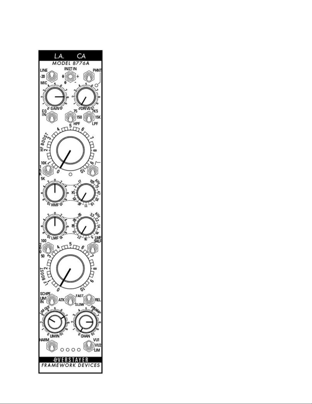
FRONT PANEL CONTROLS
INPUT SWITCH
LINE - Selects the balanced line input as the source (LINE IN A), in
this mode unity will be ~8 on the GAIN control.
-20 - Selects the microphone input as the source, padded 20 dB
MIC - Selects the microphone input as the source.
INSTRUMENT INPUT, POLARITY SWITCH
INST IN -Selects the high impedance unbalanced INST IN as the
source, over-riding the LINE, -20, MIC switch. If nothing is plugged
into the INST IN connector, the source is unbalanced LINE IN B,
which can accept higher level signals than the INST IN, and can be
better for synths, drum machines, etc. that have higher output
levels.
POLARITY +/- - Changes the polarity of the balanced LINE or MIC
signal.
PHNT - Engages phantom power to the microphone input.
GAIN - Controls the amount of preamp gain.
DRIVE - Controls the gain of the DRIVE amplifier (unity is 0), which is
post shelves (HF BOOST, LF BOOST), and pre bells (HMF, LMF).
FILTERS
HPF - High pass filter selectable between 75Hz, 150Hz, and bypass.
LPF - Low pass filter selectable between 7K5Hz, 15KHz, and bypass.
TRANSFORMER CURVE - Changes the response curve of the output
transformer, 50Hz rolloff with a resonant peak (loading dependent)
EQUALIZER
EQ IN - 3 positions, bypass, EQ in, EQ with curve.
HF BOOST - High frequency shelf boost with 3 selectable
frequencies, 5KHz, 10KHz, 15KHz.
LF BOOST - Low frequency shelf boost with 3 selectable frequencies,
50Hz, 100Hz, 200Hz.
HMF DB/KHZ - High mid frequency bell with >20dB of boost or cut.
LMF DB/KHZ - Low mid frequency band with >20dB of boost or cut.
LMF SHLF - Changes the low mid bell to a low shelf.
LIMITING AMPLIFIER - FET limiter with input (inside) and output
(outside) level controls. Features a selectable 200Hz sidechain high
pass filter and 3 position attack and release controls.
HARMONICS - MAS harmonics stage selectable between stronger
2nd harmonic, stronger 3rd harmonic, and bypass.
PARALLEL FADERS - Dual output faders, one for the full channel
path (wet), and one fed directly from the preamp (dry) for parallel
compositing within the channel.
Copyright © 2018, Overstayer Recording Equipment, Inc.. All rights reserved. All features and specifications subject to change without notice

METER SOURCE - Selects between the preamp (VU1), harmonics (VU2), and gain reduction
(LIM).
REAR PANEL CONNECTIONS
The 8776A has extensive audio interconnects on the rear panel. Each
circuit block has its own input and half normalled output, allowing
multiple signals to be recorded simultaneously, as well as allowing
the signal flow to be re-configured with patch cables.
MIC IN
Balanced transformer coupled microphone input.
LINE IN A
Balanced transformer coupled line input.
LINE IN B
Unbalanced line input.
INST IN
Unbalanced high impedance instrument input.
PREAMP OUT
Direct output post HPF.
EQ IN
Direct input pre Equalizer, normalled to the PREAMP OUT.
EQ OUT
Direct output post Equalizer.
COMP IN
Direct input pre Limiter, normalled to EQ OUT.
COMP OUT
Direct output post Limiter.
HARM IN
Input pre Harmonics, normalled to COMP OUT.
HARM OUT
Direct output post Harmonics.
LINE OUT
Balanced transformer coupled line output.
AUX
The AUX jack provides access to the PREAMP (dry) fader, allowing an
alternate signal to be mixed in, either from another point in the unit,
or externally (pedals, etc.).
Copyright © 2018, Overstayer Recording Equipment, Inc.. All rights reserved. All features and specifications subject to change without notice

8776A PATCHING EXAMPLES
EXAMPLE 1 (left) - Re-arranges the signal path to put the LIMITER before the EQ.
EXAMPLE 2 (middle) - Makes the PREAMP fader (dry) post EQ. Alternately the AUX can be fed
from the COMP OUT to blend the Limiter with the Harmonics.
EXAMPLE 3 (right) - Allows an external device to be blended in parallel using the PREAMP
fader. The external device can be fed from any output in the signal path.
Copyright © 2018, Overstayer Recording Equipment, Inc.. All rights reserved. All features and specifications subject to change without notice
This manual suits for next models
1
Table of contents
Other Overstayer Recording Equipment manuals
Popular Recording Equipment manuals by other brands

Solid State Logic
Solid State Logic VHD+ user guide

Fisher-Price
Fisher-Price H4656 user manual

Universal Audio
Universal Audio Apollo x4 Hardware manual

Intesis
Intesis INKNXACA I000 Series quick start guide

Friendly Songs
Friendly Songs Sound Module user guide

Emerson
Emerson Bettis OM9-SCE300 Installation, operation and maintenance manual