Ovislink Air Live WLA-5000AP User manual

User’s Guide
WLA-5000AP
Client Mode

Copyright Statement
No part of this publication may be reproduced, stored in a retrieval system, or
transmitted in any form or by any means, whether electronic, mechanical,
photocopying, recording or otherwise without the prior writing of the publisher.
Windows™95/98 and Windows™2000 are trademarks of Microsoft®Corp.
Pentium is trademark of Intel.
All copyright reserved.

1
Table of Contents
1. Introducing the WLA-5000AP Ethernet Adapter ..................................................3
1.1 Overview of the Device .............................................................................3
1.2 Features......................................................................................................3
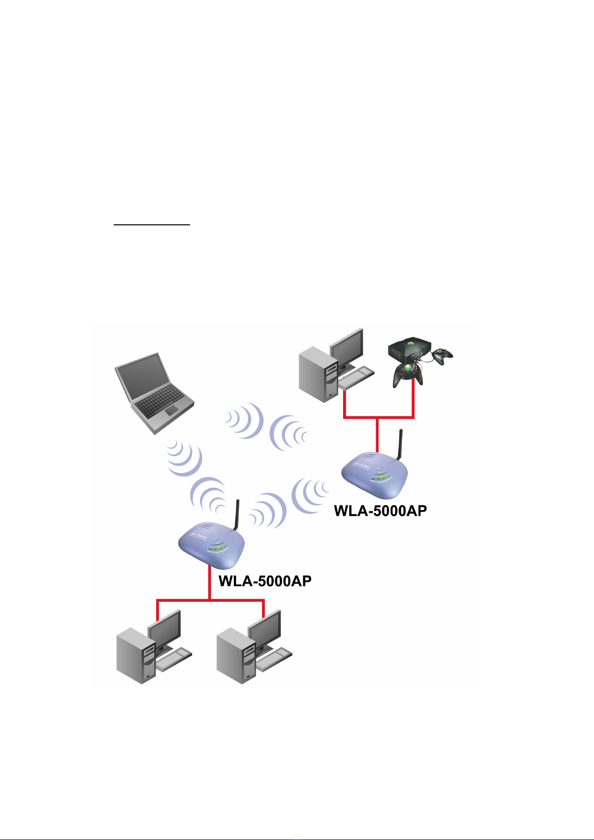
1.3 Network Configuration Examples .............................................................4
1.4 Setting Up the device.................................................................................6
2. Installing the WLA-5000AP Ethernet Adapter......................................................7
2.1 What’s in the Box?.....................................................................................7
2.2 Connecting the Cables ...............................................................................7
2.3 Configuration Concept...............................................................................8
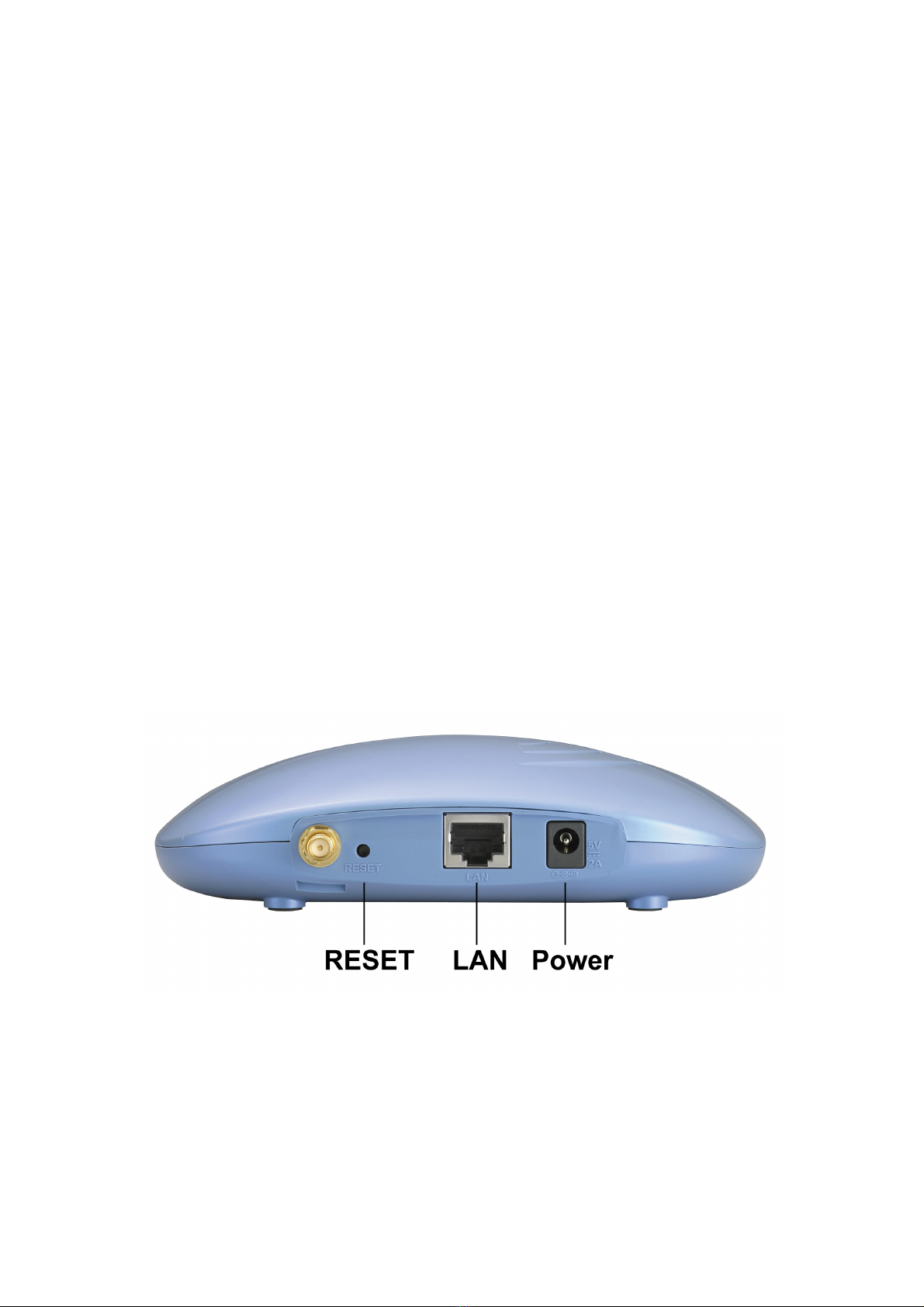
2.4 Front Panel.................................................................................................9
2.5 Connecting More Devices Through A Hub To The WLA-5000AP
Ethernet Adapter ..................................................................................................10
3. Configuration .......................................................................................................11
3.1 Logging On ....................................................................................................12
3.2 Setup Wizard..................................................................................................12
3.2.1 Time Settings ......................................................................................12
3.2.2 Device IP Settings...............................................................................13
3.2.3 Wireless Settings.................................................................................14
3.2.4 Finish Setup Wizard and Save Your Settings......................................16
3.3 Advanced Settings..........................................................................................16
3.3.1 Password Settings ...............................................................................17
3.3.2 System Management...........................................................................17
3.3.3 Oerational Mode Setting.....................................................................19
3.3.4 Wireless Settings.................................................................................20
4. Managing the WLA-5000AP Ethernet Adapter...................................................21
4.1 How to View the Device Status .....................................................................21
4.2 How to View the System Log ........................................................................21
4.3 Bridge Table.............................................................................................22
4.4 Site Survey...............................................................................................23
4.5 Upgrading Firmware................................................................................23
4.6 How to Reset the Configuration to the Factory Default ..........................24
4.7 How to Reboot Your WLA-5000AP Ethernet Adapter............................25
4.8 What If You Forgot the Password? ..........................................................26
5. Product Specification...........................................................................................27

2
Regulatory Information
Federal Communication Commission Interference Statement
This equipment has been tested and found to comply with the limits for a Class
B digital device, pursuant to Part 15 of the FCC Rules. These limits are
designed to provide reasonable protection against harmful interference in a
residential installation. This equipment generates, uses and can radiate radio
frequency energy and, if not installed and used in accordance with the
instructions, may cause harmful interference to radio communications.
However, there is no guarantee that interference will not occur in a particular
installation. If this equipment does cause harmful interference to radio or
television reception, which can be determined by turning the equipment off and
on, the user is encouraged to try to correct the interference by one of the
following measures:
- Reorient or relocate the receiving antenna.
- Increase the separation between the equipment and receiver.
- Connect the equipment into an outlet on a circuit different from that to which
the receiver is connected.
- Consult the dealer or an experienced radio/TV technician for help.
FCC Caution: To assure continued compliance, (example - use only shielded
interface cables when connecting to computer or peripheral devices) any
changes or modifications not expressly approved by the party responsible for
compliance could void the user’s authority to operate this equipment.
This device complies with Part 15 of the FCC Rules. Operation is subject to the
following two conditions: (1) This device may not cause harmful interference,
and (2) this device must accept any interference received, including
interference that may cause undesired operation.
IMPORTANT NOTE:
FCC Radiation Exposure Statement:
This equipment complies with FCC radiation exposure limits set forth for an
uncontrolled environment. This equipment should be installed and operated
with minimum distance 20cm between the radiator & your body.
This transmitter must not be co-located or operating in conjunction with any
other antenna or transmitter.

3
1. Introducing the WLA-5000AP Ethernet
Adapter
1.1 Overview of the Device
The WLA-5000AP Ethernet Adapter is a wireless client based on IEEE
WLA-5000AP based 5/2.4-GHz radio technology. It contains an WLA-5000AP
and a full-duplex 10/100 LAN interfaces. The WLA-5000AP Ethernet Adapter
can function as a bridge to let data pass through between the Ethernet and the
wireless interfaces at a data rate up to 54 Mbps. It acts like a wireless client
and associates with a wireless Access Point to create the wireless connection.
The WLA-5000AP Ethernet Adapter can also function in the Ad Hoc (IBSS)
mode, which is used to construct a wireless network without a centralized
wireless Access Point. In the Ad Hoc mode, an WLA-5000AP Ethernet Adapter
can connect with other Ethernet Adapters and/or wireless Cardbus/PCMCIA
adapters to make a wireless network that connects multiple wired LAN
segments.
Since the 802.11g shares the same 2.4GHz radio band as the 802.11b
technology, it can inter-operate with existing 11Mbps 802.11b devices.
Therefore you can protect your existing investment in 802.11b Access Point
and/or client cards, and migrate to the high-speed 802.11g standard as your
needs grow.
To address growing security concerns in a wireless LAN environment, different
levels of security can be enabled in the WLA-5000AP Ethernet Adapter,
including:
¾To enable WEP (Wired Equivalent Privacy) 64, 128, or 156-bit encryption
to protect the privacy of your data.
1.2 Features
Compliant with draft 802.11a, 802.11b and 802.11g standards with
roaming capability.
Support of the standard client (station) mode for connection to a wireless
access point.

4
Support of wireless connection for multiple PC’s connected to the device
through wired LAN. TCP/IP traffic can flow between these PC’s and the
remote PC’s through the wireless connection.
Support of the Ad Hoc mode for several wireless clients/stations to create
a wireless network without a centralized Access Point.
Security measures: WEP encryption: 64 bits, 128 bits and 152 bits.
Extensive monitoring capability such as event logging, traffic/error
statistics monitoring. Support of remote logging.
Easy configuration and monitoring through the use of a Web-browser
based GUI. (We recommend users to use -- Windows-IE6.0; Linux-Mozilla
(1.01or above) and MAC-Safari v125.1.)
Site survey table.
Setup Wizard for easy configuration/installation
Firmware upgradeable.
Automatically connect to unsecured AP(s).
1.3 Network Configuration Examples
Infrastructure Mode
A group of wireless stations communicating with each other through a
centralized Access Point is called a Basic Service Set (BSS) and is identified
by a unique SSID.

5
When an WLA-5000AP Ethernet Adapter is used, it can be configured to
operate as a wireless station (infrastructure mode).
When acting in this mode, the WLA-5000AP Ethernet Adapter connects to a
wireless Access Point to link itself into a wireless network. It communicates
with other wireless stations through the AP. An WLA-5000AP Ethernet Adapter
provides bridging functions between the wireless network and the wired LAN
network.
Ad Hoc Mode
A group of wireless stations can form a wireless network without a centralized
Access Point involved. This is called an Independent Basic Service Set (IBSS
or Ad Hoc).
In this mode, an WLA-5000AP Ethernet Adapter connects to all other wireless
stations directly to communicate with each other.

6
1.4 Setting Up the device
A PC through either the wired or wireless network can manage the
WLA-5000AP Ethernet Adapter remotely. To do this, the WLA-5000AP
Ethernet Adapter must first be assigned an IP address.
This IP address can be modified to either a different address in this same
subnet or to an address in a different subnet, depending on the existing
netwrok settings (if there is any) or user’s preference.

7
2. Installing the WLA-5000AP Ethernet Adapter
This section describes the installation procedure for the WLA-5000AP Ethernet
Adapter. It starts with a summary of the content of the package you have
purchased, followed by steps of how to power up and connect the
WLA-5000AP Ethernet Adapter. Finally, this section explains how to
configure a Windows PC to communicate with the WLA-5000AP Ethernet
Adapter.
2.1 What’s in the Box?
The WLA-5000AP Ethernet Adapter package contains the following items:
One WLA-5000AP Ethernet Adapter
One 5V AC power adapter with a barrel connector
CD of the WLA-5000AP Ethernet Adapter User’ Guide
2.2 Connecting the Cables
The Back Panel of the WLA-5000AP Ethernet Adapter appears as follows:
Follow these steps to install your WLA-5000AP Ethernet Adapter:
1. Connect a LAN hub to the LAN port on the WLA-5000AP Ethernet Adapter
using the supplied LAN cable.
2. Connect the power adapter to an electrical outlet and the WLA-5000AP
Ethernet Adapter.

8
2.3 Configuration Concept
During the system installation time, you need to build an isolated environment
with the WLA-5000AP Ethernet Adapter and a PC, and then perform the
following steps:
1. Manually change the IP address of the PC to 192.168.1.3.
2. Connect the PC to the WLA-5000AP Ethernet Adapter and change its
configuration to a static IP address based on your network environment. For
example, if there is a the DHCP server that assigns IP addresses from the
range 192.168.23.10 - 192.168.23.254 to DHCP client devices, it can
reserve 192.168.23.10 for the WLA-5000AP Ethernet Adapter and then the
address pool with the DHCP server becomes 192.168.23.11 –
192.168.23.254.
3. If there is no DHCP server on your network environment, you just have to
make sure that there is no device in the environment has the same IP
address as another machine.
4. Please note that after you change the IP address of the Ethernet Adapter,
the PC client may not be able to reach the Ethernet Adapter. This is because
they may no longer belong to the same IP network address space.
¾Change the setting of the PC back to “obtain IP addresses Automatically”.
5. Now you can put the WLA-5000AP Ethernet Adapter and the PC to your
network where the DHCP server is connected, if there is any.

9
2.4 Front Panel
The LEDs on the front of the WLA-5000AP Ethernet Adapter reflect the
operational status of the unit. The status of the LAN, the wireless, and power
can be monitored from this display.
WLA-5000AP Ethernet Adapter LED Description
Label Wireless LAN POWER
SOLID Link is active Link is active Power
OFF No Wireless connection No LAN connection No Power
FLASH XMT/RCV Data XMT/RCV Data N/A

10
2.5 Connecting More Devices Through A Hub To The
WLA-5000AP Ethernet Adapter
The WLA-5000AP Ethernet Adapter provides an RJ45 LAN interface that you can
use to connect to a PC or an external hub.

11
3. Configuration
This section describes the basic configuration procedure for the WLA-5000AP
Ethernet Adapter. It describes how to set up the WLA-5000AP Ethernet
Adapter for wireless connections, and the configuration of the local LAN
environment.
The WLA-5000AP Ethernet Adapter is designed so that all basic configuration
may be effected through the a standard Web browser such as Microsoft
Internet Explorer.
From a PC that has been configured as described in Chapter 2, enter the IP
address of the WLA-5000AP Ethernet Adapter as the URL in your browser, e.g.
http://192.168.1.2
Note: The IP address of your PC must be in the same IP subnet as the
WLA-5000AP Ethernet Adapter.
The Home Page of the WLA-5000AP Ethernet Adapter screen will appear, with
its main menu displayed on the right hand side of the window. The main menu
includes the following choices: Setup Wizard, Device Status, Advanced
Settings, System Tools, and Help; these can be used to navigate to other
menus.

12
3.1 Logging On
If you attempt to access a configuration item from the browser menu, an
administrator login screen will appear, prompting you for the password in order
to log on.
If you are logging on for the first time, you should use the factory default setting
“password”. The password is always displayed as a string of dots. Click the
LOG ON button to start the configuration session.
3.2 Setup Wizard
The Setup Wizard will guide you through a series of configuration screens to
set up the basic functionality of the device. After you finish these screens,
press the “finish” button on the last screen to make all your modifications
effective.
3.2.1 Time Settings

13
After logging in, the Time Settings page appears. The device time is
automatically set to the local time of the management PC at the first time a
connection is made. To modify the device’s time, modify the appropriate fields,
then click “NEXT”.
3.2.2 Device IP Settings
The Device IP setting screen allows you to configure the IP address and
subnet of the device.
IP Address and IP Subnet Mask: These values default to 192.168.1.2 and
255.255.255.0, respectively. It is important to note that there are similar
addresses falling in the standard private IP address range and it is an essential
security feature of the device. Because of this private IP address, the device
can no longer be accessed (seen) from the Internet.
Gateway IP Address: Enter the IP address of your default gateway
DNS Server: The Domain Name System (DNS) is a server on the Internet that
translates logical names such as “www.yahoo.com” to IP addresses like
66.218.71.80. In order to do this, a query is made by the requesting device to a
DNS server to provide the necessary information. If your system administrator
requires you to manually enter the DNS Server addresses, you should enter
them here.
Click Next to go to the next screen.

14
3.2.3 Wireless Settings
Network Name (SSID): The SSID is the network name used to identify a
wireless network. The SSID must be the same for all devices in the wireless
network (i.e. in the same BSS or IBSS). Several access points on a network
can have the same SSID. The SSID length is up to 32 characters. Once you
specify a SSID here, the Ethernet Adapter will try to associate with an AP with
the same SSID that you specified. If there is no AP having the specified SSID,
the Ethernet Adapter will stay unassociated even there is another AP available
with a different SSID. You can leave this item unspecified, then the Ethernet
Adapter will try to associate with an AP with best signal strength.
Regulatory Domain: Please make sure that your regulatory domain matches
your region. The default value is FCC. For most regions, FCC may be the
better choice.
Security Policy: You can select different security policy to provide association
authentication and/or data encryption.

15
WEP
WEP allows you to use data encryption to secure your data from being
eavesdropped by malicious people. It allows 3 types of key: 64 (WEP64), 128
(WEP128), and 152 (WEP152) bits. You can configure up to 4 keys using
either ASCII or Hexadecimal format
Key Settings: The length of a WEP64 key must be equal to 5 bytes, a
WEP128 key is 13 bytes, and a WEP152 key is 16 bytes. For WEP64 and
WEP128, you can just enter a pass-phrase and click the GENERATE button to
generate the four keys. So you can use a mnemonic string as the pass-phrase
instead of memorizing the four keys.

16
Key Index: You have to specify which of the four keys will be active.
Once you enable the WEP function, please make sure that both the
WLA-5000AP ACCESS POINT and the wireless client stations use the same
key.
Note: Some wireless client cards only allow Hexadecimal digits for WEP keys.
Please note that when configuring WEP keys, a WEP128 ASCII key looks like
“This is a key”(13 characters), while a WEP128 Hex key looks like
“54-68-69-73-20-69-73-20-61-20-6b-65-79”(13 bytes).
3.2.4 Finish Setup Wizard and Save Your Settings
After stepping through the Wizard’s pages, you can press the FINISH button
for your modification to take effect. This also makes your new settings saved
into the permanent memory on your system.
Note: If you change the device’s IP address, as soon as you click on FINISH
you will no longer be able to communicate with your WLA-5000AP Ethernet
Adapter. You need to change your IP address and then re-boot your computer
in order to resume the communication.
3.3 Advanced Settings
The advanced settings tab on the top row of the window allows you to perform
modifications that normally you may not need to do for general operations
except changing your password from the default factory setting (this is highly
recommended for security purposes).

17
3.3.1 Password Settings
The default factory password is “airlive”. To change the password, press the
Password Settings button to enter the Password Settings screen and then
enter the current password followed by the new password twice. The entered
characters will appear as dots.
3.3.2 System Management
Clicking the System Management button to configure system related
parameters to for the WLA-5000AP Ethernet Adapter.

18
Management Utility Port Definition: The standard port settings for the HTTP
Web server and the Telnet utility may be replaced by entering new port
numbers in these fields.
Management Session Time-out: This setting specifies the duration of idle
time (inactivity) before a web browser or telnet management session times out.
The default time-out value is 10 minutes.
Syslog: Syslog is an IETF (Internet Engineering Task Force - the Internet
standards body)-conformant standard for logging system events (RFC-3164).
When the WLA-5000AP Ethernet Adapter encounters an error or warning
condition (e.g., a log-in attempt with an invalid password), it will create a log in
the system log table. To be able to remotely view such system log events, you
need to check the Enable Syslog box and configure the IP address of a
Syslog daemon. When doing so, the WLA-5000AP Ethernet Adapter will send
logged events over network to the daemon for future reviewing.
Syslog server IP address: The IP address of the PC where the Syslog
daemon is running.
Table of contents
Other Ovislink Adapter manuals

Ovislink
Ovislink OVT-12 Operator's manual

Ovislink
Ovislink EVO-W311AR User manual

Ovislink
Ovislink AirLive WN-380USB User manual

Ovislink
Ovislink PL-DUO210/85 User manual

Ovislink
Ovislink EVO-W301USB User manual

Ovislink
Ovislink AirLive HP-3000E User manual

Ovislink
Ovislink HP-1000E v2 User manual

Ovislink
Ovislink Air Live GE-2032R User manual

Ovislink
Ovislink WIRELESS-G PCI ADAPTER User manual

Ovislink
Ovislink AirLive EtherWe-1000U User manual