OWC Multi-Mount for Mac Pro User manual
Multi-Mount for Mac Pro
3.5" to 5.25" Drive Bay Converter Bracket
2.5" to 3.5" Adapter Bracket
Assembly & Installation Manual

1 INTRODUCTION
1.1 System Requirements
1.1.1 Computer Requirements
1.1.2 Hard Drive Requirements
1.1.3 Tool Requirements
1.2 Package Contents
OWC Multi-Mount Introduction
2 MAC PRO 667MHZ DISASSEMBLY
2.1 Mac Pro 667MHz Disassembly
3 MAC PRO 800MHZ DISASSEMBLY
3.1 Mac Pro 800MHz Disassembly
4 CABLE INSTALLATION
4.1 Cable Installation
5 OWC MULTI-MOUNT ASSEMBLY
5.1 Installing either 1 or 2 3.5" Hard Disk Drives
5.2 Installing a 2.5" Hard Disk Drive into the OWC Multi-Mount
5.3 Installing 1 or 2 2.5" Hard Disk Drives
5.4 Installing 1 2.5" Hard Disk Drive and 1 3.5" Hard Disk Drive
6 OWC MULTI-MOUNT INSTALLATION
6.1 Installing the OWC Multi-Mount into a Mac Pro
7 TROUBLESHOOTING & TIPS
7.1 Troubleshooting
7.2 Usage Tips
8 APPENDIX
8.1 FAQ
8.2 About Data Protection
9 CUSTOMER SERVICE
9.1 BEFORE CONTACTING CUSTOMER SERVICE
9.2 CONTACT INFORMATION
IMPORTANT NOTE:
The OWC Multi-Mount drive mounting system brackets are sold
both individually, and also as sets. This manual encompasses both
types of brackets. Please be aware that the item you purchased may
not include all of the items listed here. Please see your invoice for
specic items ordered.
Got tools? If you don’t have the tools necessary to complete this in-
stallation, Newer Technology has a fantastic toolkit which includes ev-
erything you need to perform this and most other common computer
hardware installations.
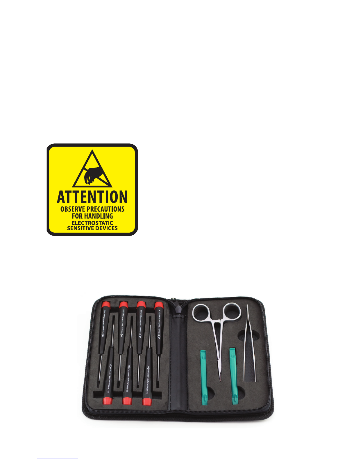
Your computer is a static-sensitive device. It is
susceptible to invisible damage if not protected
during installation.
We recommend proper grounding through the use
of a grounding strap. Be sure to work in a clean and
static-free area, and avoid wearing clothing that
retains static charges.
For more information, please visit
http://www.macsales.com/static
It’s available at:
http://www.macsales.com/tools
Thank you for purchasing the OWC Multi-Mount system. We’re con-
dent that it will provide years of high-performance service to you.
This guide will get you up and running quickly, demonstrating how
to install your own hard drives into the OWC Multi-Mount bracket
system and into 2 common types of computers.
Should you require additional support after reading this manual
along with the helpful tips and FAQs, please see the inside back
page for OWC customer support options.
OWC Multi-Mount Introduction

OWC Multi-Mount Chapter 1 - Introduction
1 INTRODUCTION
1.1 System Requirements
1.1.1 Computer Requirements
Any 2006 - 2008 Mac Pro system
1.1.2 Hard Drive Requirements
The OWC Multi-Mount is designed to work with any 3.5" or 2.5"
mechanical hard disk drive, or SSD drive.
1.1.3 Tool Requirements
• Phillips #1 or #2 Screwdriver
• Needlenose Pliers or Hemostats
1.2 Package Contents
➀
➁
➂
➄
➅
➆
➇
Item _________________________________________
➀ 4 Pin Power to SATA Power Y Cable or single SATA Power Cable*
➁ SATA Straight - Straight Cable*
➂ SATA "L" - Straight Cable*
➃ OWC Multi-Mount 3.5" Drive Bracket (2 pieces)
➄ OWC 2.5"-3.5" Adapter Bracket (1 pieces, 1 required per drive)*
➅ Screws for 3.5" Bracket - Coarse Thread (16 pieces)*
➆ Screws for 2.5" Bracket - Fine Thread (12 pieces)*
➇ Installation Manual
*NOTE: Depending on model purchased, contents may
dier. Sold as individual units, and as complete sets.
Please check your invoice for proper contents.
➃

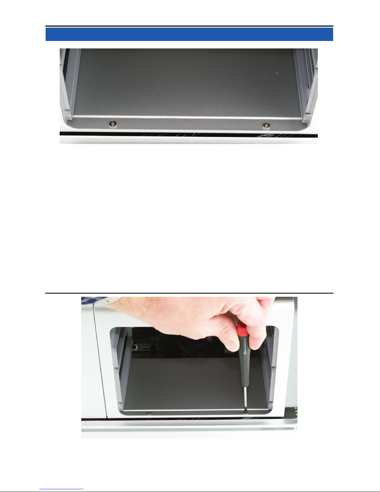
Begin by removing the side door on your Mac Pro.
On the lower right, nd the memory bay.
OWC Multi-Mount Chapter 2 - Mac Pro 667MHz Disassembly
2 MAC PRO 667MHZ DISASSEMBLY
2.1 Mac Pro 667MHz Disassembly

Remove the 2 memory riser cards, exposing the 2 Phillips screws shown
here.
Remove the 2 Phillips screws. They are long and extend through the
logic board and into the back of the computer.
OWC Multi-Mount Chapter 2 - Mac Pro 667MHz Disassembly
2 MAC PRO 667MHZ DISASSEMBLY
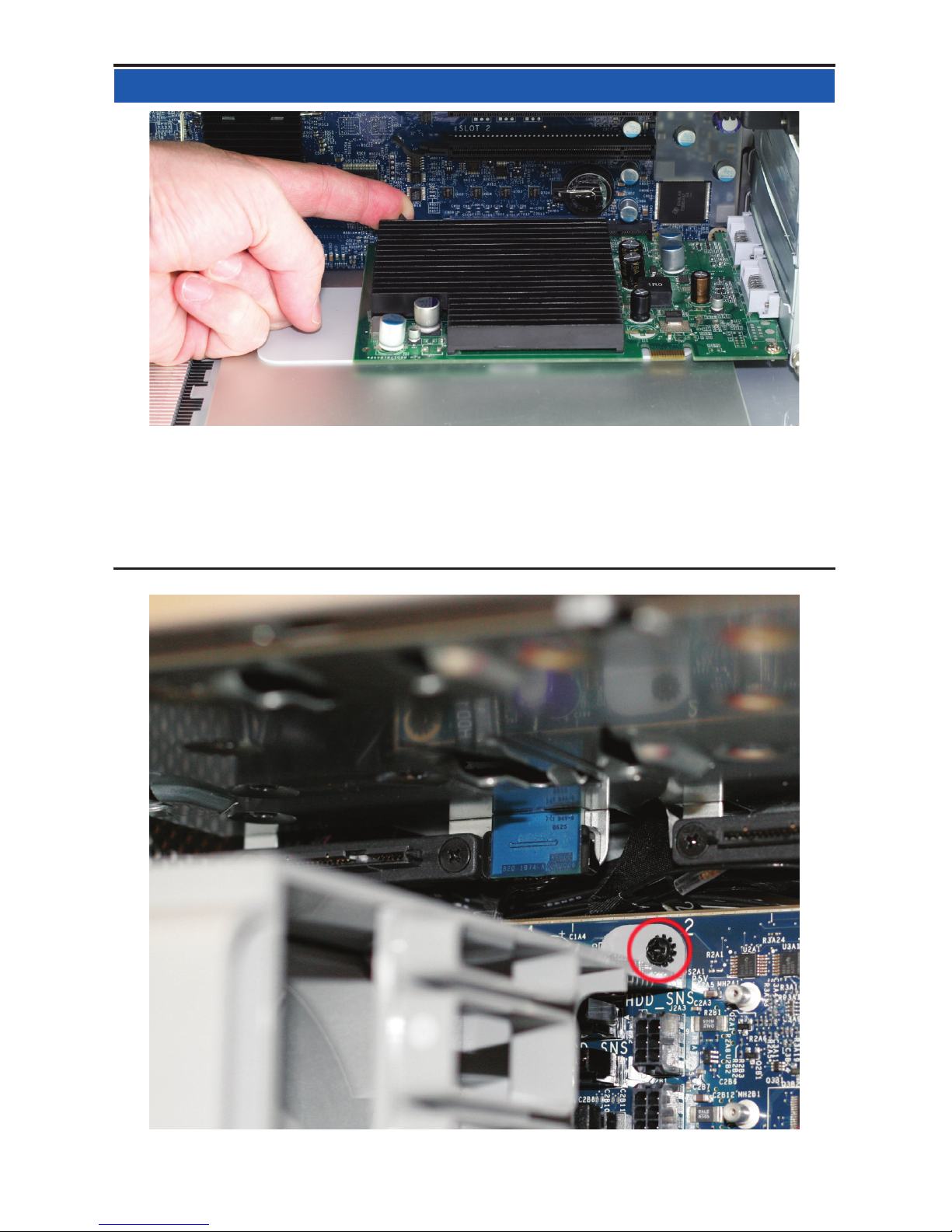
At the bottom of the memory bay, there are 2 more Phillips screws. They
are a smaller head than the ones inside the memory bay that you just
removed. Use a Phillips #0 screwdriver to remove the screws.
There is one problem. On many machines, the screws were improperly
installed. Instead of using loctite on the screw stando, Apple used loc-
tite on the screws themselves, into the standos - without loctite on the
standos that thread into the Mac Pro’s chassis.
This means, when you try and remove the screws, the standos them-
selves that the screws are screwed into turn. You may need to use a
very thin pair of needlenose pliers, hemostats, or even a thin at blade
screwdriver to hold the hex-shaped stando tight, while you loosen the
Phillips screws.
A photo of this task being made look easy, at least if your screws are not
improperly installed as described above. Try and not strip the Phillips
screw heads.
OWC Multi-Mount Chapter 2 - Mac Pro 667MHz Disassembly
2 MAC PRO 667MHZ DISASSEMBLY

Make sure that the locking latch on the back right side of the Mac Pro.
Then, remove all 4 of the drive bays and set them aside.
Look inside the PCI Express bay at the top right of the Mac Pro. You’ll
need to remove items from this location next.
OWC Multi-Mount Chapter 2 - Mac Pro 667MHz Disassembly
2 MAC PRO 667MHZ DISASSEMBLY

Using a Phillips P0 screwdriver, loosen the PCI Express cover retaining
plate and remove it. There is a tab at the top that the metal plate latches
into, you’ll need to unscrew the 2 screws and slide the plate down out of
the tab.
Once the metal retaining plate is removed, remove the top PCI Express
dead plate cover from the top slot as shown. Set the dead plate cover
aside, you’ll be using it in a future step.
OWC Multi-Mount Chapter 2 - Mac Pro 667MHz Disassembly
2 MAC PRO 667MHZ DISASSEMBLY
Remove your PCI Express video card. At the rear of the PCI Express slot,
there is a small plastic tab that you need to lift up to unlock the PCI
Express card. While doing this, pull gently on the card itself toward you
and it will come free. Set the video card aside.
Immediately to the left of the PCI slots, at the top of the logic board, you
will see this Phillips screw. Using a Phillips P0 screwdriver, remove it.
OWC Multi-Mount Chapter 2 - Mac Pro 667MHz Disassembly
2 MAC PRO 667MHZ DISASSEMBLY
Table of contents
Other OWC TV Mount manuals


