Oxgard Praktika T-05 Instruction sheet

Installation
guidelines
www.oxgard.com
Tel.+7(812) 366-15-94
Praktika T-05(K) speedgate


Installation guidelines 3
Content
1. Basic specifications.................................................................................. 5
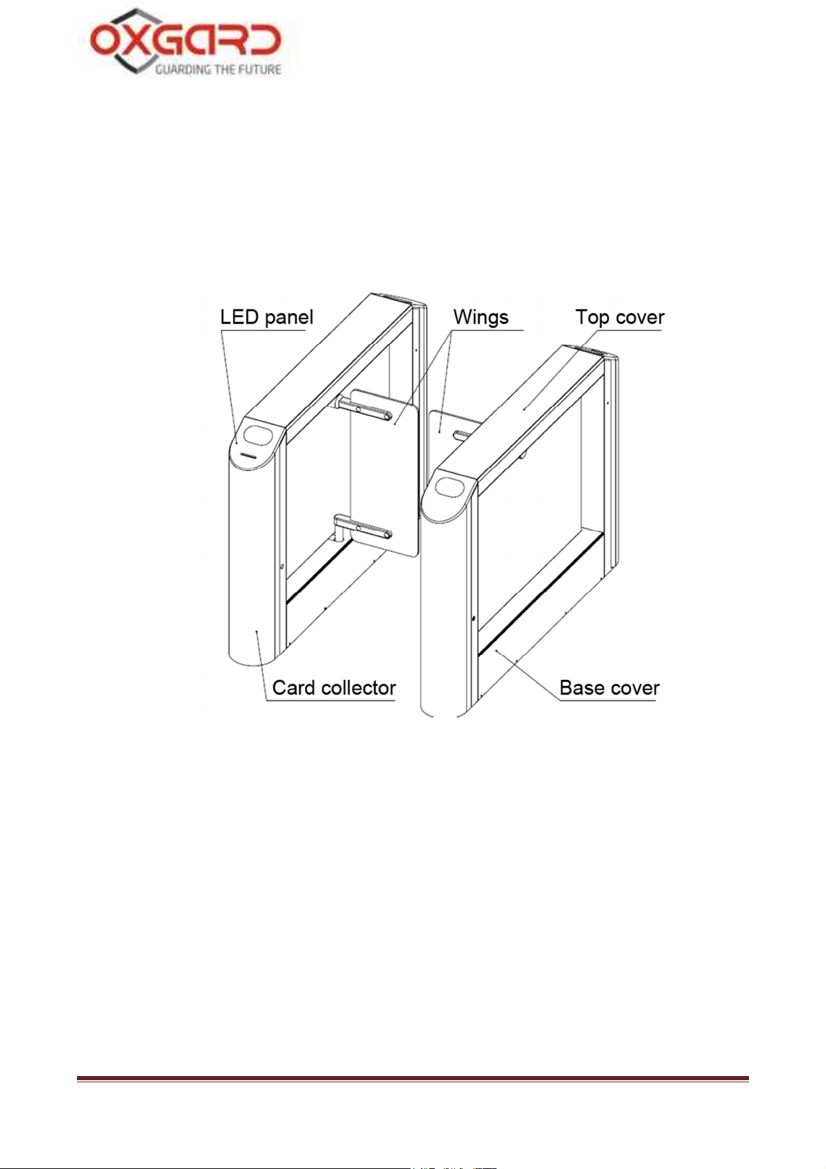
2. Product design.......................................................................................... 6
3. Safety requirements.................................................................................. 9
4. Installation of speedgate......................................................................... 10
4.1. Required equipment........................................................................ 10
4.2. Installation of speedgate.................................................................. 11
5. Connecting speedgate............................................................................. 14
5.1. Connecting power supply................................................................ 15
5.2. Connecting remote control panel.................................................... 16
5.3. Connecting side units...................................................................... 17
5.4. Connecting access control system (optional).................................. 19
6.1. Card collector description............................................................... 24
6.2. Connecting power supply................................................................ 26
6.3. Connecting operating device........................................................... 27
6.4. Connecting ACS controller............................................................. 28
6.5. Installation of proximity card reader............................................... 30
Appendix 1. Summary of the data bus CAN2.0 ........................................ 33
Appendix 2. Block diagram of ACS with using the card reader............... 35
Appendix 3. Location of mounting holes in relation to the overall
dimensions of the
speedgate…………………………………………………….....38
Appendix 4. Block diagram of minimal connections for synchronized
operation of wings with the use of one RC panel...................................... 40

Praktika T-05(K) speedgate 4
List of abbreviations
PS – power supply
FA – fire alarm
RC – remote control
ACS – access control system
OD – operating device (turnstile)
NC – normally connected
NO – normally opened
Speedgate firmware version FW v2.0-2.2
Card collector firmware version FW v1.52

Installation guidelines 5
1. Basic specifications
Table 1 Basic specifications
Description Speedgate RC panel
Dimension of side unit with open wings
(mm) (HхWхL) 1050х1500х200
107х107х25
Dimension of side unit depending on
passage lane (mm)
660
900
1050х1500х500
1050х1500х620
107х107х25
Weight of side unit
depending on passage
lane, kg 660
900
110,0
113,0
0,5
Temperature range,
0
C
operation
- transportation and storage
+1...+40
+1...+40
+1...+40
+1...+40
Atmosphere relative humidity, no more
than % 80 80
Throughput, persons per minute
30
Card collector capacity (pcs.)
**
More than 500
Max. number of connected RC panels, pcs 2
Lifetime, years 8 8

Praktika T-05(K) speedgate 6
Table 2 Electrical specifications
Description Speedgate Card collector** RC panel
Supply voltage, V:
- nominal
- working
12,0
10,8...15,0
12,0
8…18,0
12,0
7,5...15,0
Average current
in standby
mode * A 0,4 0,2
Average
current operational
mode * A 3,0
Maximal current of
1 side
unit*/***, A 5,0
Maximal current
of card
collector*, A 1,5
*- values mentioned at a nominal supply voltage
**-optional
***-
to form a passage area required 2 side units, i.e. 2 power supply 12V 5A
The producer reserves the right to change the packaging, specifications and appearance without
notice
2. Product design
Speedgate housing
Speedgate housing is made of brushed stainless steel, wings are made
of tempered glass. Additionally the card collector can be integrated in the
design of the speedgate. Base covers for access to PU, RC and ACS cables
holes (Fig. 1) are provided at the bottom of side units.

Installation guidelines 7
Speedgate may have only a single passage, however an unlimited
number of passages can be arranged with the use of side units and middle
units, depending on customer requirements.
Fig. 1 General view of speedgate
LED panel
Display panel of the speedgate is made of artificial stone with an
insertion made of acrylic glass. Speedgate operating modes are displayed
on the panel in the form of mnemonic signs depicting authorization and
non-authorization (Fig. 2).

Praktika T-05(K) speedgate 8
Fig. 2 General view of LED panel display
Remote Control Panel
The housing of RC panel is made of polished stainless steel. On the
front side there are control buttons and LED indicators of RC operational
modes (Fig. 3). The standard supplied cable is 5 m long.
Fig. 3 General view of remote control panel

Installation guidelines 9
3. Safety requirements
CAUTION! Failure to comply with the safety requirements specified in
this section may result in damage to human life and health, total or partial
loss of workability of products and (or) auxiliary equipment.
CAUTION! The producer disclaims any liability for damage to human life
and health, total or partial loss of workability of products and (or) auxiliary
equipment for non-compliance of the safety requirements specified in this
section, as well as terminates the product warranty.
IT IS NOT ALLOWED TO:
•Set the power supply unit inside the speedgate housing as this could
lead to electric shock to persons;
•Set the speedgate other than in dry and heated places;
•Impede or accelerate the speedgate wings;
•Apply chemically aggressive cleaning detergents as pastes and
liquids.

Praktika T-05(K) speedgate 10
4. Installation of speedgate
CAUTION: The speedgate should be installed securely to avoid swinging
and (or) overthrow during operation. In case of installation on the low
strength floors - take action to strengthen the floor at the installation site.
Before checking operability of the speedgate carefully read this section of
the Regulations.
4.1. Required equipment
Tools used for card reader mounting:
•Electric perforator;
•20mm diameter carbide drill for drilling holes in the floor for anchors
(recommended anchor - SORMAT PFG LB 12-50);
•wrench for hexagon socket head screws S10;
•slotted screwdriver;
•plumb line or level;
•steel underlayer for turnstile alignment
•round file
•side cutters

Installation guidelines 11
4.2. Installation of speedgate
CAUTION! We recommend to
mark the mounting holes corresponding to
side unit base holes when the wings are already installed.
CAUTION! During installation take into account that glass wings cannot
be adjusted. It is recommended to check the correct
ness of installation
before fixing the side units.
CAUTION! During preparation of the installation site
take into account
that each side unit requires a separate power supply.
CAUTION! During installation of the speedgate prepare conduits for cable
routing of CAN-bus to connect side units
4.2.1. Prepare horizontal surface at the installation site of
speedgate.
4.2.2. Prepare conduits or cable channels from the site to the
installation site of PU, RC, as well as, if required, to the point of ACS
connection and FA.
4.2.3. Follow the layout and drill 12 holes of 20mm diameter for
floor anchors. Location of mounting holes related to the outer
dimensions of the speedgate and its dimensions are shown in Appendix
4. Depth of the hole should exceed the length of the anchor more than
5mm. Put anchors into holes.

Praktika T-05(K) speedgate 12
4.2.4. Cable routing is carried out through holes of 50 mm
diameter (Fig. 4) in the lower plate of side units.
Fig. 4. Linkage dimension with 660 (900) mm passage width
4.2.5. Open the box and unpack:
•side units;
•remote control panel with cable;
•lock keys (8 pcs.).
4.2.6. Route cable of RC panel, cable of PS unit, cable of
CAN-Bus, and, if provided, cables of FA and ACS into cable channel or
conduit.
4.2.7. Set the side units of speedgate on a prepared site. Unscrew
the 4 units of M4 screws and remove the base cover (Fig. 5).

Installation guidelines 13
4.2.8. Put housing cables of RC, PS, CAN-bus and, if necessary,
cables of FA and ACS inside speedgate housing. Secure cables with
cable ties.
Fig. 5 Installation diagram of side unit
4.2.9. Align together the holes in the lower plate of side unit and
anchors in the floor. Check the vertical installation in 2 planes. If
necessary, use appropriate steel underlayers for proper installation of the
speedgate. Fix the housing of side unit with 12 screws M10, tightening
them to the corresponding anchors by using a wrench with internal
hexagon S10.
4.2.10. Remove protective film from the housing of the speedgate.

Praktika T-05(K) speedgate 14
5. Connecting speedgate
Connection of RC, PS and ACS is performed with the use of
motherboard. Figure 6 shows the location of motherboard at the front of
the side unit.
Fig. 6 Location of motherboard on the side unit
Figure 7 depicts the motherboard and connectors for PS, RC, ACS
and FA.

Installation guidelines 15
Fig. 7 General view of motherboard
CAUTION (!) Operating mode of speedgate is defined by setting the
jumpers on motherboards of both side units of the speedgate.
Table 3 Operating mode of speedgate
The position of jumpers Operating mode of speedgate
J1 removed Pulse mode (see article 5.3.)
J1 installed Potential mode (see article 5.3).
J2 installed Speedgate does not respond to the remote
commands. Status of the buttons is transmitted
to the outputs I / O1 ... I / O4 (see article 5.4)
J2 removed Speedgate is controlled by remote control.
Status of the buttons is transmitted to the
outputs I / O1 ... I / O4 (see article 5.4)
- Jumper J3 is not used
- Jumper J4 is used to establish the normal operation of CAN2.0 bus. See
Appendix 1.

Praktika T-05(K) speedgate 16
5.1. Connecting power supply
CAUTION
! Do not use power supplies with an output current less than
5A. For each side unit must be a separate power supply.
Do not install the power supply at a distance more than 25 meters from the
speedgate.
CAUTION! Do not connect the power cable with cross-section
less than
1.5 mm
2
. When the length of the power cable is more than 10 m it
is
recommended to use a cable with 2.5 mm
2
cross-section.
Each passage (two wings) is powered by two sources of 12V DC
voltage. PS unit shall be selected on the basis of these parameters. Also
note that an increase in the length of the supplied cable increases the
voltage drop.
Install the PS unit in a place with easy access for operator. Connect
the power supply to the POWER contact set on the motherboard. Connect
(+) and (-) contacts of PS unit to (12V) and (GND) terminals respectively.
Make sure the cables are securely connected.
5.2. Connecting remote control panel
RC panel is connected to Control Board contact set on motherboard.
When the first side unit is connected second side unit shall be connected in

Installation guidelines 17
parallel to it using the routed signal cable of CAN-Bus. Marking of
contacts: 12V, CL, CH, GND.
Table 4 Marking of PS contacts
Contacts marking Wire color
12V Red
CL Yellow
CH Green
GND Blue
5.3. Connecting side units
Connecting pattern for two side units is shown in Fig. 8. In case you
need to increase the number of passes, it shall be cascaded

Praktika T-05(K) speedgate 18
Fig. 8 Connection pattern of side units
For normal operation of the entrance with two passages, perform the
following:
combine two side units (A and C) and one middle unit B, with two
three-wire buses CAN-2 (first bus CAN2.0 and second bus CAN2.0). See
Fig. 8.

Installation guidelines 19
Connect «CL» «CH» «GND» contacts of motherboard located in unit
"A" housing (marked No. 1) with the same contacts of motherboard
located in unit B housing (marked No. 4). See Fig. 8.
«CL» «CH» «GND» contacts of motherboard located in unit “B”
(marked No. 3) shall be connected to the same contacts of motherboard
located in unit “C” (marked No. 6). See fig. 8.
Control panels RC1 and RC2 are connected to pins «+ U» «CL»
«CH» «GND» of corresponded unit.
If RC panels are connected as shown in Fig. 8 jumpers shall be set as
follows for the proper operation of the bus CAN2.0 J4:
-J4 on the motherboard 1 is open, J4 on the motherboard 4 is closed
-J4 on the motherboard 3 is open, J4 on the motherboard 6 is closed
Detailed connection pattern of two units of speedgate is shown in
Appendix 4.
In order to provide the entrance with two passages you need four
power supply units 12V 5 A.
The middle unit is powered either by two power supply units 12V 5A
or by single power supply 12V 10A.
A card collector can be integrated in any side unit or middle unit. It is
supposed to be installed "the right hand" from the output side.
Card collector can be installed only at the factory!
5.4. Connecting access control system (optional)
ACS controller is connected to AccessControlSystem contact set on
motherboard. Marking of contacts: LEFT, RIGHT, STOP, AP, GND.
Contact assignment shown in table 5.

Praktika T-05(K) speedgate 20
Table 5. ACS contacts assignment
Contacts marking Contacts assignment
LEFT, RIGHT single pass left / right
(lowest priority)
STOP non-authorized pass (mode "Stop")
(medium priority)
AP opening of wings ("anti-panic")
(highest priority)
GND common contact
Inputs for ACS connecting differ on priorities:
•AP input has the highest priority. As long as this input is closed on
GND contact, wings of the speedgate are open and do not respond (!!!) to
other signals;
•STOP input has medium priority. When the input is closed on GND
contact the speedgate switches to "Stop" and does not respond to other
signals, except AP.
•LEFT and RIGHT inputs have the same low priority and include a
single passage in one direction or another. If both inputs are closed,
passage is allowed in the direction the input which was closed first. If
passage was not performed the speedgate will set to "Stop" mode
automatically in 5 seconds.
CAUTION (!) In case of closure of one of the inputs STOP (or) AP -
commands from the remote control panel cannot be accepted, i.e. ACS has
a higher priority.
AP and STOP inputs operate only in a potential mode (as potential
and constant), i.e. as long as the input is closed on GND contact the
Other manuals for Praktika T-05
2
This manual suits for next models
1
Table of contents
Other Oxgard Other manuals
Popular Other manuals by other brands

Tetra
Tetra APS 100 instruction manual

White Rodgers
White Rodgers 8A04-1 installation instructions

CEMO
CEMO KS-Mobil Easy 120l operating instructions

macromatic
macromatic PMP Series installation instructions

Russound
Russound SPEAKER ROUGH-IN KIT instruction manual

pitsco
pitsco Balsa Truss Tester user guide