OZGENC MAKINA OMRM-133 User manual

USER MANUAL
AUTOMATIC DOUBLE HEAD
CUTTING SAW
Model No. OMRM - 133

page. 1/ 42
1
INTRODUCTION
INDEX
1. INTRODUCTION ............................................................................................................................... 3
2. SAFETY APPLICATIONS..................................................................................................................... 4
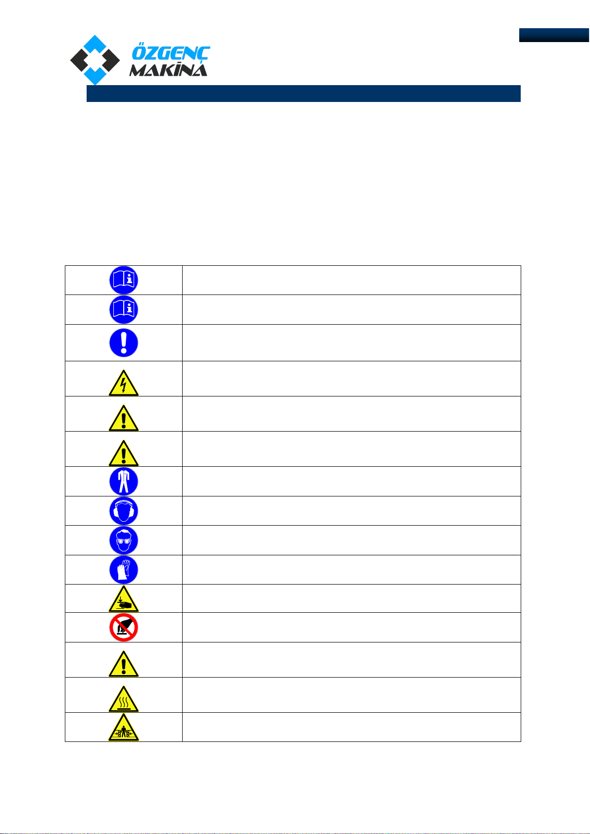
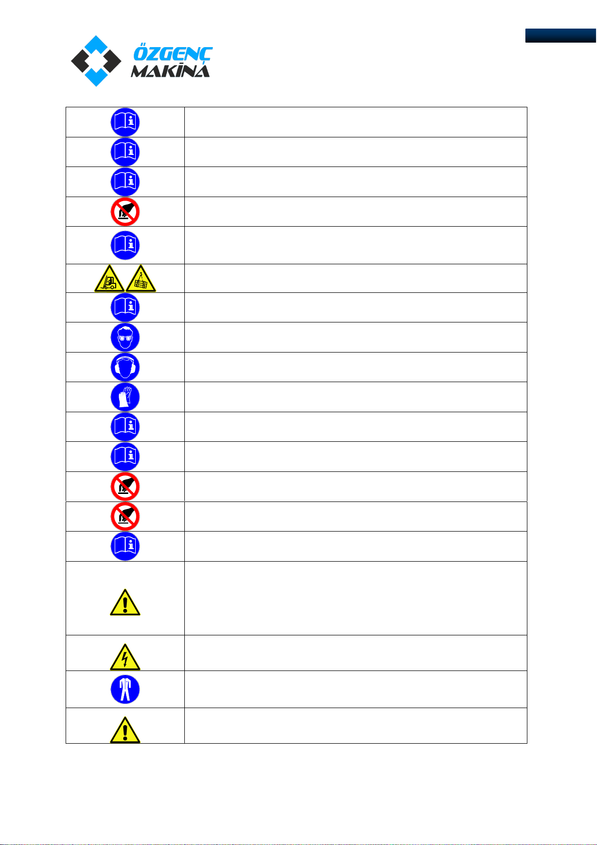
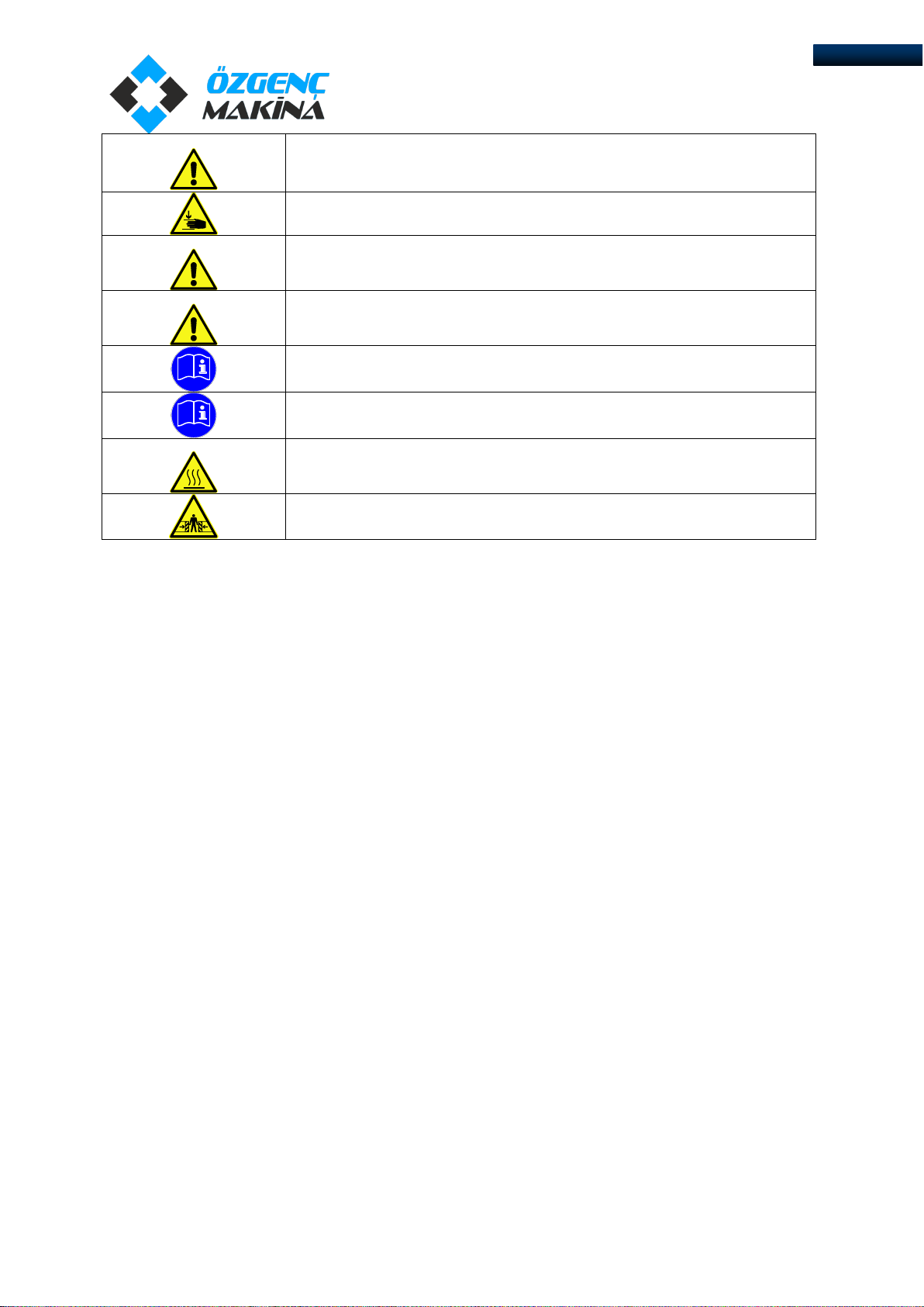
2.1 DESCRIPTION OF THE SYMBOLS USED IN THE INSTRUCTION ................................................. 4
2.2 SAFETY INSTRUCTIONS............................................................................................................ 5
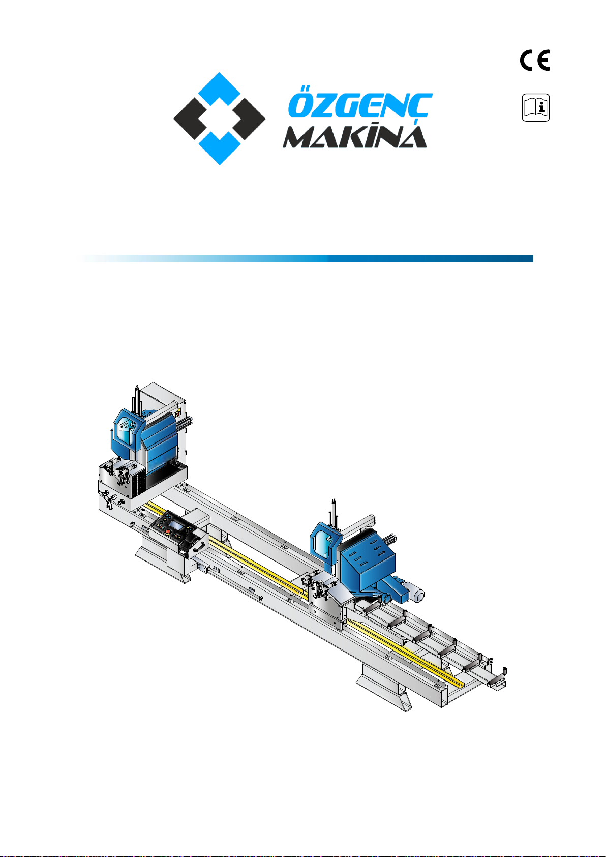
3. PRODUCT DESCRIPTION .................................................................................................................. 7
3.1 GENERAL VIEW ........................................................................................................................ 7
3.2 TECHNICAL DESCRIPTION........................................................................................................ 8
3.3 TECHNICAL FEATURES ............................................................................................................. 8
4. INSTALLATION ................................................................................................................................. 9
4.1 TRANSPORTATION INSTRUCTIONS.......................................................................................... 9
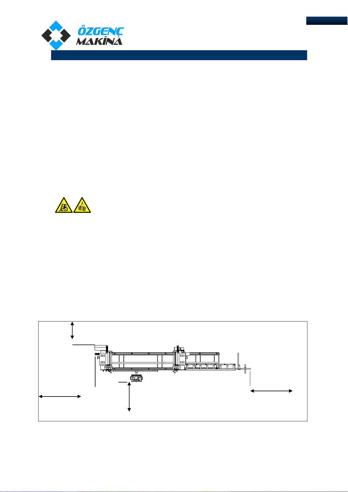
4.2 REQUIRED WORKING AREA..................................................................................................... 9
4.3 INSTALLATION SETTINGS....................................................................................................... 10
4.4 FIRST CONNECTION............................................................................................................... 11
5. PRINCIPLES OF WORK.................................................................................................................... 12
5.1 MAIN SETTINGS ..................................................................................................................... 12
5.1.1 DEGREE CALIBRATION 45° - 90° .................................................................................... 12
5.1.2 MEASURE CALIBRATION................................................................................................ 12
5.2 MACHINE CONTROL ELEMENTS ............................................................................................ 13
5.3 PLC......................................................................................................................................... 14
5.4 OPERATION OF THE MACHINE .............................................................................................. 16
5.5 MANUAL MODE..................................................................................................................... 17
5.6 AUTOMATIC MODE ............................................................................................................... 19
5.7 LONG PROFILE CUTTING over 4000 mm ............................................................................... 21
5.8 PIECES CUTTING .................................................................................................................... 22
5.9 ETH. IP (ETHERNET IP) .........................................................Hata! Yer işareti tanımlanmamış.
5.10 INTERMEDIATE DEGREE SETTING.......................................................................................... 23
6. MAINTENANCE AND THE LUBRICATION OF THE MACHINE .......................................................... 24
6.1 MAINTENANCE TABLE ........................................................................................................... 24
6.2 MAGNETIC SENSOR ............................................................................................................... 25
6.3 CHANGING THE BLADE.......................................................................................................... 25
7. PNEUMATIC ELEMENTS................................................................................................................. 26
7.1 VALVE AND CYLINDER CONTROL........................................................................................... 26
7.2 CYLINDER SPEED ADJUSTMENT............................................................................................. 27
7.3 HYDRAULIC SPEED CONTROL CYLINDER................................................................................ 28

page. 2/ 42
2
INTRODUCTION
7.4 COOLING SYSTEM.................................................................................................................. 29
7.5 FILTER-REGULATOR ............................................................................................................... 30
7.5.1 RECOMMENDED FILTER-REGULATOR OILS ................................................................... 31
8. TROUBLESHOOTING ...................................................................................................................... 32
8.1 ACTIONS TO BE TAKEN DURING FAILURE.............................................................................. 32
8.2 FAILURE –REASON –SOLUTION TABLE................................................................................. 32
9. CIRCUIT DIAGRAMS....................................................................................................................... 34
9.1 PNEUMATIC CIRCUIT DIAGRAM ............................................................................................ 34
9.2 ELECTRIC CIRCUIT DIAGRAM ................................................................................................. 36
10. WARRANTY TERMS & CONDITIONS .......................................................................................... 41

page. 3/ 42
3
INTRODUCTION
1. INTRODUCTION
We congratulate you on acquisition of the high-quality equipment. Undoubtedly, you have made a
correct and well-founded choice, production of our company is the highly reliable product corresponding to the
European quality standards. The equipment is simple in usage, has high consumer properties and will serve you
long.
User instruction contains the manufacturer states principles of work and machine use. Each operator,
beginning to work on the machine should familiarise attentively with the instruction and understand it.
At correct operation and observance requests of the present instruction the manufacturer guarantees
working capacity of the machine during a warranty period.
MANUFACTURED BY:
M.S.K. MOTOR KOMPRESOR MAKINA SAN. TIC. LTD. STI.
Address : Nilufer Organize Sanayi Bolgesi 113. Sk. No: 23 Nilufer
Phone No. : +90 224 411 07 45 pbx
Fax : +90 224 411 07 49
Web : www.mskmakina.com.tr
E-mail : info@mskmakina.com.tr
Probably that some functional features of the machine are not reflected in the given document.
Conformity of the information containing in the given document is checked by us. Nevertheless
some divergences are possible and complete conformity of the validity is not guaranteed.
The manufacturer reserves the right on production and instruction change.

page. 4/ 42
4
SAFETY APPLICATIONS
2. SAFETY APPLICATIONS
1. It is forbidden to use machine to any person, except the operator.
2. Start operation only at complete reliance that you have familiarized and have understood with
designations and the definitions, concerning safety.
3. It is forbidden to work and execute operations on the machine for operator who has not familiarized
with the given instruction,
4. Acquaintance and understanding of the given instruction has importance for prevention of aggrieving
to the operator, third persons, animal, to environment and the machine.
DO NOT MAINTAIN THE MACHINE WITHOUT OBSERVANCE OF THE ABOVE-STATED ITEMS AS SUCH
OPERATION OF THE MACHINE IS UNEQUIVOCALLY DANGEROUS!
2.1 DESCRIPTION OF THE SYMBOLS USED IN THE INSTRUCTION
Instructions on the data given for the purpose of acquaintance with the machine.
Instructions on necessity of familiarity with a management before machine tool
operation.
Instructions on safety conditions which are obligatory for observance by the user
for the purpose of the prevention of drawing of a possible damage to the
machine.
Warning of high voltage presence.
Warning of possible harm to health of the person and of any kinds of time
damage.
Warning of possibility of occurrence of failures with a deadly or traumatic
outcome.
Instructions for work in protective clothes.
Instructions on necessity of use of ear-phones at work on the machine.
Instructions on necessity of use of goggles at work on the machine.
Instructions on necessity of use of gloves at work on the machine tool.
Warning about possible trauma receptions at hands clamping.
Prohibiting sign. It is forbidden to touch. Dangerous.
Warning of performance of necessary measures before the beginning of service
of the equipment.
Warning of heat presence.
Attention! Danger of a clamp!

page. 5/ 42
5
SAFETY APPLICATIONS
2.2 SAFETY INSTRUCTIONS
ATTENTION! Read the instruction and familiarize with all rules and positions.
Keep the instruction in a reliable place. The instruction should be near at hand,
for consultations in an operating time on care of the equipment.
The expert performing works on installation of the machine tool, is obliged to
study the given instruction attentively.
It is forbidden to carry out repair at occurrence of failure of the machine for
operator, failure should be eliminated by the expert of service department.
The machine and its details are necessary for protecting from every possible
external influences. Carry out the regular control of filter-regulator and fill up oil
level at its insufficiency.
It is forbidden to be under the machine during loading and unloading.
It is necessary to provide machine grounding. It is forbidden to maintain the
machine tool without grounding!
At work on the machine it is necessary to use goggles.
Not to be treated to action of natural noise of the machine it is necessary to use
ear-phones.
At replacement of disks it is necessary to use gloves.
It is necessary to use only original spare parts.
Make thrifty use of the control panel, do not suppose any mechanical damages.
Equipment start is carried out by the expert of service department. It is
forbidden to suppose any other person to start.
Equipment repair should be carried out only by experts of the service centre and
only with use of the original spare details and parts.
Use the equipment for other purposes which distinct from are the provided
scope can lead to dangerous situations.
Be always attentive and watch that you do, do not start thoughtlessly work with
the machine. Machine operation is forbidden if you have got tired or be under
the influence of narcotic substances, alcohol or medicines. The minute
carelessness at equipment operation can lead to serious traumas or mutilations.
Operation of the machine with the damaged network cable is forbidden.
It is necessary to immediately replace the damaged cable with the new.
Use special working clothes. Don’t wear spacious subjects of clothes or an
ornament. Preserve hair, clothes and gloves from mobile knots and details. Free
clothes, ornaments or long hair can be tightened by moving parts of machine.
Before the repair or service beginning it is necessary to disconnect a supply of
electricity and compressed air from the machine.

page. 6/ 42
6
SAFETY APPLICATIONS
It is forbidden to remove the protective details which are on the machine. It is
necessary to remember that protective details of the equipment are established
for the purpose of safety at work on the machine.
Avoid clamping hands between the cylinders intended for fixing of a cross-
section and moving parts of the equipment.
Do not open safety covers to a machine blackout.
Only one operator should work on the machine.
The machine should pass regular service and adjustment. Do not use the
machine tool in faulty condition.
Do not use the machine tool in wet and damp premises.
It is forbidden to touch a heating plate of the working machine.
Attention! Do not stay between moving cutting heads.

page. 7/ 42
7
PRODUCT DESCRIPTION
3. PRODUCT DESCRIPTION
3.1 GENERAL VIEW
Picture 3.1-1 General view
1. Power switch
2. Electrical panel
3. Left stable head. Head №1.
4. Left head protective cover
5. Pneumatic clamp for left head
6. Control panel
7. Right mobile head. Head №2.
8. Right head protective cover
9. Pneumatic clamp for right head
10. Conveyor
11. Exhaust pipe
2
1
4
5
6
7
8
9
11
10
3

page. 8/ 42
8
PRODUCT DESCRIPTION
3.2 TECHNICAL DESCRIPTION
-Cutting length size and angle degree are entered from LCD-display on control panel
-Automatic head position for 45° and 90 °degrees, easy adjustment for intermediate angles
-Possibility of manual length size adjustment
-Magnetic rule length control system
-Multilanguage support
-Repetitive cut program, angle cut –variable and fixed length –fixed angle
-Extra length cut program (over 5 mt.)
-Horizontal pneumatic clamping kit
-Industrial dust exhaust
-Bearing conveyor for the movable head
3.3 TECHNICAL FEATURES
Voltage : 380 V
Frequency : 50/60 Hz
Total power : 5 kW
Air pressure : 6–8 Bar
Air consumption : 30 lt./min.
Minimum cutting length : 500 mm
Maximum cutting length : 5000 mm
Minimum cutting width : 180 mm
Maximum cutting height at 90° : 170 mm
Maximum cutting height at 45° : 120 mm
Width : 1500 mm
Length : 6500 mm
Height : 1700 mm
Weight : 1350 kg

page. 9/ 42
9
INSTALLATION
4. INSTALLATION
►The equipment has passed working tests of all mechanic, electric and pneumatic units at factory.
All materials and the spare parts have passed the complete careful control before delivery in a
transport company.
►At equipment acceptance make the control on availability/absence of any transport damages.
4.1 TRANSPORTATION INSTRUCTIONS
►The machine should be standing upright and positioned centrally on top of a wooden pallet.
While the machine is situated on the pallet, position the forklift arms under the pallet between
the runners, keeping in mind that the machine is head heavy. Move the entire unit to an
accessible area as close as possible to the final location.
►Carefully remove the packing frame surrounding the saw unit. Once completed, proceed by
elevating the machine away from the pallet base using a sling harness wrapped around the
cutting head of the saw. Ensure that the floor is as level as possible before finally positioning the
machine to the desired location.
It is forbidden to be under the machine during loading and unloading.
1. At loading to forklift it is necessary to avoid damage of cables, cylinders, hoses, filter-
regulator and control panels.
2. Means for moving should have dimensions corresponding for the machine.
3. Avoid blows of the machine tool in the course of moving.
4. Machine moving should be performed by a forklift.
4.2 REQUIRED WORKING AREA
►For high-efficiency work of the machine it is recommended to place the machine in workshop
with maintenance of indicators of the distances indicated by the manufacturer. A –B the placings
shown on the plan, it is necessary to keep plots the free. The minimum recommended distance
from the uppermost point of the machine tool to a ceiling constitutes 2 mt.
Picture 4.2-1 Required Working Area
500
mm
А
2000
mm
B

page. 10 / 42
10
INSTALLATION
4.3 INSTALLATION SETTINGS
►Care should be taken for the floor to be straight and sound the
machine will be positioned. Note that there will be sufficient distance
around the machine in order to work safely, for easy servicing and
maneuvers.
►The machine should be scaled. The machine that is well scaled will
reduce the vibration, working will be easier and the production and the
quality will also increase.
►Pressure of air should constitute 6-8 Bar. Usage of a thick hose
interferes with air pressure decrease on all length of a line. Besides, it is
necessary to avoid hit of moisture for the prevention of breakage of
valves and pneumocylinders.
►Warning: if there is no air dryer in the pneumatic system connection
of machine, parts of the pneumatic group are not subject to warranty
service!
►The electrical connections of the machine should be done by the
service staff or qualified electrician.
►The used electric switchboard should correspond to norms of safety
and electric standards. The voltage stabilizer should be connected to a
line of a supply of electricity.
►The grounding contour prevents aggrieving to the user by wandering
currents, for this reason the correct system and reliability of a contour of
grounding has special importance.
►Grounding line should be connected to the machine body.
►Voltage changes, its increase and decrease is harmful and dangerous
to the equipment. To prevent these events use a voltage stabilizer.
Otherwise the manufacturer does not bear any responsibility for possible
malfunctions.
►Warning: if there is no voltage stabilizer in electric system connection
of the machine, parts of electric and pneumatic are not subject to
warranty service!
►In the machine used a cable with 4 pins (3 phases + 1 neutral),
corresponding to IP 44 standards and the power of machine. It is
necessary to ensure that similar standards for plug sockets.

page. 11 / 42
11
INSTALLATION
4.4 FIRST CONNECTION
1. Remove the package.
2. Locate machine on an even horizotal place.
3. Connect electricity (380 V).
4. Checks the sequence of phases (3 phases + 1 neutral).
5. Connect air pressure (6-8 bar).
6. Check oil level in filter-regulator.
►The first connection should be made by service team. The manufacturer does not bear
responsibility for damages incurred by connection the machine by not service team.
First connection by service team:
Eliminate failures occured during transportation.
Check the uniformity of machine installation.
Check the electrical and air connections.
Switch on the machine
Instruct the operator of the machine
Give instruction on the safety and maintenance of machine
Note: If in new connection machine does not work, then the cause could be the inconsistency
of phases in the electrical network, so that motors does not rotate in the opposite direction, the
machine is protected by a special control-phase relay. Changes of phases in the connection socket
should be performed by service or qualified electrician.
►When phase sequence incorrect or the inclusion of a phase sequence error message displays
on the screen. To return to the main menu, first you must disconnect the emergency stop or
reverse phases and then push the "Reset".

page. 12 / 42
12
PRINCIPLES OF WORK
5. PRINCIPLES OF WORK
5.1 MAIN SETTINGS
►All necessary factory options are performed on the equipment. At wear of mechanical units or
details, at change of profile system it is necessary to change some options. Necessary options are
given below.
5.1.1 DEGREE CALIBRATION 45° - 90°
►The angle degree is automatically given by the operator via the control panel with time,
depending on the operation of the equipment may stray from the original settings. To set the
initial configuration needed to adjust the screws on the inside of the plate head.
Picture 5.1-1 Degree calibration
5.1.2 MEASURE CALIBRATION
The machine has an automatic calibration function so no calibration is needed.Each time the
machine opens it will calibrate itself.
4
5°
9
0°

page. 13 / 42
13
PRINCIPLES OF WORK
5.2 MACHINE CONTROL ELEMENTS
CONTROL PANEL
Picture 5.2-1 Control Panel
1. Button “Clamp”
2. Button “Pull out”
3. Switch “ Work 1 / 2 head”
4. Button “Start”cutting
5. Button “Start” Head № 2 motor
6. Button “Stop”Head № 2 motor
7. Emergency Stop
8. Button “Stop”Head № 1 motor
9. Button “Start”Head № 1 motor
10. Button “Start”cutting
11. Switch “Fixation”
12. Fast move buton. Use together with buton No. 13 or 14
13. Button “Backward”
14. Button “Forward”
15. Display
14
3
2
1
6
5
4
9
8
7
13
12
11
10
15

page. 14 / 42
14
PRINCIPLES OF WORK
5.3 PLC
Picture 5.3-1 PLC MITSUBISHI General view
A programmable logic controller (PLC) or programmable controller is a digital computer used
for automation of electromechanical processes.
At machine power ON, on PLC IN (Input)section following light-emitting diodes should be
ON: 5, 7, 11, 15, 16. If any of these light-emitting diodes are not ON, the machine will not
function.
PLC SIGNALS DEFINITIONS
INPUT (Input signals)
-Input X0 ON when phase A has signal
-Input X1 ON when phase B has signal
-Input X2 ON when phase C has signal
-Input X4 ON when cutting “Start” button pushed
-Input X5 OFF when Head № 1 motor’s “Stop” button pushed
-Input X6 ON when Head № 1 motor’s “Start” button pushed
-Input X7 OFF when Head № 2 motor’s “Stop” button pushed
-Input X10 ON when Head № 2 motor’s “Start” button pushed
-Input X11 OFF when “Pull out” button pushed
-Input X12 ON when “Clamp” button is pushed
-Input X13 ON when head selection 1 / 2 head occurs
-Input X14 OFF when head fixation occurs
-Input X15 OFF when “Emegency stop”button ON
-Input X16 ON when Head № 1 cylinder’s sensor has signal

page. 15 / 42
15
PRINCIPLES OF WORK
-Input X17 ON when thermal relay has overload
-Input X20 ON when Head № 2 cylinder’s sensor has signal
-Input X21 ON when “Forward” button pushed
-Input X22 ON when “Backward” button pushed
-Input X23 ON when “Fast” button pushed
OUTPUT (Output signals)
-Output Y0 ON when Head № 2 moves forward
-Output Y1 ON when Head № 2 moves backward
-Output Y2 ON when Head № 2 moves forward fast
-Output Y3 ON when Head № 1 motor is ON
-Output Y4 ON when Head № 2 motor is ON
-Output Y5 ON when clamp valve Works
-Output Y6 ON when Head № 1 valve works
-Output Y7 ON when cuttıng operation on Head № 1 occurs
-Output Y10 ON when cuttıng operation on Head № 2 occurs
-Output Y11 ON when Head № 1 motor lamp is ON
-Output Y12 ON when Head № 2 motor lamp is ON
-Output Y13 ON when Head № 2 clamp valve is ON
-Output Y14 ON when Head № 1 adjusted at 45°
-Output Y15 ON when Head № 1 adjusted at 90°
-Output Y16 ON when Head № 2 adjusted at 45°
-Output Y17 ON when Head № 2 adjusted at 90°
Before the operation starts it is necessary to be convinced of absence people (service staff,
etc.) near to the machine which can receive damages at movement of units of the machine;
the operator should be attentive for the purpose of protection of health of persons which
can be near to it, also it is necessary to warn surround persons about machine operation.

page. 16 / 42
16
PRINCIPLES OF WORK
5.4 OPERATION OF THE MACHINE
►At power supply feed on the machine display appears screen with a language selection. Select
language. (EN - English)
►After language has been selected main menu screen appears
MAIN MENU
AUTO. MODE
LONG SIZE CUTTING
CALIBRATION
MANUAL MODE
PIECES CUTTING
ETH. IP
►Main menu contains 6 sub-menu:
Manual mode
Automatic mode
Long size cutting mode (over 4000 mm)
Pieces cutting mode

page. 17 / 42
17
PRINCIPLES OF WORK
5.5 MANUAL MODE
MANUAL
TARGET
SIZE 1200 mm 90°90°
SIZE. mm
1500
Q-TY.
RESET START STOP CUTTING Q-ty.
0
Picture 5.5-1 Manual mode
1. Target. Size needed for cutting.
2. Size. Actual size on machine.
3. Head № 1 degree position.
4. Head № 2 degree position.
5. Start. Sets Head № 2 on the target size.
6. Stop. Cancels Start command.
7. “Back” arrow. Goes to main menu.
8. Cutting quantity.
9. Cutting quantity reset.
WORKING PRINCIPLE
►The principle of operation in the given mode consists in data entry (size, angle) through the
display and subsequent cutting.
1. Push on Target value to enter the cutting size. Size menu will appear. Enter required size and
push ENT, if you entered incorrect puch CLR to delete.
9
1
2
3
4
5
6
7
8

page. 18 / 42
18
PRINCIPLES OF WORK
MANUAL
TARGET
SIZE 1200 mm 90°90°
SIZE. mm
1500
Q-TY.
RESET START STOP CUTTING Q-ty.
0
1. Set the angle for stable and Head № 2s by pushing angle value (3) and (4). Head will
automatically set on 45°or 90°. To set intermediate degree see
2. Push “Start”. Head № 2 automatically goes to set size. Head automatically will be fixed and
fixation button will be lighted.
3. Put the profile for cutting on the plate.
4. Push “Clamp” (1). Pneumatic cylinders will clamp the profile. If clamping is incorrect push
“Pull out” (2).
5. Start the motors for right (5) and left (9) heads.
6. At the same time push and hold cutting “Start”buttons (4) and (10). Pneumatic covers go
down, cutting blades go out and profile cutting happens.
7. After cutting is finished leave the “Start” buttons (4) and (10). Cutting blades go back,
pneumatic covers go up, pneumatic cylinders pull out.
8. Push “Stop” buttons to swith off motors of stable and mobile heads (6) and (8)
►In single head cutting, just Head № 1 is working. To enable single cutting turn the (3) button to 1
head mode.
Attention! The “Fixation” switch should be in active position. In active position the
button is lit continuously green.

page. 19 / 42
19
PRINCIPLES OF WORK
5.6 AUTOMATIC MODE
AUTO. MODE
90°
Q-TY.
0002 START STOP
MONITOR
SIZE. mm
1500
FROM 0001 TO 0010
90°
Q-TY. 0002
SIZE. mm 0680
STEP 0001
Picture 5.6-1 Automatic Mode
1. From. Initial cutting step.
2. End. final cutting step.
3. Step number.
4. Step size.
5. Step cutting quantity.
6. Head № 2 angle position.
7. Head № 1 angle position.
8. “Start”. Programm start button.
9. “Stop”. Programm stop button.
10. Cutting quantity.
11. Length. Actual size on machine.
12. “Back” arrow. Goes to main menu.
WORKING PRINCIPLE
►Working principle of the given mode consists in automatic cutting of set steps.
1. Select step number (3).
1
2
3
4
5
6
7
12
11
10
8
9
Table of contents
Other OZGENC MAKINA Saw manuals