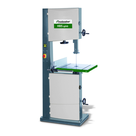
Holzstar HBS 400 User manual

HBS 400
Operating Instructions
HBS SERIES
Wood Band Saw
HBS 400
HBS 471
HBS 473

2 HBS Series | Version 1.06
Imprint
Product identification
Wood Band Saw Item number
HBS 400 5900410
HBS 471 5900471
HBS 473 5900473
Manufacturer
St rmer Maschinen GmbH
Dr.-Robert-Pfleger-Str. 26
D-96103 Hallstadt/Bamberg
Fax: 0049 (0) 951 96555 - 55
Email: [email protected]
Internet: www.holzstar.de
Information about the operating instructions
Genuine operating instructions
Published: 30.01.2019
Version: 1.06
Language: English
Author: FL
Copyright information
Copyright © 2019 St rmer Maschinen GmbH, Hallstadt,
Germany.
St rmer is the sole owner of the content of these operat-
ing instructions.
Forwarding and reproduction of this document as well as
use and notification of its content is not permitted without
explicit consent. Infringements will lead to claims for
damages.
Subject to technical modifications and error.
Content
1 Introduction ............................................ 3
1.1 Copyright ........................................................... 3
1.2 Customer service...............................................3
1.3 Disclaimer..........................................................3
2 Safety ...................................................... 3
2.1 Legend of symbols............................................. 3
2.2 Operator responsibility....................................... 4
2.3 Operating staff qualification ............................... 4
2.4 Personal protective equipment .......................... 5
2.5 Safety labels on the band saw........................... 5
2.6 Safety devices ................................................... 5
3 Intended Use........................................... 6
Technical Data........................................ 6
4.1 Table ................................................................. 6
4.2 Type plate..........................................................6
5 Transport, packaging and storage ....... 7
5.1 Delivery..............................................................7
5.2 Transport ........................................................... 7
5.3 Packaging..........................................................7
5.4 Storage .............................................................. 7
6 Description of device............................. 7
6.1 Machine ............................................................. 7
6.2 Scope of delivery ............................................... 8
6.3 Accessories ...................................................... 8
7 Setting up and connection .................... 8
7.1 Requirements for the place of operation............ 8
7.2 Set up the wood band saw ................................ 8
7.3 Electrical connection.......................................... 9
8 Settings....................................................10
8.1 Setting of the 90° table square .......................... 10
8.2 Tilting the table ..................................................10
8.3 Adjusting the saw blade guide ......................... 10
8.4 Saw blade change ............................................. 11
8.5 Adjusting the saw blade tension ........................ 11
8.6 Adjusting the running of the saw band...............12
8.7 Adjusting of the saw blade guide....................... 12
8.8 Adjusting the rip fence guide scale.................... 13
8.9 Changing the saw band speed .......................... 13
9 Operation.................................................1
9.1 Workflow ............................................................14
9.2 Rip fence............................................................ 15
9.3 Cut types............................................................ 15
10 Care, maintenance and repair..............16
10.1 Care after work ................................................ 16
10.2 Maintenance and repair................................... 16
11 Troubleshooting....................................17
12 Disposal, reusing used machines........18
12.1 Decommissioning ............................................ 18
12.2 Disposal of electrical equipment...................... 18
12.3 Disposing of lubricants..................................... 18
13 Spare parts.............................................18
13.1 Spare parts orders........................................... 18
13.2 Spare parts drawings HBS 400 ....................... 19
13.3 Spare parts drawings HBS 471 / HBS 473...... 22
1 Electrical circuit diagrams....................25
15 EU Declaration of Conformity..............26

Introduction
HBS Series | Version 1.06 4
1 Introduction
You have made an excellent choice in purchasing a
HOLZSTAR Wood Band Saw.
Carefully read the operating instructions prior to
commissioning.
They describe correct commissioning, intended use and
safe as well as efficient operation and maintenance of
your band saw.
The operating instructions form part of the wood band
saw. Keep these operating instructions at the installation
location of your band saw. Also observe the local acci-
dent prevention regulations and general safety regula-
tions for the use of the band saw.
1.1 Copyright
The contents of these operating instructions are pro-
tected by copyright. Their application is permitted within
the context of the use of the band saw. Any further use
shall not be permitted without written consent by the
manufacturer.
For the protection of our products, we shall register
trademark, patent and design rights, as this is possible in
individual cases. We strongly oppose any infringement
of our intellectual property.
1.2 Customer service
Please contact your specialist retailer if you have any
questions regarding your band saw or require any tech-
nical information. Your specialist retailer will be happy to
support you with specialist advice and information.
Germany:
St rmer Maschinen GmbH
Dr.-Robert-Pfleger-Str. 26
D-96103 Hallstadt
Germany
Repair service:
Fax: 0049 (0) 951 96555-111
Email: [email protected]
Spare parts orders:
Fax: 0049 (0) 951 96555-119
Email: [email protected]
We are always interested in valuable experience and
knowledge gained from using the application, whichthen
could be shared and be valuable to develop ourproducts
even further.
1.3 Disclaimer
All data in these operating instructions has been com-
piled on the basis of the state-of-the-art, valid standards
and guidelines as well as our many years of expertise
and experience.
The manufacturer shall not be liable for damage in the
following cases:
- Non-observance of these operating instructions
- Unintended use
- Deployment of untrained staff
- Conversions at one's own responsibility
- Technical modifications
- Use of unauthorised spare parts
The actual scope of delivery may deviate from the de-
scriptions and illustrations in this document as a result of
special variants, optional extras or recent, technical
modifications.
The obligations defined in the supply contract shall apply
in addition to the general terms and conditions and the
manufacturer's general terms and conditions as well as
the statutory regulations valid at the time of the conclu-
sion of the contract.
2 Safety
This section provides an overview of all important safety
packages for personal protection as well as safe and reli-
able operation. The sections on individual service life
phases contain additional, specifically applicable safety
information.
2.1 Legend of symbols
Safety Instructions
Safety instructions in these operating instructions have
been highlighted with symbols. Safety instructions are in-
dicated by signal terms that express the degree of risk
involved.
DANGER!
This combination of symbol and signal term indicates
a directly dangerous situation which may cause death
or serious injury if not averted.

5 HBS Series | Version 1.06
Safety
Tips and recommendations
Observe the safety information in these operating in-
structions to minimise the risk of personal injury as well
as material damage and prevent hazardous situations.
2.2 Operator responsibility
Operators are defined as the persons who operate the
machine for commercial or profit-based purposes or pro-
vide the machine to third parties for use or application
and bear the legal product responsibility in terms of the
protection of users, staff or third parties during opera-
tion.
Obligations of the operator:
If the machine is used for commercial purposes, opera-
tors are subject to the legal stipulations in terms of occu-
pational safety. For this reason, the safety instructions in
these operating instructions as well as the safety, acci-
dent prevention and environmental protection regulati-
ons valid at the installation location must be complied
with. In this process, the following shall apply in
particular:
- Operators shall obtain information about valid oc-
cupational safety regulations and determine addi-
tional hazards as part of a risk assessment which
result from the specific operating conditions at the
machine's installation location. Said risk as-
sessment shall be reflected in operating instructi-
ons for machine operation.
- During the entire machine operating time operators
must check whether the operating instructions they
created meet current standards and adapt the ope-
rating instructions where necessary.
- Operators shall clearly manage and specify the re-
sponsibilities for installation, operation, trouble-
shooting, maintenance and cleaning.
- Operators must make sure that all persons hand-
ling the machine have read and understood these
operating instructions. Operators must also regu-
larly train staff and notify of the hazards.
- Operators shall provide staff with the required pro-
tective equipment and wearing the required protec-
tive equipment shall be mandatory.
Operators shall also be responsible for maintaining the
machine in a technically perfect condition. For this rea-
son, the following shall apply:
- Operators shall make sure that the maintenance in-
tervals described in these operating instructions
are complied with.
- Operators shall regularly check that the safety
equipment is fully functional and complete
2.3 Operating staff qualification
The different tasks described in these operating instructi-
ons require different levels of skills in terms of the qualifi-
cations of operating staff working with the machine.
Exclusively persons of whom it can be expected that they
reliably complete assigned tasks shall be authorised to
carry out any tasks. Persons whose reactions have been
impaired shall not be authorized, e.g. drug users, users
under the influence of alcohol or medication.
These operating instructions specify the following perso-
nal qualifications for the different tasks:
WARNING!
This combination of symbol and signal term indicates
potentially hazardous situations which may cause
death or serious injury if not averted.
ATTENTION!
This combination of symbol and signal term indicates
a potentially hazardous situation which may cause
minor or light injuries if it is not averted.
IMPORTANT!
This combination of symbol and signal term indi-
cates a potentially dangerous situation which may
cause material damage or harm the environment if it
is not averted.
NOTE!
This combination of symbol and signal term indicates
a potentially dangerous situation which may cause
material damage or harm the environment if it is not
averted.
Tips and recommendations
This symbol highlights useful tips and recommenda-
tions as well as information for efficient and reliable
operation.
WARNING!
Risk from inadequately qualified
persons!
Inadequately qualified persons are unable to assess
the risks when handling the machine, thus putting
themselves and others at risk of severe injuries.
- All work must be carried out by qualified persons
only.
- Keep inadequately qualified persons and children
away from the work area.
Safety
HBS Series | Version 1.06 6
Operating staff:
Operating staff has undergone an induction by the ope-
rator about the entrusted tasks and potential hazards re-
sulting from improper behaviour. Tasks which go beyond
normal operation may only be carried out by the operator
if they are listed in the operation manual and the opera-
tor has made him/herself familiar with them.
Qualified electrician:
Due to the electrician's specialised training, know-how,
experience and knowledge of pertinent standards and
regulations the electrician is in a position to work on the
electrical systems, and autonomously identify and avoid
potential hazards.
Specialist staff:
As a result of specialist training, expertise, experience
and skills in terms of the relevant standards and regulati-
ons, specialist staff is able to complete the tasks they are
entrusted with and independently identify hazards and
avert risks.
Manufacturer:
Certain work must be carried out by manufacturer spe-
cialist staff only. Other staff is not permitted to carry out
this work. Contact our customer service to have the work
carried out.
2.4 Personal protective equipment
Personal protective equipment is intended to protect the
health and safety of persons at work. Staff must wear the
personal protective equipment indicated in individual
sections of these operating instructions when carrying
out the different tasks on the machine.
The personal protective equipment is described in the
following section:
2.5 Safety labels on the band saw
The following safety labels identifications are attached to
the
band saw
(Fig. 1) and must be observed
.
Fig. 1: Safety labels
1 Safety instructions: read operating instructions, wear eye pro-
tection, wear ear protection, wear respiratory protection, wear
protective clothing, wear safety shoes, no smoking | 2 warning
signs: Warning of danger of retraction on drive rollers, warning
of cuts, warning of danger points, warning of dangerous electri-
cal voltage I 3 Earthing symboln
If safety labels on the machine are damaged or missing,
this can cause errors, personal injury and material da-
mage. The safety symbols attached to the machine must
not be removed. Damaged safety symbols must be re-
placed immediately.
As soon as the signs are not clearly visible and compre-
hensible at first glance, the machine must be stopped
until new signs have been attached.
2.6 Safety devices
Safety switch
The machine is equipped with a safety switch to prevent
it from being switched on again after a voltage drop.
Speed selector
The harder the material, the lower the saw blade speed
must be.
Hearing protection
The hearing protection protects the ears against
damages of hearing due to noise.
Eye protection
Protective glasses protect the eyes against projected
parts and splashes of liquid.
Protective gloves
The protective gloves provide protection for the
hands against sharp-edged components, as well as
against friction, abrasions or deeper injuries.
Safety boots
The safety boots protect the feet against crushes, fall-
ing parts and slipping over on slippery underground.
Protective clothes
Protective work clothing means tight-fitting clothing
with low tear resistance.
Protective dust-mask
The dust protection mask protects the respiratory
tract from wood chips and wood dust.
23
1

7 HBS Series | Version 1.06
Intended Use
3 Intended Use
Die wood band saw is used for sawing angular wood or
wood-like workpieces, plastics (Plexiglas, GFK) and non-
ferrous metals (foam, rubber, leather and cork). Round
materials may only be cut with suitable holding devices.
Only saw bands suitable for the machine may be used.
It is suitable for private use, not for industrial use. Inten-
ded use also includes compliance with all information in
these instructions. Any use exceeding the intended use or
any other use is considered misuse. Different types of
saw blades can be used with the machine. The saw blade
thickness and the number of teeth/inch (tooth pitch) de-
pend on the radius to be cut. The narrower the radius to
be cut, the narrower the saw blade must be and the lower
the saw band speed must be.
For structural and technical changes to the band saw the
company St rmer Maschinen GmbH assumes no liability
Claims of any kind due to damage due to improper use are
excluded.
Misuse
The wood band saw must not be used for sawing metals.
Residual risks
If all safety regulations are observed and the machine is
used in accordance with the regulations, there are still
residual risks, which are listed below:
1. There is a risk of injury to the upper limbs (e.g. hands,
fingers).
2. Danger from falling or throwing workpieces.
3. Break/tear of the tool
4. Fire hazard due to insufficient ventilation of the motor
5. Hearing impairment during prolonged work without hea-
ring protection.
6. Contact with rotating parts or tools
7. Contact with live parts
4 Technical Data
4.1 Table
4.2 Type plate
Fig. 2: Type plate HBS 473
ATTENTION!
Certain types of wood and wood products produce
harmful dust emissions when processed. Therefore,
only use your machine in a well-ventilated room and
use an extraction system.
WARNING!
Danger in case of misuse!
Misuse of the wood band saw can lead to dangerous
situations.
- Only operate the wood band saw in the power range
specified in the Technical Data.
- Never bypass or disable the safety devices.
- Never work on materials other than those specified for
the intended use.
- Only operate the band saw in a technically perfect
condition.
- Never machine several workpieces at the same time.
Model HBS 00 HBS 71/ 73
Motor input 2000 W
230V / 50Hz
1900/2000 W
230V / 50Hz /
400V 3~/50Hz
Motor output 1500 W
230V / 50Hz
1500/1500 W
230V / 50Hz /
400V 3~/50Hz
Power input 9,0 A 8,8 A / 4,3 A
Table size 530 x 480 mm 535 x 485 mm
Table angle of in-
clination
0° to 45° 0° to 45°
Max. cutting
width without
stop
416 mm 465 mm
Max. cutting
height 90°
305 mm 285 mm
Saw band length 3378 mm 3455 mm
Flywheel Ø 426 mm 470 mm
Saw band width 6 to 25 mm 6 to 25 mm
Ø Extraction port 120 mm 120 mm
Saw band speed 460 m/min,
980 m/min
406 m/min,
818 m/min
Weight 135 kg 146 kg
Length 765 mm 800 mm
Width / Depth 520 mm 490 mm
Height 1750 mm 2000 mm

Transport, packaging and storage
HBS Series | Version 1.06 8
5 Transport, packaging and storage
5.1 Delivery
After delivery, check the band saw for visible transport
damage. If you discover any damage to the cross-cut
and mitre saw, report it immediately to the transport com-
pany or dealer.
5.2 Transport
The band saw is delivered on a pallet so that it can be
transported with a forklift or a lift truck.
Transport with a crane:
The machine can be set up with a crane in a suitable
place. The machine must be properly attached to the
crane.
The upper suspend (Fig. 3, Pos. 1) is provided for lifting
the machine. Use a crane with sufficient lifting capacity.
5.3 Packaging
All of the machine‘s packaging materials and packing
aids are suitable for recycling and must always be dispo-
sed of using material-based recycling systems.
Packaging materials made of cardboard must be shred-
ded and disposed of as part of waste paper recycling.
The foils are made of polyethylene (PE), padding is
made of polystyrene (PS). Dispose of these substances
at a recycling centre or hand them over to the relevant
waste disposal company.
5.4 Storage
Store the wood band saw thoroughly cleaned in a dry,
clean and frost-free environment. Cover the machine
with a protective plane.
6 Description of device
6.1 Machine
Illustrations in these operating instructions may de-
viate from the original.
Fig. 3: Wood Band Saw HBS 473
1 Mount
2 Saw band tension display - Display window
3 Hand wheel - Saw band tension
4 ON/OFF switch
5 Parallel stop
6 Hand wheel - Saw band speed
7 Saw blade guide
8 Height adjustment - Saw band guide
9 Display window - Saw band running
10 Tension release
11 Clamping - Saw band guide
ATTENTION!
When transporting and lifting the wood band saw,
make sure that the transport and lifting equipment
can support the load.
WARNING!
Danger of life!
If the weight of the machine and the permissible load
capacity of the lifting equipment are not observed
during transport or lifting work, the machine may tip
over or fall.
- During transport and lifting operations, observe the
weight of the machine and the permissible load
capacity of the lifting equipment.
- Check that hoists and load handling attachments
are in a wall-free condition.
NOTE!
- The machine may only be loaded and unloaded by
qualified personnel.
- Never drive directly with the forks under the
machine to lift it!
NOTE!
For transport, all covers must be attached to the
machine frame.
- The machine must not be rocked by the crane
during transport.

9 HBS Series | Version 1.06
Setting up and connection
12 Suction nozzle
13 Motor
14 Table adjustment
15 Adjusting screw - Saw band running
16 Lower door lock
17 Upper door lock
6.2 Scope of delivery
- Wood Band Saw
- Saw band16,0 x 0,5 x 3378 mm / 4 TPI (HBS 400)
- Saw band16,0 x 0,5 x 3455 mm / 4 TPI
(HBS 471/473)
- Saw table
- Handwheels
- Handwheels
- Parallel aluminium stop
- Instruction manual
6.3 Accessories
Example HBS 400:
- Saw band 6,0 x 0,65 x 3378 mm / 6 TPI
- Saw band 10,0 x 0,5 x 3378 mm / 4 TPI
- Saw band 16,0 x 0,5 x 3378 mm / 4 TPI
- Saw band 20,0 x 0,5 x 3378 mm / 4 TPI
- Saw band 25,0 x 0,5 x 3378 mm / 4 TPI
- Angle stop HBS 400
7 Setting up and connection
7.1 Requirements for the place of operation
Remove the band saw from the packaging and all pro-
tective films. Do not set up or operate the machine in a
damp or wet environment. The air humidity should not
exceed 80% and the measured room temperature
should be between 5°C and 35°C. The machine should
not be operated in a humid or wet environment.
The installation or work area must be dry and well venti-
lated.
7.2 Set up the wood band saw
The wood band saw is already delivered largely as-
sembled. Only a few parts like the saw table, the rip
fence and the handwheels have to be assembled after
delivery.
Step 1: After unpacking, park the machine at the desired
location.
Step 2: Screw the base plate of the machine to the sub-
strate via the holes using four M10 screws (Fig.
4, Pos. 1).
Tips and recommendations
We recommend to use only high quality original Holz-
star accessories. Only with original accessories a
perfect operation and optimal results can be guaran-
teed.
NOTE!
To reduce noise, a rubber layer can be placed bet-
ween the machine and the workbench. This effectively
prevents vibrations and noise.
CAUTION!
Risk of injury from an unstable machine!
Check the stability of the machine after setting it up
on stable ground.
ATTENTION!
In order to ensure sufficient stability of the machine, it
should be bolted to the ground. There are 4 holes at
the bottom of the machine housing for this purpose.
ATTENTION!
Do not overtighten the fixing screws of the base plate.
The base plate must not be distorted
Use protective gloves!
Wear protective clothes!
Wear safety boots!

Setting up and connection
HBS Series | Version 1.06 10
Fig. 4: Mounting on the subsurface
The wood band saw is already delivered largely as-
sembled. Only a few parts like the saw table, the rip
fence and the handwheels have to be assembled after
delivery.
The machine is made ready for operation with the follo-
wing steps:
Assembly of the saw table
Step 1: With the help of another person, lift the saw table
to the angle adjustment.
Step 2: Fasten the saw table to the trunnion with 4
screws (Fig. 5, Pos.1) and one washer each.
Fig. 5: Assembly of the saw tableh
Assembly of the rip fence
Step 1: First mount the rear fence rail (Fig. 6, Pos. 1) with
two M6x20 screws and the matching washers.
Step 2: Then fasten the front fence rail (Fig. 6, Pos. 2)
with the four thumb screws and the washers
(M8).
Step 3: Hook the rip fence (Fig. 6; Pos. 3) into the rear
fence rail and then into the front fence rail.
Fig. 6: Assembly of the rip fence
Assembly of the handwheels
Step 1: Mount the small handle (Fig. 7, Pos. 1) in the lo-
wer position.
Step 2: Mount the large handle (Fig. 7, Pos. 2) to the up-
per position.
Fig. 7: Assembly of the handwheels
Use a 14 mm. or 10 mm. open-end wrench to fasten it.
7.3 Electrical connection
When connecting the power supply, make sure that the
characteristics (voltage, mains frequency) are identical
to what is indicated on the type plate.
Step 1: Check that the wood band saws turned off.
Step 2: Connect the machine to the mains.
ATTENTION!
The mains plug must be disconnected before any
maintenance and conversion work is carried out on
the wood band saw.
DANGER!
Risk of fatal injury due to electric
shock!
Contact with live components may result in fatal
injury. Switched-on electrical components can make
uncontrolled movements and lead to serious injuries.
ATTENTION!
All work on the electrical installation may only be car-
ried out by a qualified electrician.

11 HBS Series | Version 1.06
Settings
8 Settings
8.1 Setting of the 90° table square
The table may be set at 90o to the saw blade by adju-
sting the table stop screw under the table. The table stop
screw rests on the top of the lower wheel bandwheel
housing (Fig. 8):
Fig. 8: 90°-Stellung des Sägetisches
Step 1: First loosen the clamping nut (Fig. 8, Pos. A).
Step 2: Adjust the screw (Fig. 8, Pos. B) as follows, that
the angle between table and band saw blade is
90°. (Check this with an angle if necessary).
Step 3: Retighten the clamping nut (Fig. 8, Pos. A), ma-
king sure that the setting is maintained.
8.2 Tilting the table
The saw table inclination can be set as follows:
Step 1: Loosen the lock handle (Fig. 9, Pos. A) on the ta-
ble trunnion.
Step 2: Turn the table tilting knob (Fig. 9, Pos. B) to ad-
just the table to the desired angle. Use the angle
indicator scale on the trunnion bracket to find the
desired angle..
Step 3: Retighten the lock handle to secure the table.
Fig. 9: Slope adjustment of the saw table
8.3 Adjusting the saw blade guide
Fig. 10: Adjusting the saw blade guideg
Step 1: Loosen the clamping screw (Fig. 10, Pos. A).
Step 2: Adjust the optimum height by turning the hand-
wheel (Fig. 10, Pos. B).
Step 3: Clamp the saw band guide using the clamping
screw (Fig. 10, Pos. A).
ATTENTION!
The machine must be switched off and the mains
plug disconnected before all adjustment, set-up and
maintenance work is carried out on the machine.
NOTE!
The upper saw band guide must be adjusted accor-
ding to the height of the workpiece. The upper band
guide unit should be set approximately 2-3 mm higher
than the thickness of the workpiece to be sawn. The
adjustment must be carried out or checked before
each sawing operation.

Settings
HBS Series | Version 1.06 12
8.4 Saw blade change
Fig. 11: Change the saw blade
Step 1: Open the front covers by turning the top and bot-
tom door locks (Fig. 11; A).
Step 2: Remove the front rip fence strip (Fig. 11; B) by
loosening the four wing screws.
Step 3: Release the saw band tension by actuating the
quick release lever (Fig. 11; C).
Step 4: Carefully remove the old band saw blade from
the rollers and guide it through the slot in the
table.
Step 5: Place the new band saw blade centrally on both
rollers.
Step 6: Tension the saw band again by turning the quick
release (Fig. 11; C). Mount the rip fence bar and
close the front covers.
Step 7: Re-adjust the saw band run, the saw band guide
and the saw band tension as described.
8.5 Adjusting the saw blade tension
Step 1: By turning the handwheel (Fig. 12, Pos. A) the
saw blade tension is increased or decreased by
means of a spring.
Step 2: The correct tension can be read off the scale
(Fig. 12, Pos. B).
Fig. 12: Saw blade tension
Use protective gloves!
NOTE!
Make sure that the teeth of the saw band face the
front edge of the table and the tips of the teeth point
downwards.
NOTE!
If the band saw is not used for a longer period of time,
the band saw blade must be released. This must be
indicated on the outside of the machine. Before you
put the machine back into operation, the saw band
must be tensioned.
DANGER!
Risk of injury!
- If the tension is too high, the saw band may tear.
- If the tension is too low, the actuated band saw roller
can rotate and the band saw blade stops.
NOTE!
To change saw bands of the same width, this basic
tension setting no more needs to be changed. The
standard quick clamping system allows the saw band
to be released without changing the basic tension set-
ting.

13 HBS Series | Version 1.06
Settings
8.6 Adjusting the running of the saw band
Fig. 13: Saw band running
Step 1: Release the clamping lever (Fig. 13, Pos. A) by
turning it counterclockwise.
Step 2: Turn the upper saw band wheel with the front
cover open. Turn the adjustment screw (Fig. 13,
Pos. B) counterclockwise or clockwise to adjust
the band saw blade run. You can observe your
settings in the side window.
Step 3: Then turn the saw band wheel several times to
check your settings.
Step 4: Close the front covers and secure your settings
with the clamping lever (Fig. 13, Pos. A).
8.7 Adjusting of the saw blade guide
The upper and lower saw blade guides are similar in con-
struction and must be adjusted as listed below.
Upper saw blade guide:
Fig. 14: Saw blade guide
Step 1: First loosen the screw and push the rollers up to
approx. 1.5 mm towards the saw blade teeth.
Step 2: Clamp the screw again.
Step 3: To adjust the lateral guide rollers (Fig. 14, Pos. D),
loosen the clamping plates (Fig. 14; C) and adjust
the guide rollers with the adjusting screw (Fig. 14,
Pos. B) so that there is a gap of approx. 0.5-0.7
mm between them and the saw band. If the gap is
set too small, the bandsaw blades will wear faster!
Step 4: Retighten the screws (Fig. 14, Pos. C).
Step 5: Loosen the screw (Fig. 14; A) and slide the rear gui-
de roller on the saw band backs.
Step 6: Retighten the screw (Fig. 14, Pos. A).
Lower saw blade guide:
Fig. 15: Saw blade guide
NOTE!
Before the saw blade run can be adjusted, a concrete
adjustment of the saw blade tension is necessary.
Disconnect the machine from the power supply as
with all adjustment work.

Settings
HBS Series | Version 1.06 14
Step 1: First loosen the screw (Fig. 15, Pos. A) and slide
the rollers up to approx. 1.5 mm to the saw blade
teeth.
Step 2: Retighten the screw (Fig. 15, Pos. A).
Step 3: Loosen the screws (Fig. 15, Pos. B) and adjust
the guide rollers so that there is a gap of approx.
0.5-0.7 mm between them and the saw band. If
the gap is set too small, the bandsaw blades will
wear out faster!
Step 4: Retighten the screws (Fig. 15, Pos. B).
Step 5: Loosen the screw (Fig. 15, Pos. C) and slide the
rear guide roller on the saw band backs.
Step 6: Retighten the screw (Fig. 15, Pos. C).
8.8 Adjusting the rip fence guide scale
Fig. 16: Adjusting the rip fence guide scale
Step 1: Push the rip fence towards the saw band and
loosen the screw (Fig. 16; A).
Step 2: Move the scale along the mark in the window. If
necessary, you can also insert the screw (Fig.
16; A) in another position to fix the scale.
Step 3: To check the settings, saw a test piece first if
necessary and readjust the scale.
8.9 Changing the saw band speed
The wood band saw has a high and a low saw band
speed. On the lower impeller (Fig. 17; A) and two belt
pulleys of different sizes are mounted on the motor.
Fig. 17: Saw band speed
Step 1: Turn the handwheel (Fig. 17, Pos. D) to release
the tension of the V-belt (Fig. 17, Pos. C).
Step 2: Place the belt on the two rear pulleys to set the
fast speed or on the two front pulleys to set the
slow speed.
Step 3: Then retighten the V-belt using the handwheel
(Fig. 17, Pos. D).
ATTENTION!
Before changing the speed always make sure the
machine has been unplugged from the electrical sup-
ply!
NOTE!
The correct belt tension is achieved as soon as the
thumb can only be pressed through approx. 1 cm.
Fast
Slow

15 HBS Series | Version 1.06
Operation
9 Operation
i
9.1 Workflow
Step 1: Check that the band saw is turned off and the po-
wer plug is unplugged.
Step 2: Check that all covers and safety devices are pro-
perly installed.
Step 3: Check the workpiece for foreign objects such as
nails or screws and remove them if necessary.
Step 4: Select and clamp the saw blade, check the moving
parts for easy movement.
Step 5: Adjust the inclination angle if necessary.
Step 6: Connect the extraction unit to the extraction soc-
ket and switch it on.
Step 7: Switch on the saw by pressing the green START
button.
Step 8: Guide the workpiece against the saw blade.
Step 9: After finishing the sawing work, switch off the
wood band saw with the red STOP button,
switch off the extraction after approx. 20 seconds
and pull the mains plug.
DANGER!
Risk of fatal injury due to electric
shock!
Contact with live components may result in fatal
injury. Switched-on electrical components can make
uncontrolled movements and lead to serious injuries.
- Disconnect the mains plug before making any adju-
stments to the machine.
WARNING!
Risk of injury!
There is a risk of injury to the operator and other per-
sons if they do not comply with the following rules.
- The Wood Band Saw may only be operated by an
instructed person.
- The operator must not work when under the influ-
ence of alcohol, drugs or medication.
- The operator must not work if he is overtired or suf-
fers from illnesses affecting his concentration.
ATTENTION!
Risk of crushing!
In case of unintended work on the device, there is a
risk of injury to the upper limbs.
ATTENTION!
- Health-damaging emissions of wood dust when
used indoors.
- Risk of kickback of the workpiece.
- Risk of ejection of branch parts and workpiece parts.
ATTENTION!
- Protect the machine from humidity (danger of short
circuit!).
- Do not overload the machine! You will work better
and safer in the specified performance range.
- Never use blunt or damaged saw blades. Check that
the appropriate saw blade is used.
Use hearing protection!
Use protective goggles!
Wear protective dust-mask!
Wear safety boots!
Wear protective clothes

Operation
HBS Series | Version 1.06 16
9.2 Rip fence
For straight longitudinal cuts, the workpiece is guided
along the rip fence. The rip fence can be adjusted to the
desired cutting width.
9.3 Cut types
Longitudinal cuts
The longitudinal cuts are sawing along the workpiece
grain. It is possible to saw along a torn line without a rip
fence or along the rip fence for a better result.
For right-angled cuts (the table is at right angles to the
band saw blade), the rip fence is placed to the left of the
band saw blade so that the workpiece can be guided
safely along the fence with the right hand.
In the case of longitudinal mitre cuts with an inclined ta-
ble, the rip fence must be fitted to the right of the blade
on the downward side (if the width of the workpiece per-
mits this) in order to secure the workpiece against slip-
ping.
Cross sections
Cross-section is the sawing at right angles to the grain of
the wood. This type of cut can also be carried out without
a rip fence.
Freehand cuts
The ease with which curved cuts can be made is one of
the outstanding features of a band saw. For curved cuts,
choose a band saw blade with a width that can cut the
smallest radii in your workpiece. For freehand cutting,
you should work at a low feed rate so that the saw band
can follow the desired line. Make sure that you do not
push the workpiece sideways out of the cutting line. This
will cause the saw band to run and jam in the cutting
groove.
NOTES FOR SAWING!
- The band saw does not cut the workpiece automati-
cally. The user allows cutting by guiding the work-
piece into the moving saw blade.
- The teeth cut the workpiece in the direction of the
worktable (down).
- The workpiece must be moved slowly into the saw
blade.
- Every person who works with the band saw needs
instruction.
- When cutting thicker workpieces, make sure that the
band saw blade is not bent or twisted. This increa-
ses the service life of the saw blade.
- For all cutting operations, the upper band guide
must be positioned as close as possible to the work-
piece. This ensures the best possible operator
safety.
- Always guide the workpiece with both hands and
hold it flat on the band saw table to avoid jamming
the band saw blade.
- Always use the rip fence or the mitre fence for all
cutting operations for which they can be used. This
prevents the saw blade from running out of the cut-
ting line, especially when working with an inclined
table.
- Plan the necessary steps in advance. An old crafts-
man's rule is "measure twice, saw once". It is better
to make a cut in one operation rather than in several
sections that may require retraction after the band
saw blade has come to a standstill.
- Remember that the band saw blade causes a kerf
and adjust the kerf width so that the kerf is in the
section part of the workpiece. Add a little extra if the
workpiece edge is to be machined later.
Tips and recommendations
It can often be useful to remove excess material
about 10 mm from the cutting line. In the case of very
tight radii, which the saw blade can no longer cut pro-
perly, cuts at right angles to the curve line and at a
small distance from each other can help. When
sawing the radius, the material falls off so that the
saw band cannot jam.

17 HBS Series | Version 1.06
Care, maintenance and repair
10 Care, maintenance and repair
10.1 Care after work
Step 1: Disconnect the mains plug from the socket.
Step 2: Empty and clean the suction device.
Step 3: Clean the machine of chips and sawdust with
compressed air (Attention: wear protective gog-
gles and dust mask!) and/or with a brush or dry
cloth.
Step 4: Clean the wood band saw regularly with a damp
cloth and a mild detergent.
Step 5: Spray or oil all unpainted metal surfaces with a
little anti-rust spray.
Step 6: Regularly lubricate the bearings and guide points
with a high-quality machine grease.
10.2 Maintenance and repair
Maintenance and repair work may only be carried out by
qualified personnel.
If the band saw does not function properly, contact your
dealer or our customer service. The contact details can
be found in chapter 1.2 Customer Service.
Check the machine for external damage before use.
The V-belt must be checked for correct tension after the
first 20 hours of operation. After every 250 operating
hours (every six months), check the V-belt for wear, po-
rosity and tension.
All protective and safety devices must be reinstalled im-
mediately after completion of repair and maintenance
work.
Extraction system
Check the extraction system daily for sufficient function.
If the extraction system does not function or functions
only to a limited extent, it must be repaired. Only then
may the wood band saw be put into operation
DANGER!
Risk of fatal injury due to electric
shock!
Contact with live components may result in fatal
injury. Switched-on electrical components can make
uncontrolled movements and lead to serious injuries.
- Before starting cleaning and maintenance work,
switch off the machine and disconnect the mains
plug.
- Connections and repairs to the electrical equipment
may only be carried out by a qualified electrician.
Use protective gloves!
NOTE!
Never use strong cleaning agents or solvents for any
cleaning work. This can damage or destroy the de-
vice.
ATTENTION!
Do not remove the chips with your bare hand. There is
a risk of cutting injuries due to chips and tools!

Troubleshooting
HBS Series | Version 1.06 18
11 Troubleshooting
ATTENTION!
If one of the following errors occurs, stop working
with the machine immediately. Serious injury could
result.
All repairs and replacement work may only be carried
out by qualified and trained personnel.
Problem Possible cause Solution
The wood band saw does not
start when the switch is actua-
ted.
1. No power supply.
2. Defective switch.
1. Plug in the plug or have the power
connection checked by qualified person-
nel.
2. Have the switch replaced by qualified
personnel.
The motor is running, but the
saw band is not.
1. The quick release lever is open.
2. The band saw blade runs off the
wheels.
3. The saw band is broken.
4. The V-belt is damaged.
1. Switch off the motor and clamp the quick re-
lease lever.
2. Switch off the motor and adjust the saw band
correctly.
3. Insert a new saw band.
4. Insert a new V-belt.
The saw band does not cut a
straight line.
1. The rip fence is not used.
2. The feed too fast.
3. The saw band teeth are blunt or
damaged.
4. The saw band guides are not adju-
sted correctly.
1. Use the rip fence.
2. Press the saw band with the workpiece.
3. Insert a new saw band.
4. Readjust the saw band guide.
The saw band does not cut or
cuts only very slowly.
1. The saw band teeth are blunt due
to the sawing of wrong material.
2. The saw band was installed the
wrong way round.
1.Insert the correct saw band for the mate-
rial to be processed.
2. Insert the saw band correctly.
Chips and sawdust accumu-
late in the machine.
1. It is a normal situation. 1. Clean the machine regularly. If neces-
sary, use a vacuum cleaner.
Sawdust in the motor housing. 1. Abnormal amounts of sawdust. 1. Clean the motor housing with a vacuum
cleaner.
2. Use a suction unit
The machine is not sawing at
the correct angle.
1. The saw table is not correctly adju-
sted.
2. The saw band is blunt or too much
cutting pressure has been applied.
1 Adjust the saw table correctly.
2. Change the saw blade and exert less
pressure.
The saw blade run cannot be
adjusted correctly.
1. The wheels are not adjusted. De-
fective bearings.
2. The saw blade run has not been
adjusted correctly.
3. Low-quality saw band.
1. Contact your dealer.
2. Adjust the saw blade run.
3. Use a different saw blade.

19 HBS Series | Version 1.06
Disposal, reusing used machines
12 Disposal, reusing used machines
In your own interest and to protect the environment make
sure that all machine components are exclusively dis-
posed of in as intended and permitted.
12.1 Decommissioning
Disused machines must be decommissioned immedi-
ately to prevent misuse at a later point and putting the
environment or persons at risk.
Step 1: Remove all environmentally hazardous process-
ing materials from the used machine.
Step 2: If necessary, disassemble the machine into as-
semblies and components that are easy to han-
dle and suitable for recycling.
Step 3: The machine components and processing mate-
rials must be disposed of using the intended dis-
posal methods.
12.2 Disposal of electrical equipment
Note that electrical equipment contains a variety of recy-
cling-capable materials and also environmentally haz-
ardous components.
Please help to separate these components and dispose
of them responsibly. In case of doubt, contact your local
waste disposal authority. Consult a specialist disposal
agent for recycling if needed.
12.3 Disposing of lubricants
Lubricant manufacturers provide disposal information for
the lubricants used. If necessary, request product-spe-
cific data sheets.
13 Spare parts
13.1 Spare parts orders
Spare parts are available from authorised retailers or di-
rectly from the manufacturer. The contact details have
been listed in section 1.2 Customer service.
The following key data is required for queries or spare
parts orders:
- Device type
- Item number
- Position number
- Year of construction
- Quantity
- Desired shipping type (post, freight, sea, air, ex-
press)
- Shipping address
Spare parts orders without the aforementioned data can-
not be taken into account. The supplier shall determine
the shipping type if no relevant data was provided.
Data on the machine type, item number and year of
manufacture is listed on the type plate attached to the
device.
Example
The saw blade guide pulley for the wood band saw HBS
400 must be ordered. The saw blade guide pulley is
identified in the spare parts drawing 1 with the number
96.
- Type of device: Wood Band Saw HBS 00
- Item number: 5900 10
- Spare parts drawing: 1
- Position number: 96
The order number is: 0-5900 10-1-96
The order number consists of the item number, the dra-
wing number, the position number and one digit in front
of the item number (0).
- Place the digit 0 in front of the item No.
- Also place the digit 0 in front of the position No. 1
trough 9.
The item number of your device:
Wood Band Saw HBS 400 5900 10
Wood Band Saw HBS 471 5900 71
Wood Band Saw HBS 473 5900 73
DANGER!
Risk of injury caused by the use of
incorrect spare parts!
The use of incorrect or faulty spare parts may cause
risks for operating staff and damage as well as mal-
functions.
- Exclusively genuine spare parts made by the manu-
facturer or spare parts authorised by the manufac-
turer shall be used.
- Always contact the manufacturer if you are unsure.
NOTE!
The manufacturer warranty shall be rendered void in
the event of a use of unauthorised spare parts

Spare parts
HBS Series | Version 1.06 20
13.2 Spare parts drawings HBS 400
The following spare parts drawings are intended to help identify the necessary spare parts. To order, please send a copy
of the list of spare parts with the marked components to your dealer.
Spare parts drawing 1 - HBS 00
Fig. 18: Spare parts drawing 1 - Wood Band Saw HBS 400

21 HBS Series | Version 1.06
Spare parts
Spare parts drawing 2 - HBS 00
Fig. 19: Spare parts drawing 2 - Wood Band Saw HBS 400
This manual suits for next models
5
Table of contents
Other Holzstar Saw manuals

Holzstar
Holzstar TKS Series User manual

Holzstar
Holzstar TKS 254 E User manual

Holzstar
Holzstar KGZ 305 E User manual

Holzstar
Holzstar KGZ210 E User manual

Holzstar
Holzstar HBS Series User manual

Holzstar
Holzstar FKS 315-2000 E User manual

Holzstar
Holzstar HBS 231-1 User manual

Holzstar
Holzstar TKS 250 SC User manual

Holzstar
Holzstar TKS 316 E User manual

Holzstar
Holzstar ADH 2540 230V User manual